Alright, I tried to type up my overall process for you guys. Sorry for the text bomb, this stuff can be hard to describe though text!
All these instructions are using Aspire, but I know they can be translated to CC.
Note that when it comes to a good crisp inlay, precision is absolutely essential — especially for inlays with small/fine details. Upgrading the the HDZ has made this a much smoother process for me, due to the increased stability and precision. And always use your machine to level your stock, even if it’s just a standard .015” surfacing pass. That way you have a starting depth you know you can 100% rely on.
Male piece
This is the most complex, piece but once you do it a couple times it gets pretty routine. Here is my process:
-
Use your machine to surface your inlay piece to a total height of .25” (Here’s what I like to do: zero your machine to the top of your stock, and set your zero points. Then use the paper method to zero your machine to the wasteboard. Do not set your zero point again — just look at Carbide Motion and record the difference in the z-depth between the top of your stock and the wasteboard. Convert to inches, subtract .25”, and there’s your total cut depth. For example, if your stock turns out to be .678” thick, your cut depth will be .428”)
-
In Aspire (or CC), copy/paste the inlay design you are using for the Female piece below, and then flip it horizontally (this is very important, or else your pieces will not line up!)
-
Add an outer border around the inlay design. I like to use the offset tool and create an offset border of .25”. (See screenshot)
-
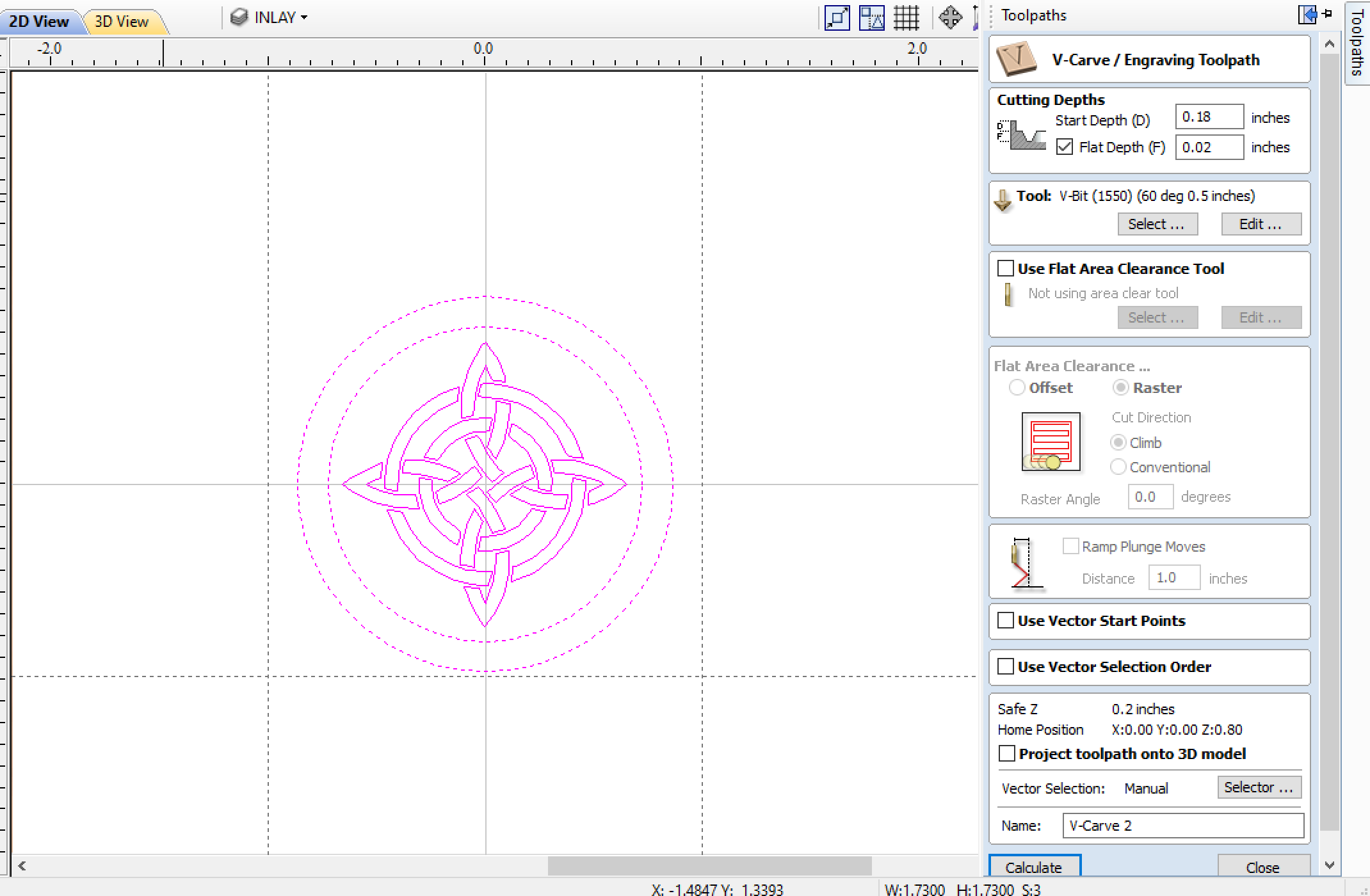
Select the reversed inlay design and the new border you just created, and then create a new vcarve toolpath.
-
Use the following settings:
- Tool — the same tool you used to carve the female piece (very important to use the same exact tool, both in design and on your actual machine!)
- Start depth = the total cut depth from the surfacing job above, plus .18” (using the example above, that would be .428 + .18, or .608”)
- Cut depth = .02”
- Larger area clearance tool = 1/8” end mill (The general idea here is that your starting depth will be .18” below the surface line of your stock, with a cut depth of .02, which will give you a total cut depth of .2”)
- When you create a path with an area clearance tool, chances are the software is going to want to run the clearance path first. Don’t do that for your male piece, especially if you have fine details or sharp corners. I have had much more success running the vcarve path first, then the clearance path, and then re-running the vcarve path again to take care of any deflection issues. This tends to result in less chipping in the male inlay piece, which is important if you are using expensive stock!
- Again, run this path slowly. I use the same 35 imp/ 20k rpm combo as the female inlay above, though I would love to hear what settings others use for vcarving fine details.
- Finally, cut out your inlay pieces. Hopefully you are using the blue tape and glue method to keep your pieces secure. I take my vacuum off, and then run a profile tool path on the offset line I created in step 3 above, using a 1/8” end mill. I always run it with a final pass of .02”, so that last pass is nice and gentle and doesn’t chip my inlay or send it flying across the table.
Female piece
This part is the most straightforward. And I usually like to do this after making my male inlays, because I prefer to keep the main piece secured to the table during glue up and when removing the backing. Plus I typically have more work to do on the piece once the inlays are finished, so I like to get all my male pieces done first if I can.
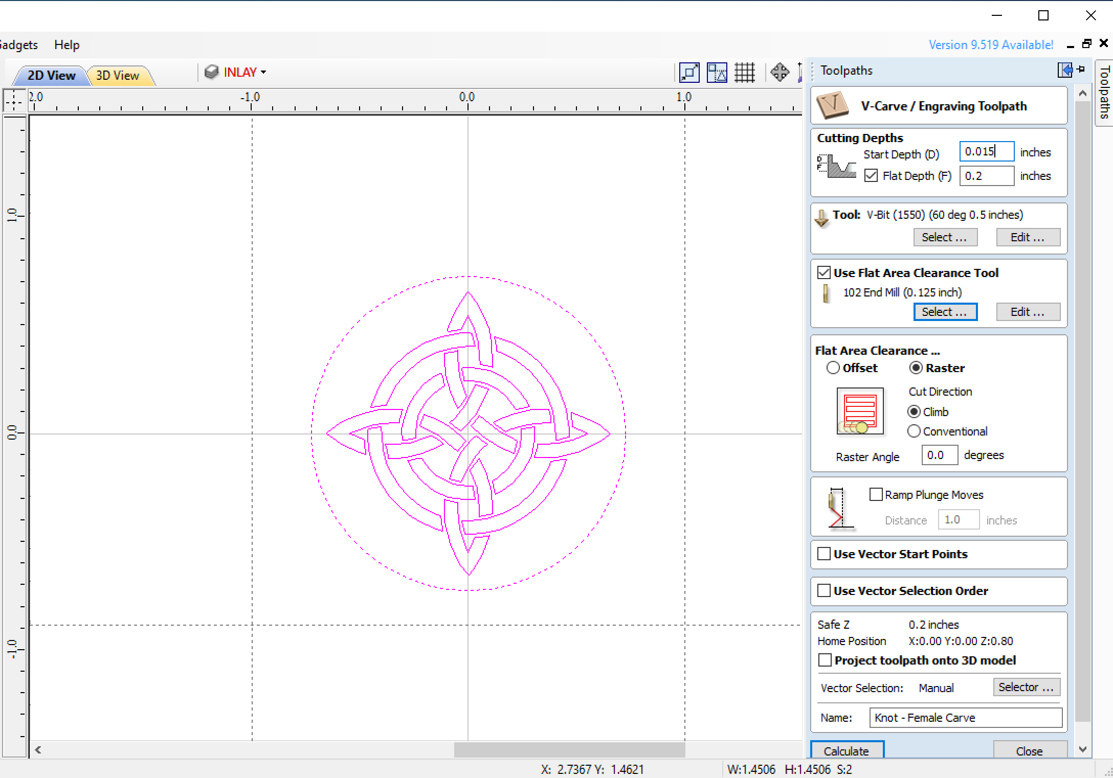
- Just do a standard vcarve with a good sharp 60 degree vbit, and set a flat depth of .2”. I like to use a somewhat shallow .1” DOC to minimize tool deflection.
-
I like to use a 1/8” end mill for the flat area clearance tool. For the female piece, I like to do the clearance pass first (but not for the male piece, as I will explain later.)
-
I generally like to run the vcarve path a second time, just to account for any tool deflection. This seems to be especially helpful for corners and edges — as the vbit moves from a deep cut to a shallow cut, the forces change so the deflection change, which sometimes makes the corners a bit rounded. Doing a second pass usually takes care of this.
-
When it comes to feeds and speeds, I find that a slow/high combo is the way to go for precision and detail. I slow the feedrate to about 35 ipm, and set my spindle to 18,000 or 20,000 rpm. (I’d love to hear from others about their own vcarve feeds/speeds, it seems to take a lot of trial and error to get right, and changes depending on how fine your details are.)
INLAY MATING
Here’s where it gets kinky.
- First, make sure both pieces are nice and clean. Use a hobby knife to eliminate any fuzz or imperfections. Avoid the temptation to use sandpaper — you can easily over-sand and your inlays won’t line up quite right.
- Before gluing, confirm that your inlay pieces match by gently placing the male piece into the female piece, and gently push down while twisting back and forth. You should feel your pieces “lock” into place, and the backing material should be a uniform distance from the female stock (with just a .02” gap, if you did your math right!)
- After confirming your inlays match up, do your glue up. If using wood glue, be sure to brush the glue on all surfaces — especially the edges. Remember that you will have only .02” glue gap underneath your inlay, so don’t complete overdo it, but make sure you are thorough. No dry spots. Because I do all my inlays on the CNC bed, I have to find clever ways to clamp the inlay securely. Sometimes I just put a surfacing bit into my spindle, put a second piece of flat scrap wood onto the inlay, and then manually move the spindle down to secure the inlay in place. This gets tricky if I am gluing multiple inlays simultaneously

- If you are impatient like I am, I have also found you can use CA glue. Cover the male piece in CA glue, and if you are brave, sprinkle some baking soda into female piece, and then mate your pieces. You will have a fraction of a second to make sure your inlay is lined up. I you skip the baking soda it will have a few more seconds to jiggle it into place.
BACKING REMOVAL
This has been a fairly touchy process for me, since I prefer to use my machine to remove the inlay backing. I can’t tell you how many beautiful inlays I have ruined because I didn’t have this process down. So here’s what I do, after several rounds of trial/error.
-
First, a brief note about why we used some of the settings above, much of which was done to make this step as easy as possible. First, we made sure that our male inlay piece was surfaced down to .25”. This was to ensure that the backing material was as thin as possible, while remaining sturdy enough for the carve and glue up. Now that the male is glued into the female, we only have .07” of backing material to remove, which reduces the forces involved and lowers the chances of ruining our nice new inlay that we just spend god knows how many hours making and waiting to dry. Also, when we cut out the male inlay pieces, by running the 1/8” profile on the .25” offset line (not “inside” or “outside” the line, but “on” the line), we can minimize the amount of backing material “overhang” on the inlay piece, which also becomes important when removing the backing. We want as little extraneous backing material as possible here. All that said, because we took these precautions, removing the backing is pretty straightforward. However, I take a VERY conservative approach here, so it can be a bit time consuming, depending on the size of your inlay.
-
For the removal tool path, simply run a pocketing tool path with the cut depth set to the surface of your piece. And use a 1/8” end mill. I’ve had a much harder time with a .25”, the forces are just too strong. I also sometimes set my cut depth to be just a tiny fraction deeper than my stock surface, about .005” lower or so, so that the inlay material has something to “push against” as it is being cut and therefore reduces chipping in sharp corners. But be careful if you have fine details, you can start to lose them quick if you cut too far beneath the surface. That said, I generally run a backing removal path with a 1/8” bit that is set to the surface depth, and then I run a new .005” surfacing pass across the entire piece with a .25” bit in order to remove any tool marks.
-
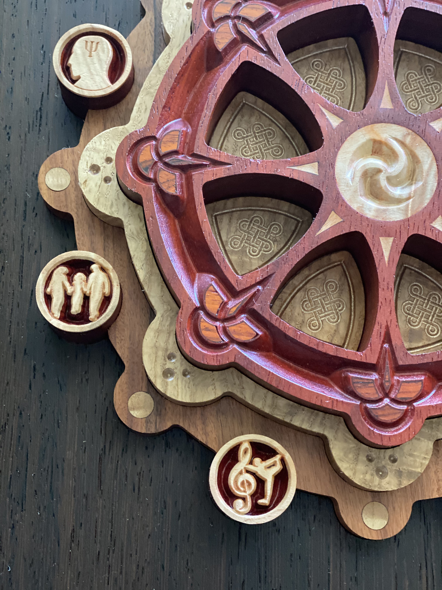
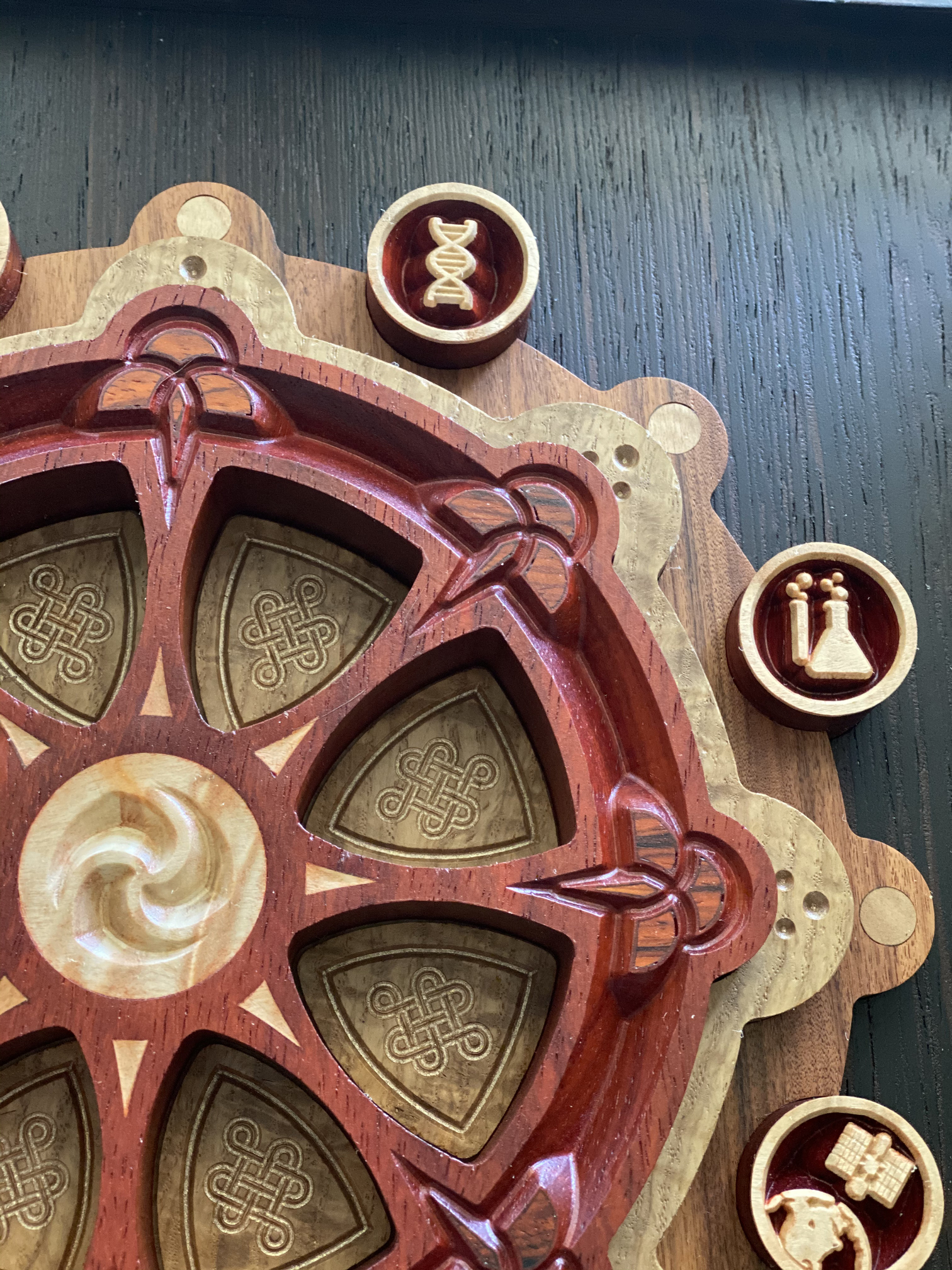
Pay attention to the direction of your pocket raster, especially if your inlay has sharp corners. Some of my pieces have thinly tapered diamonds (see the piece below), and I really have to be careful with the raster direction or else the sharp tips can easily chip. I have found that rastering in the same direction as your sharp angles really helps (so, if I have a diamond with a really sharp tip that’s facing up or down, I will do a y-axis raster so the machine is moving in the same direction as the sharp edge.
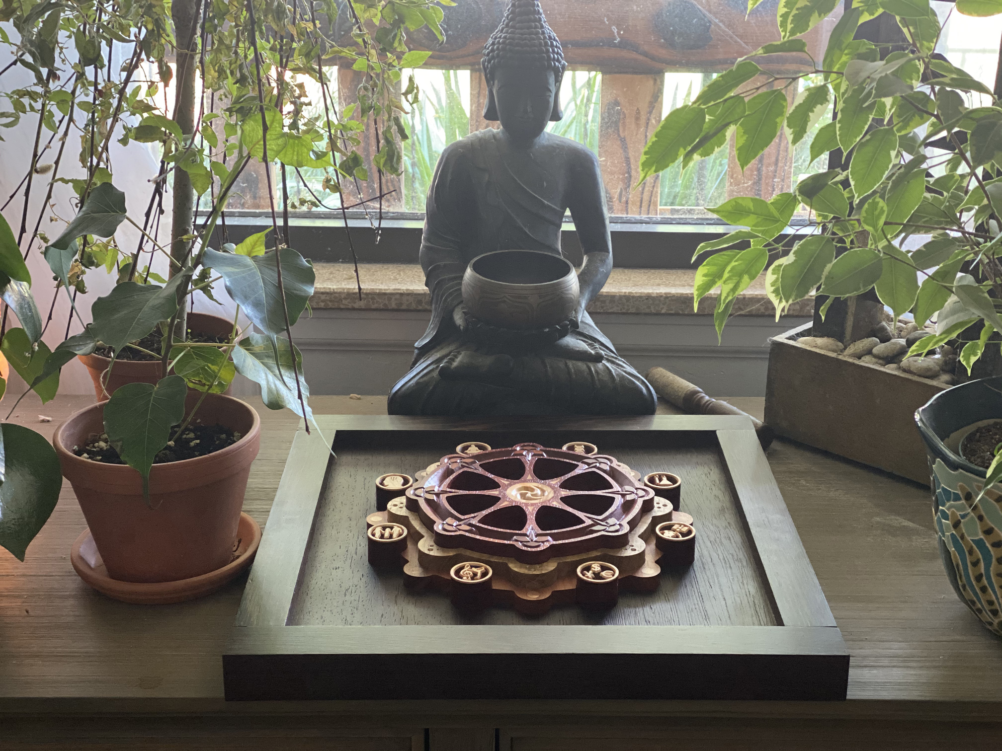
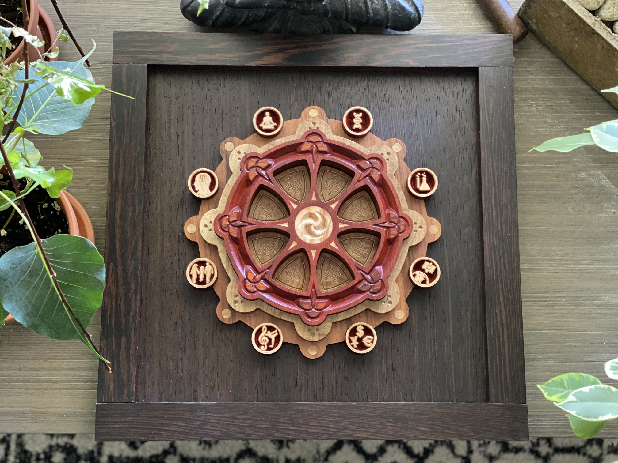
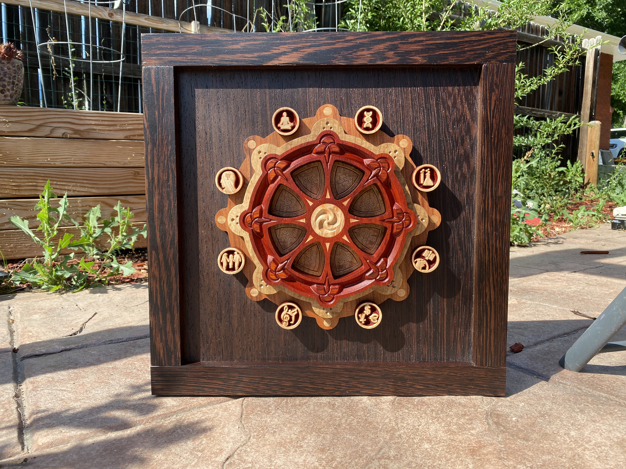
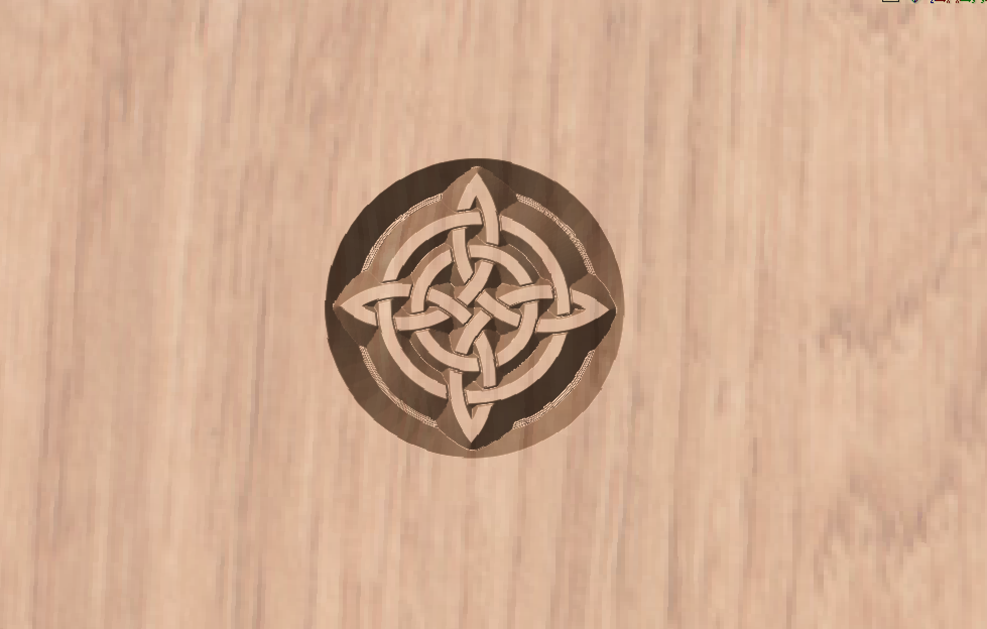
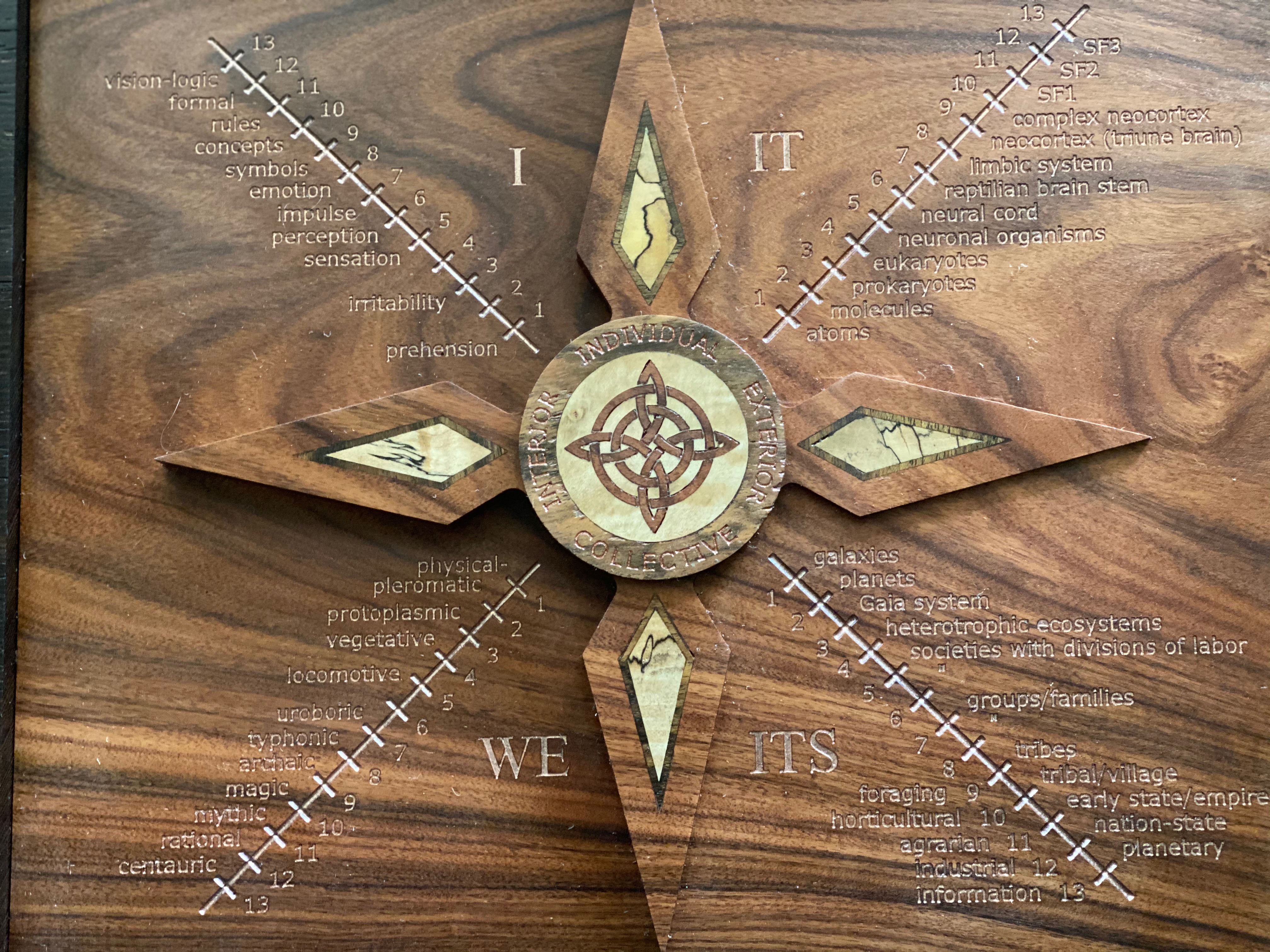
Knot inlay final result:
Here you can see the final result for the knot inlay above, as well as some examples of “double inlays”. Notice how sharp those diamonds are – that’s why I have to be super careful about raster direction when removing the inlay backing!
Holy crap, that was hard to write out! If I missed anything, or wasn’t clear enough with any of these instructions, let me know and I will try to clarify. And understand that this is just my own process, taking what I’ve learned from others and adding my own experimentation. I’d love to know if anyone approaches these differently, or has anything to add!