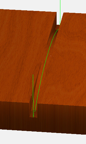
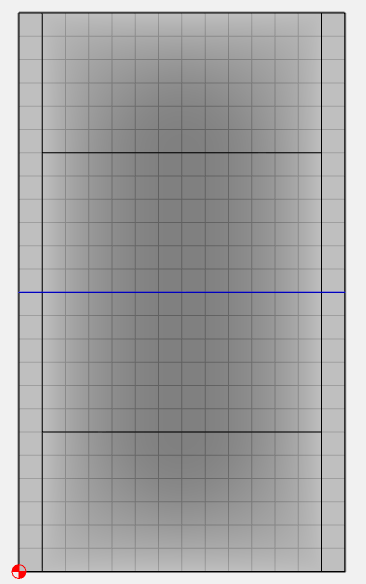
I am working on making my first fretboard of my own (previously bought already slotted fretboards). I created the .stl file of the fretboard without slots…no problem there. I even created the radiused fret slots by projecting the slot lines onto an a curved surface. The problem I am having is that I believe when I save the slots as an svg file and import them into carbide create to do the toolpaths, I believe it compresses it down to 2d and I lose the 16" radius of the fret slots. I want a uniform depth for the slot in the finished radiused board, so I need the slot to follow the radius of the fretboard when it is cutting. I do NOT want a flat bottomed fret slot. How can I do this??
SVG files are 2D and not 3D. Maybe a guitar maker, there are plenty here, can chime in about how they do their arched frets.
There is no direct way to do this in CC (that I know of). Although a “Curve Drive 3D” path where you select a curve & cut Left/Right/On the curve & follow a 3D contour would be pretty cool.
I suspect other fretboard makers are either using a different software to program the slots, or just cutting them flat bottomed.
You could cut them flat bottomed at the highest point and then use a fret saw to finish them up. At least this way the machine is marking the location & starting the slot.
OK, this might work. Model the bottom of the fret slot as an offset from the top surface of the fretboard.
For each fret draw a rectangle representing the centerline of the fret slot. I tried 0.002 wide.
Then program a 3D finish path cutting the same direction as the fret slot. I had to play around with the stepover to get a single pass, and it’s not exactly on the centerline of the slot. But since my slot is only 0.002 wide, it’s not going to be more than 0.001 off.
I also modeled some runoff around the edge to give the tool a lead-in/lead-out without falling to the table.

fret_slot.c2d (3.7 MB)
What program did you use to do this step?
I used Fusion 360 for the whole design. It took me quite a while to figure out how to project the lines onto a curved surface because I kept doing it incorrectly initially. It’s not actually difficult, I was just doing it wrong.
Lots of Fusion users here for future issues.
Why not generate toolpaths from Fusion?
The trace operation in Fusion would work, as it uses sketch lines and not features. It is kinda wonky to setup the toolpath depths.
I did something similar to this initially. I created a full fretboard (STL file) with the fret slots already “cut in” on the design. I think the problem I had was that my stepover was not small enough so it was not cutting in some of the fret slots when I looked at it in the simulation. Since the end mill I have is 0.023, do I have to use that end mill to do the 3D finish for the whole fretboard? because that could take a while. Or, can I do a 3D finish with, say my .025" ball mill, then do another 3D finish with the 0.023 to just just the fret slots? Also, I think if I spent the time learning how to do toolpaths in Fusion 360, I would probably already be done with this. Ha!
Or, if you’re lazy like me you can use this F360 add-in by Brad Anderson. Not just for the fret board and neck but the entire guitar.
That’s likely what I will have to do. I just need to figure out how to do the toolpaths in fusion now.
Thanks for sharing this. If I had not already designed it in fusion, this would be very helpful. I’m sure it will come in very helpful for something else guitar related in the near future.
This topic was automatically closed 30 days after the last reply. New replies are no longer allowed.
