OK guys, I’m failing to grasp something about CNC and I’m hoping someone can help me understand.
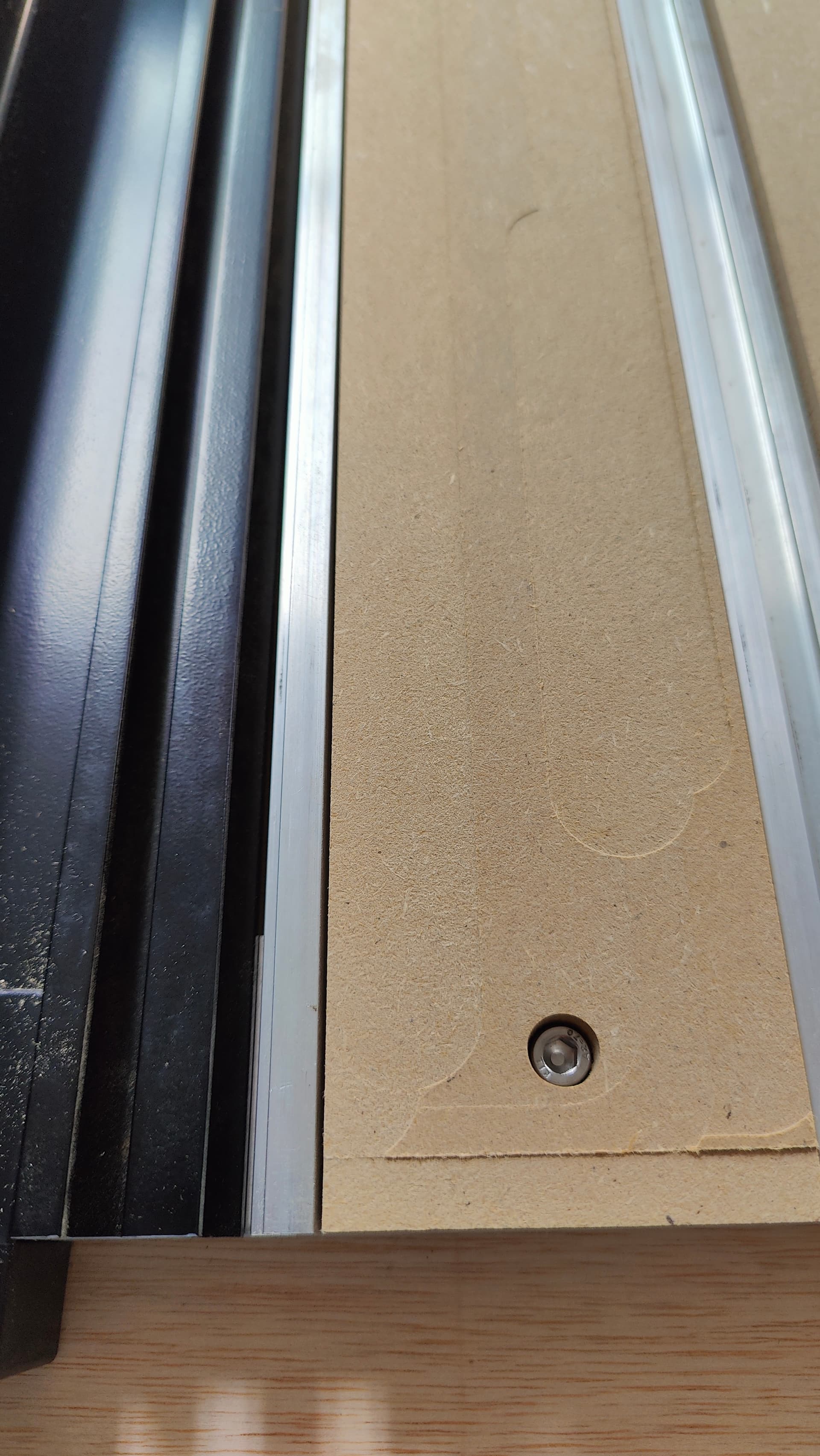
I’m trying to surface my hybrid bed on my Shapeoko. I got lucky and came up with a program that got most of a slat (left a half inch strip on the front edge), so I did one slat at a time. Now I want do the full bed. The issue I’m having is the start point and keeping the machine from trying to travel outside it’s limits (I tried multiple times.
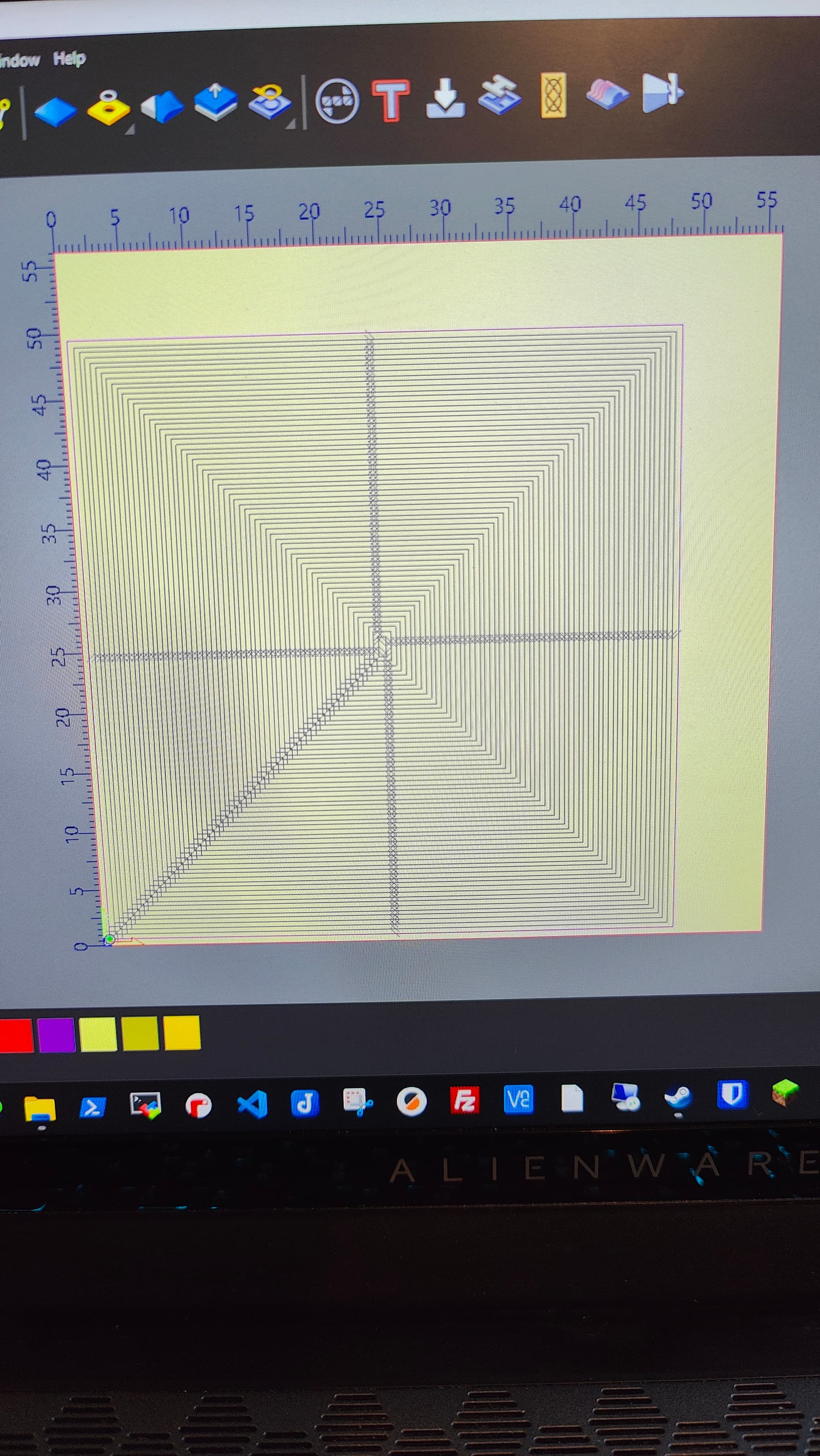
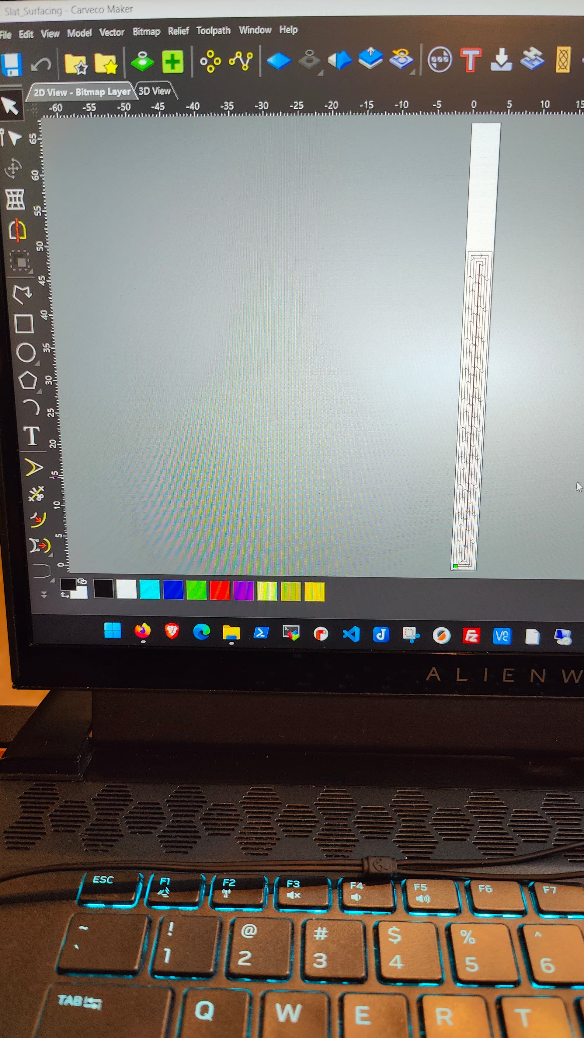
I set X Y zero on the bottom left off the edge of the first slat, Y0. Yet no matter what I do with the vector or cutting area I end up with starting part way up and in the middle of the first slat. Then I moved the vector to the bottom left corner and got it to get the edges, but every time it reaches the end of X or Y the machine grinds and tries to go past it’s limits. I’ve included pics, please help.
Will your machine reach the whole bed? I think the SO5 is the only machine that will. ??
If so, then you should be able to set your zero at the lower left corner of the spoilboard, measure your spoilboard & program to that size.
It’s a good idea to know the physical limits of your machine. Initialize the machine. After initialization, the head will be sitting near machine 0,0,0, but each axis will back off just a bit. I think 5mm (0.197"),
So, -0.197, -0.197, -0.197. If you click the word “POSITION” on the readout, it will change to MACHINE POSITION. Move X & Y all the way to the front left corner until they stop. Whatever the MACHINE POSITION reads, without the minus signs, that is your “Envelope” or limits. Write these numbers down. (I wrote them right on the front of my enclosure with a sharpie.)
That is the maximum size your program can be. And if your program is that size, and your zero is lower left, the only place it can be is at the front-left limits. If you move your zero anywhere else, you will hit the limits at the back & right.
I figured out something that works, but I still don’t fully understand it all. I would think things were more precise than this, but I had to fiddle with the design numerous times before I got it correct. The sides of the model (X) could be right on the edges of the work area, but the Y had to overhang on both ends to to get them. Maybe I’m just not comprehending the geometry or something. Non the less the job is running and has done really well. I did an Offset Raster from the outside in, I’m slightly concerned about what it will do in the center.
The thing that saved me is running simulations, I totally forgot that I could set Z zero a few inches above and let it run without touching anything. Duh.
I was told by some people to do one slat at a time, and several more people said do the whole bed at the same time. One of those people was SkyOne who always give great answers to my questions.
Thanks everyone for trying to answer my questions.
That’s one level bed! Now I can start practicing on other stuff. I’ve spent two weeks getting surfacing the bed down. I’m going to put some MDF down on top, surface it, then start practicing through cuts, which is most of what I plan on doing.