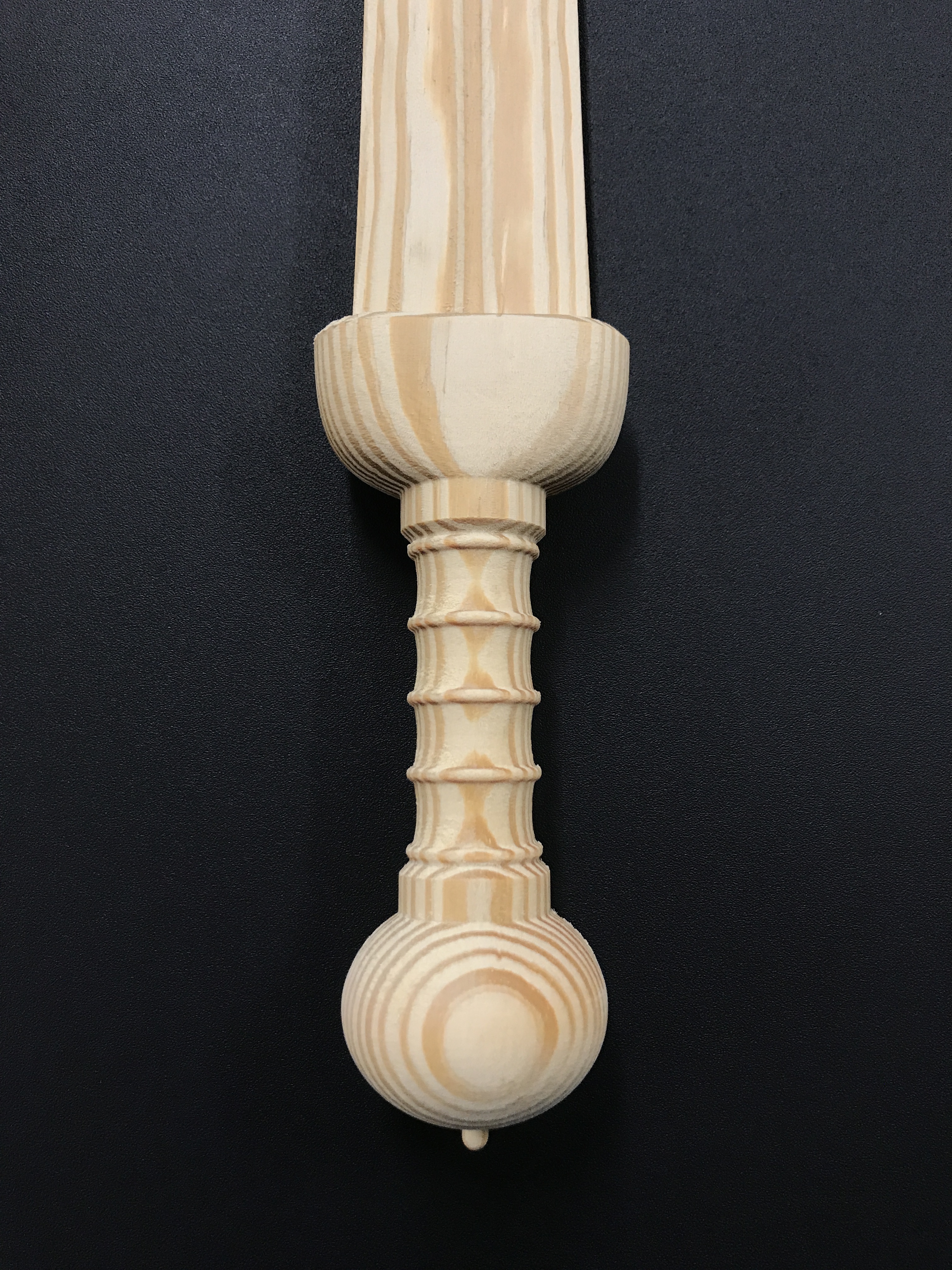
A friend asked me to help him with a project where he wanted to make a sword that looked like a Roman Gladius. I thought it was a cool idea and ran with it. I eventually created my own 3D model in Fusion360 because I didn’t care for the lower polygon count of the ones I found on Thingiverse. This is just the first one, done as a test before we try different hardwood combinations. I’m really impressed with how well it came out. These pictures are before sanding and oil. I did a 2-sided 3D toolpath in VCarve Pro and I couldn’t feel a seam between the halves at all. Now I want to do a couple different pop culture swords and hang them in my shop as decorations. (Thundercats, Voltron, etc.)
Roughing Tool Path:
1/4" EM
100"/min
1/8" DOC
40% stepover
Once I had the model designed the way I wanted in F360:
-Go to Make>3D print.
-Select the model
-Ignore “Preview Mesh”
-Select High for “Refinement”
-Deselect “Send To A 3D Print Utility”.
It will then save it as a new .STL 3D model to wherever you choose to save it.
In VCarve Pro:
-Set up a 2-sided job, zeroing off the Material Surface (be sure to check “Zero Off Same Side” meaning you’ll set Z zero from the bed after you flip).
-Hit Ok
-Go to Modeling tab>Import a component or 3D model> select your .STL file
-Orient it within your work piece, Scale it (if need be) and Center Model in the work piece.
-Set Zero Plane Position in Model to the center
-Set the Overcut Distance to a little past half the depth of your work piece. This is so it will cut just past the center and not leave a seam. Most choose the radius of their ball nose, I chose the full diameter of mine just to be safe.
-hit OK
-Go to Clipart>Clipart>3D tabs and add your tabs. I chose 6 half-inch tabs but probably would have been fine with 4.
-Go to Drawing and add 3 asymmetrical holes the size of your dowels. (snug fit) I did two at the bottom, one at the top. This is how you’ll align the X any Y of the work piece when it’s flipped.
-Select all Tabs and Dowel holes>right click>Copy to other side.
That’s all for the initial setup, then you’ll go to the Toolpaths:
-For the Top side, in Material Setup, you’ll make sure to set Z zero at the top of the work piece, Center the model position in the material.
-hit OK
-My first tool path was a Profile toolpath for the dowel holes using the 1/4" EM. These will go in to the work piece. (1" deep)
-Second Tool path was a 3D Roughing Toolpath with the same 1/4" EM. (Machining Limit Boundary: Model, Boundary Offset: 0.25, Machining allowance: 0.04, Roughing strategy: Z level, raster Y, Ramp 0.5")
-Third Toolpath was 3D finishing with the 1/16" BN. (Machining Limit Boundary: Model, Boundary Offset: 0.0625, Area Machine Strategy: Raster)
-Hit Toggle Top/ Bottom Side
-In Material Setup, Z zero is now the machine bed.
-Set up the same three Toolpaths but this time the dowel holes are a separate toolpath file and go into the SPOILBOARD!
-3d Roughing and Finishing should be the exact same unless your model is Asymmetrical. Remember, Z zero is now set to the machine bed. (I keep saying that because I buggered it up)
A couple notes on what I learned:
-On the XXl, Z travel is about 3 to 3.25 inches. My workpiece was 2.625 inches thick, so I had to slide the router way up in the bracket and leave enough of the tool sticking out to go 1.375" deep.
-It also had to go all the way down to the bed and cut 0.5" deep. Any deeper and the Z carriage would have slid off the rails. I also had to take the springs off because their tension would have caused the Z axis belt to skip teeth on that far of a travel.
-No clamps were big enough to hold this so I screwed it directly into the bed away from my dowel holes. Double sided tape won’t work because unless you account for its thickness.
-Each side took about 4 hours with tool changes.
Thank you for such a detailed rundown - it all makes good sense. I’ve not done any double sided machining yet, and use F360 and Aspire V9 so will definitely give this a shot
If you’re making more swords, you should take photos and screens through the whole thing and post a tutorial up in that section, if you’re into that sort of thing!
Thanks again, it came out beautifully , got any pics after finishing?
Glad it was helpful. I don’t have Aspire but from what they were saying in the tutorial, Aspire works very similarly to VCarve for this.
Unfortunately, I don’t have any pics of it finished. My friend came to pick it up just as I was about to put oil on it. He says I’ll get it back so I’ll post pictures then. If and when I do another one, I’ll gladly post a tutorial. I’ve learned tons of information from this community and others and like trying to do the same for others.
Yeah as far as I can see Aspire is just the same as VCarve Pro with a few extra modelling features. It’s great software
I have learned a lot on here too, and think that as the forum gets more experienced we should all try and share our awesome projects so other people can do the same, especially in CNC as most of it isn’t obvious when you’re learning, and one little thing (like zeroing off the same side!) can ruin a job and frustrate people!
My brother would love a sword like that, I think I will try it with a piece of 2x4 to start with
edit with your finishing toolpath, did you run it parallel to the grain? I assume the finish would be better and also it’d be faster due to less change in direction…
This is actually from a Southern YelIow Pine 2x12 from Lowes. I use those for all sorts of things around the shop, especially test cuts!
I ran the finishing toolpath perpendicular to the grain. I’ll admit I didn’t think about the benefits of running it parallel but will try it the next time. I was more concerned with getting the handle nice and round and getting into those nooks and crannies. However, I learned a trick in the Vcarve forum from a guy who does great 3D carving. He runs the toolpath in one direction, and if there are a lot of fuzzies after, he’ll leave it in place, put on a coat of shellac to stiffen them, then run the toolpath in the other direction. The final product requires very little sanding. (according to him)
@JFischer911 Any reason you didn’t just set up the CAM in Fusion 360?
I’m probably in the minority, but I don’t find V-carve to be very intuitive. I do want to spend more time with it, though.
Only because I’m much more familiar with Vcarve. I’ve been using it for a few years and am realy comfortable with it.I’ve only been playing with F360 for about a year and haven’t even delved into the CAM side of it yet, though I definitely will.
The only suggestion I have for you, if you’re going to do more of these, is to use REST machining during the finishing pass. There a Vectric tutorial on it, but basically it boils down to using a 1/4" ball nose for the finishing pass, previewing it to see what the bit was too big to do, then do a finishing pass of only those spots with the 1/16 ball nose. Cut your machining time to probably a quarter of what the 1/16 bit does by itself?
That is a good sugestion! I gave that a go some time ago, really good for big detailed relief carvings, it turns a 15hr carve into a 2hr carve
Cool idea about the shellac and second pass too, I’ll have to give that a shot.
Though F360 is very powerful, I find V-carve much faster and easier to get an efficient toolpath without any errors. Plus it is great for nesting parts efficiently. Both programs have their uses, and between them you can do pretty well any job
I appreciate you posting this. I just bought a guitar neck file online and I have the STL, DXF and DWG files and need to be able to create my two-sided toolpaths, so this was great timing. I’ll be watching that tutorial and seeing if I can apply it to my project.


 , got any pics after finishing?