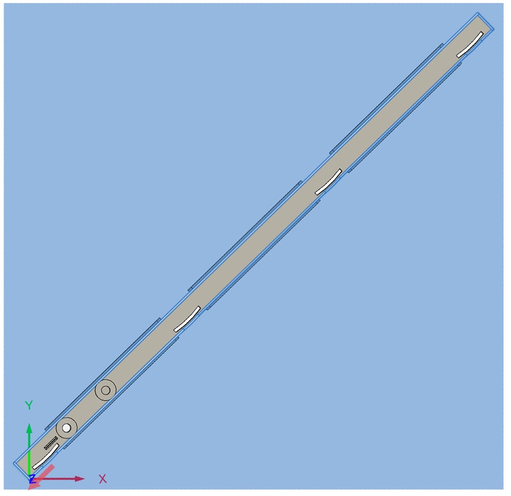
This has me stumped: I’ve designed a dozen or so projects in Fusion and the finished dimensions always come out exact. I’m now designing a tablesaw miter bar, and all my widths are too wide (length and thickness are OK). But, before you say something’s wrong with my x-axis stepper or whatever, here’s the layout:
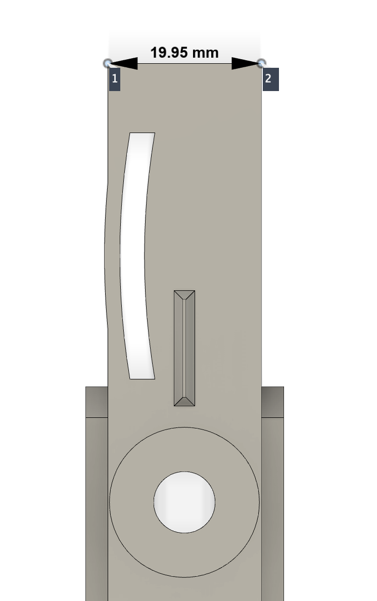
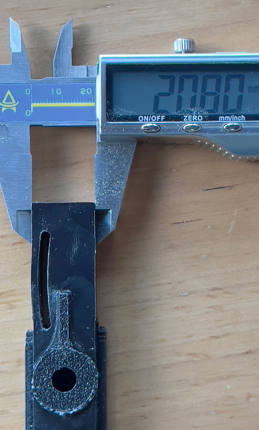
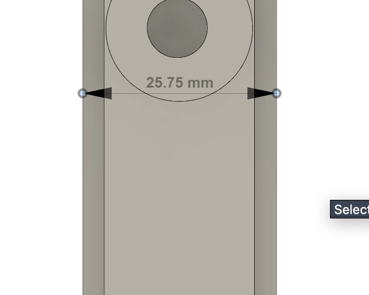
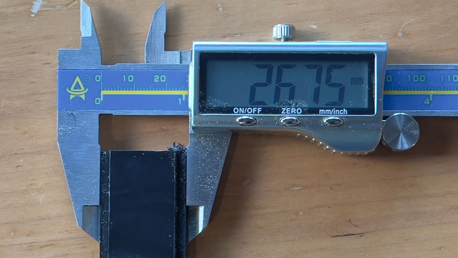
So, at a 45º angle this is not something mechanical in the Pro, it’s something I did in Fusion. I even re-milled an older project and it came out fine. What I did, however, was change some of my Fusion parameters to flip the expansion slots to the other side of the bar. Here’s some photos of measurements from a piece I milled and the corresponding Inspect measurements in Fusion:
I’ve looked and re-looked at my toolpaths, but while my roughing passes have some “Stock to Leave,” my final ones don’t.
If anyone has the inclination, here’s my Fusion file - I’m at wit’s end at this point and may need to start all over if I can’t figure out what’s wrong. MiterBar SpringsOnRight.f3d.zip (476.2 KB)
OK, after another of doing my best Curly Stooge impression (aka hair-pulling), I decided to trash my tool paths and rebuild from scratch. And for some reason that works:
Ugh, I spoke too soon. This probably needs to be filed under HowTo->Machining.
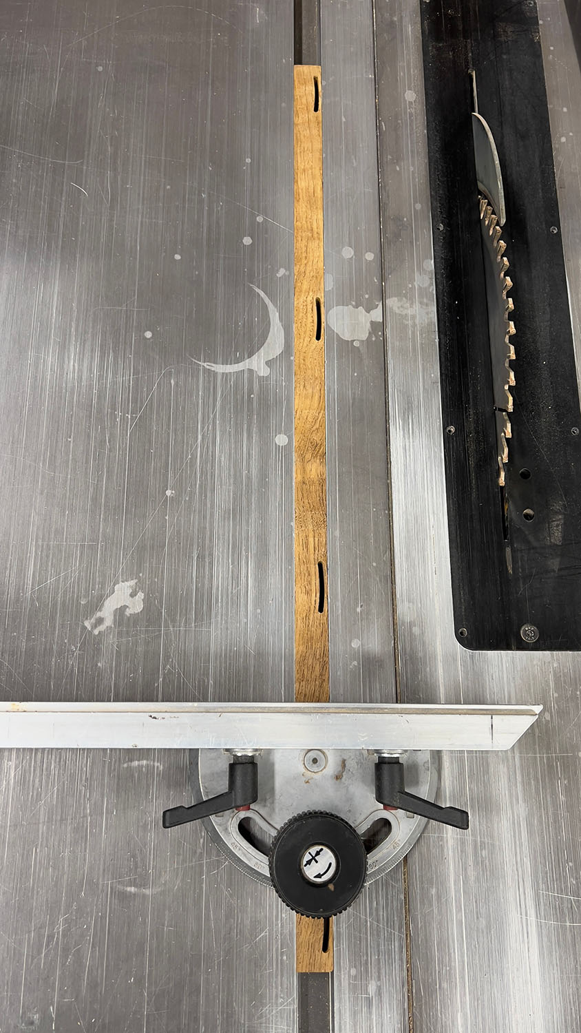
The runner I cut out of wood is dimensionally accurate.
Using the same files, the runner I cut out of UHMW is too big, again. Over 20mm, it’s about 0.5mm too big.
The only thing I can think of is deflection. The piece is stuck down to the table really well (have to pry it up to remove it when done), so maybe I’m not taking an aggressive enough cut and the bit is just rubbing against the UHMW?
Was doing climb cutting. I’ll have to go back and look over my toolpaths to see what I’m doing with regards to roughing/finishing, but thought I had at least two passes there. What is a good value for Stock To Leave after the roughing pass? Maybe I’m leaving too little?
OK, with what I’ve just learned about milling aluminum and chipload, etc. , I’ll build all new toolpaths, starting with an adaptive in F360 and see where that goes. Still weird that teak milled just fine by UHMW is off by so much (and yes, half a mil out of 20 is a lot).
Yes, same .nc files and same cutters. After seeing this problem earlier, I re-created all the toolpaths from scratch and then decided to test in wood since I had scraps. That turned out fine, so I then cut the UHMW and was surprised to see this difference. It’s a head-scratcher.
EDIT: Jason’s comment below made me realize I was wrong in saying “same cutters” - I’m using the Carbide3D/Amana O-Flute for the plastic and the 201,etc for wood!!
I looked up “UHMW plastics properties machining” and got an AI answer saying the material has a max service temp of 180 deg F .
I think the material is distorting and not coming back.
Machining considerations
Cooling: Use air, water, or a cold air gun to prevent melting and gumming.
Tooling: Use sharp, high-quality tooling. Since it can cause wear on dull tools, it’s best to use bits dedicated to plastic or that have not been used for metal.
Feeds and Speeds:
Feed Rate: Use a fast, aggressive feed rate to clear chips efficiently.
RPM: Operate at lower RPMs, typically between 1,500 and 2,000 RPM.
Warping: A common issue, especially with large parts.
Solution: Use a step-by-step machining process to release internal stresses gradually.
Fixturing: Use large-area adsorption fixtures or vacuum tables to clamp parts securely and minimize the risk of warping.
Chip Evacuation: Use methods or equipment to ensure chips are removed from the cutting area as they are produced.
I think it’s distorting and then coming back after the cutter passes.
I made this small block today as a drill guide. Since I had a small piece of UHMW scrap, I used that. Even though it’s only 12mm x 75mm, the block came out about 12.4mm wide, but the two holes spaced 35mm apart were dead on 35mm apart. Here’s the small simple Fusion file, but I’m pretty sure it’s the material and I need to be more aggressive with the cutter.