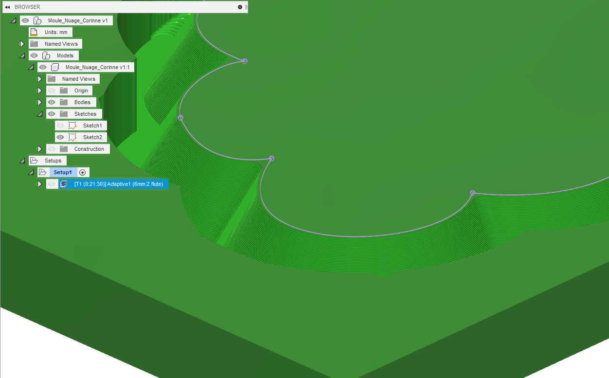
I have this cloud-shaped piece, that I intend to cut with a roughing toolpath using a 6mm square endmill (result of the simulation of that first pass below), and then run a finishing pass of some type to shave off the remaining material.
I could use a ball endmill, but I wondered if I could use a (small angle) Vbit as the finishing tool, to get inside those sharp angles. Can someone enlighten me as to which 3D toolpaths are compatible with a Vbit, and whether that idea makes any sense?
If this is silly, I will just use a tinier ball endmill, just wondering if the Vbit approach for finishing a slope is supported.
I’m not sure of the end goal, but could you just do a “regular” V-carve island to achieve the chamfered edges?
If your’re just going for an angled look and you’re ok with a 90 or 60 or whatever being defined by the bit geometry, it would be possible to get a great finish.
It is not silly at all. There are a number of options.
The easiest is 2dcontour with a chamfer bit. This will not get the narrow concave areas if you want the form modeled exactly, but will be close with a small bit that comes to a near point IF the height is small. Have the contour follow the bottom edge, and, with properly define tool geometry, Fusion will compute the offset correctly.
You can tighten it up by defining a set of curves on the surface closely spaced in Z, following each as a contour, and, if the remaining steps are an issue, run a small ball end down the root of the concavity (I do this by defining a path-- a line-- on the surface down the gulley, and contouring it with appropriate stock to leave for the needed offset. A good simulator is nice, but test pieces are key). I have not done this exact circumstance, but have done similar setups for optical mounts (admittedly using Inventor, but the capabilities are the same here)
@enl_public thanks for the pointers, I’ll experiment. @neilferreri sure, I’ll share the file later today. This is to cut a pottery mold for someone, from a paper sketch. I’m trying to make it the exact geometry specified mostly as an exercise, but using a 60deg Vbit might be close enough, I’ll fall back to that if smooth finish is more important than geometry.
I think most of the toolpaths can use a tapered endmill, you can even 3d adaptive with a V bit lol. Its important to define the flat on the end if you want to do that for opt load specs.
$0.02 - rough it flat, plug in the tapered and ramp that sucker in
Is the depth of the carve deeper than the V bit can take in one pass? If not you could create an offset from the cloud sketch and use that as a profile pass. That’s not really the “right” way, but I think it would work in a pinch. Vince’s option sounds more like the correct way to do it.
@themillertree: yeah I need to cut deeper than my V-bit width allows, and anyway the chamfered edge is not exactly 60deg. If I end up using a Vbit with a regular Vcarve operation, I will probably do it exactly as you describe.
@MarkDGaal, @fenrus: it seems like a good workaround indeed (faking a tapered/chamfer bit), I was just surprised that Fusion360 would not accept using a Vbit for these toolpaths. I’ll check how my Vbit is declared in the tool library, to puzzle this out.
I’ve been really frustrated by how hard it is to use such a useful tool (and yes, I feel bad that @fenrus has worked up a tool which may address this, but I’ve been too busy w/ tech support, day job, and fixing graphics, and trying to make a box to try it out). Kind of relieved to know that Fusion 360 doesn’t address this and that I don’t need to feel badly about not using it.
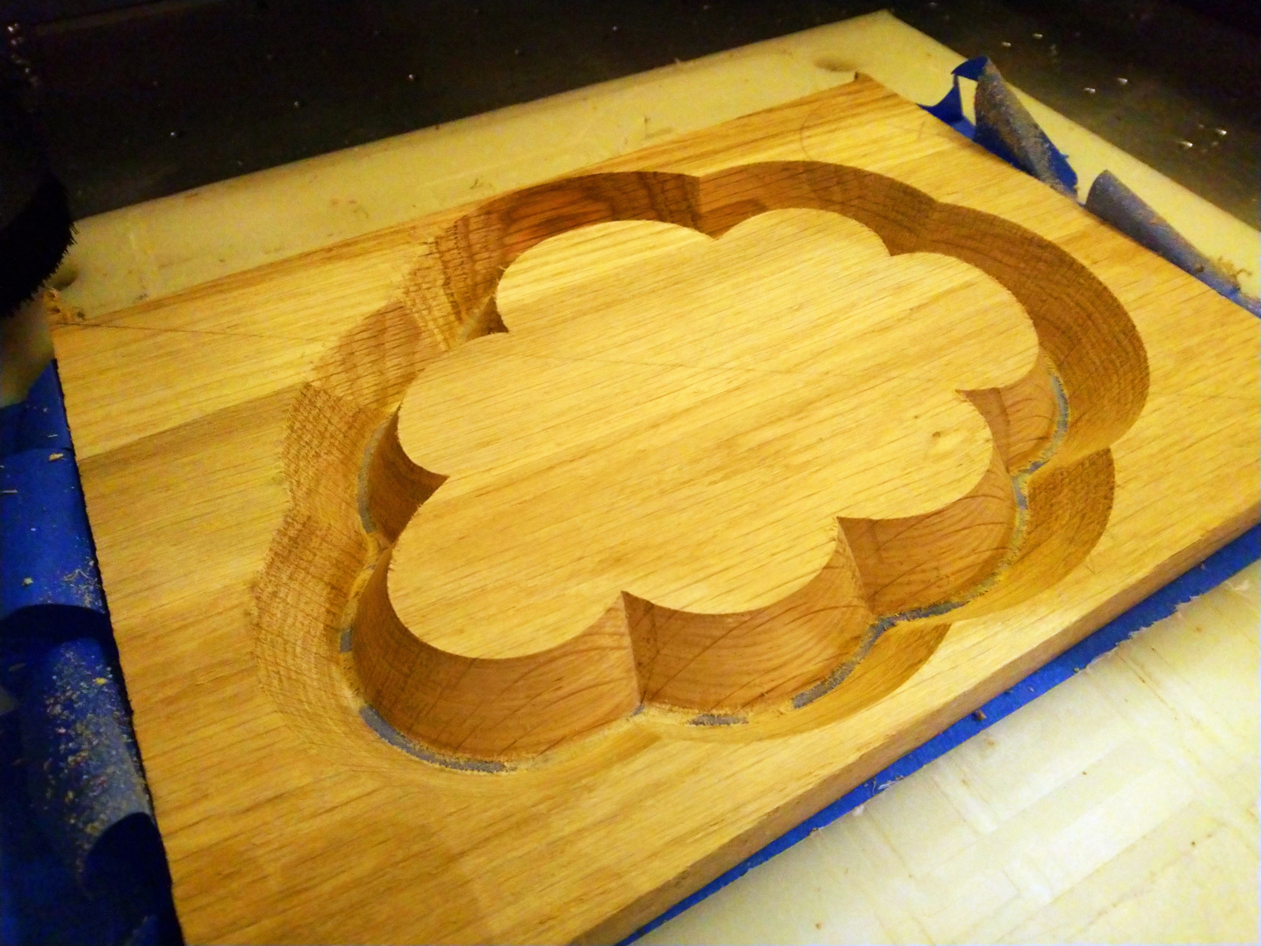
So I ended up being lazy and going for the 60deg Vbit approach…which in hindsight is what I should have done from the start, since the model chamfer angle was close enough to 60deg that the difference does not matter.
It’s a computational thing. If the path is known (like with 2dcontour, for example), and the tool profile is known, computing the final surface is practical, even if the tool profile is not simple.
If the tool profile is known, figuring out the path to produce a particular surface on the work is hard. If the tool profile is not computationally easy (portion of a sphere, portion of a cylinder, bull nose, and so on), it is impractical. Evan a 45 degree chamfer bit (90 deg vee bit) is hard, in an X-Y-Z world.
I found that if the surface angle matches the bit exactly, some tool paths will be successful, sometimes,-- I spent way too much time trying different things-- that fail if the angle does not match.
I don’t know all of the details, though if I were in school now it might be an area I would pursue. So much cool math.