So I normally use Carbide Create for all my machining needs. I now have a part that is just too complex and needs advanced tool paths. So I am trying to get my S5 to work in Fusion360. When I search for information on getting it setup I see @WillAdams’s posts pointing to this FAQ:
I believe @wmoy goes over using Fusion 360 in some of his videos.
That said, have you considered some other tool? I’ve been successful w/ Alibre Atom3D in the past (and need to get back to running it, esp. now that I have a Connexion Spacemouse…)
I have found all kinds of tutorials on using Fusion360. What I was specifically looking for was how to configure fusion to specifically work with a Carbide3D system. I had been looking in the Machine Management section. I just realized that you actually just need to go into the Actions → Post Process part and choose the Carbide3D post processor. I just think that this is definitely worthy of a spot on your FAQ page and am a bit confused on why it was removed.
There’s a few threads where we’ve discussed trying to use the Fusion machine models (mostly with @neilferreri 's help) but mostly determined it was more bling than actual use to us.
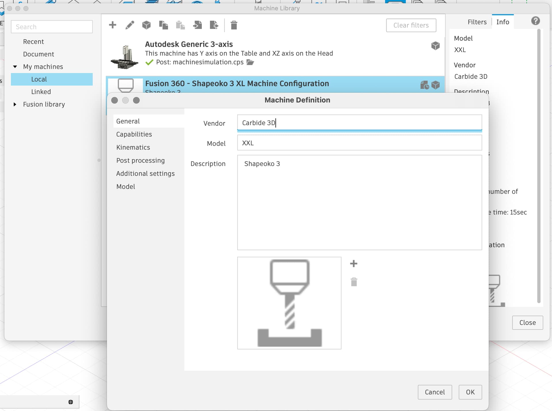
You can create a “machine” in the library for you to select rather than just the post processor.
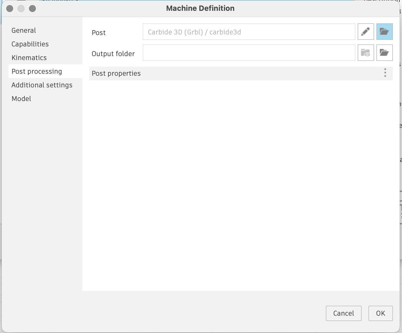
You’ll need to select the Carbide 3D post processor (or I think Neil may have an improved one). You can also set your default post output folder here which can be handy.
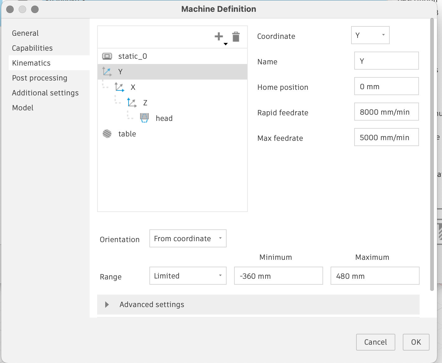
You can set the X, Y, Z movement ranges, but I think this is only relevant if you’re doing the machine simulation thing, which I’ve not bothered to do.
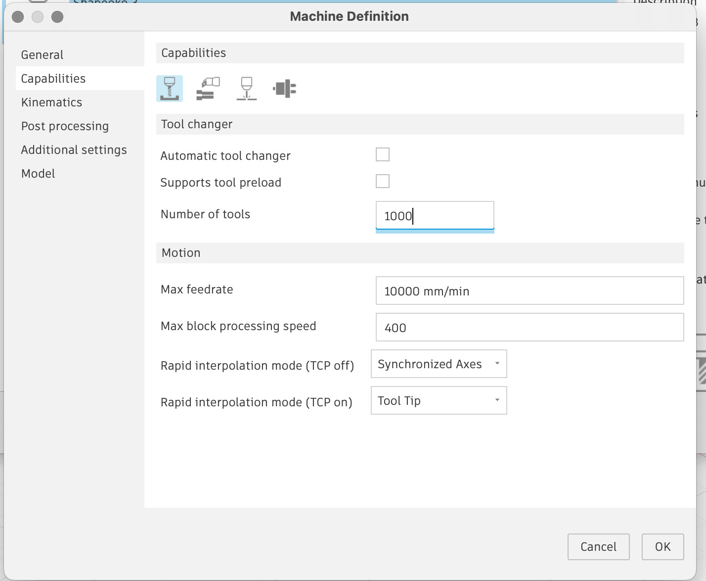
I find it useful to tell Fusion that it has a 10,000 tool changer as I’ve used four digit numbers for my Tool IDs based on the vendor’s part numbers, that way you don’t get a yellow warning saying you’ve selected an invalid tool ID on your Post.
use NCPrograms to group same tool, toolpaths or group same tools to use in step 1, step 2 etc
using NCprograms also useful for folder output, filenaming and post processor, and rerunning post processing, and simulations
creating manufacturing models in order to layout parts, repeat parts, add or remove features like adding tolerance clearance to grooves on oneside with a cutting extrusion without impacting the design. Removing chamfers to aid pocket selection.
adaptive paths for metal cutting.
cutting ramps
modelling complex parts or parts variations; e.g. number of holes, similar boxes different dimensions
I have actually started suppressing the chamfer in the design before moving into the manufacture workspace. That Way I can visualize the chamfer, then I use the quick chamfer toolpath for the chamfer. That way I get the ability to select pockets easier. That is supposing that it is a nice 45 degree chamfer though.
Well my first Fusion toolpath came out amazing. There is a big learning curve on optimizing things though. I think a quick, up to date getting started with Fusion360 and a Shapeoko would be great. I was finding all kinds of outdated stuff for a bit there.
Are you looking for help using Fusion 360? Or running the F360 file on your S5?
I use F360 almost always, now that I’ve gotten through the steep learning curve. For everything except inlay work. Once F360 generates the g-code, I just use the UGS app to transmit it to me Shapeoko.
Hi. Could any of your guys bottom line this process, or point me to a resource?
I’ve been using Fusion for Design for 3D printing forever but just now moving over to Manufacture so I have some learning curve there. What would be helpful is just the 50,000 foot view, something like;
“All you have to do to get Fusion working with the Shapeoko 5 is add the carbide3d.cps in post processing, then blumity blump setup in foo and then go do all of your work using x,y,x tools in fusion, the do bipity bip to generate the code and send it to the machine using bipbap”. Excuse my use of highly technical terms ;->. What do I need to do in Setup->New Setup if anything?
Thanks