We are using Fusion360 and a Shapeoko 3XXL. We are having some weird toolpaths that are kinda offset from what the G-code shows. We are basically cutting a contour of a rectangle but the toolpath does not end where it began. It is offset by about 1/32". It is so weird. The Gcode looks correct but it consistently cuts with the offset. G-cade is attached,
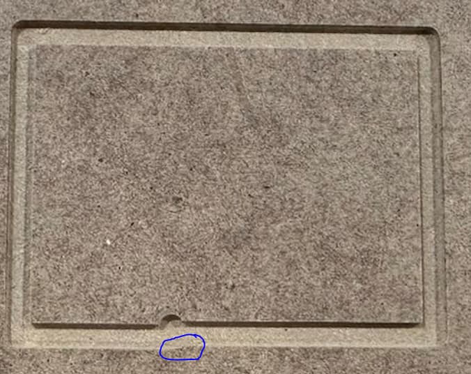
Here is a picture of what we are getting.
Yes, but you’re cutting it as a slot — adjust feeds and speeds, use a smaller tool and try an adaptive/trochoidal toolpath, or otherwise adjust things.
Yes, try holding a pen vertically, then drawing a similar shape and consider how friction alone makes this difficult — then consider having to actually remove material.
To me it seems like a error in 2d pocket, the toolpath is determined to bite a chunk out of your stock. I tried a bunch of tweaks and nothing would fix it.
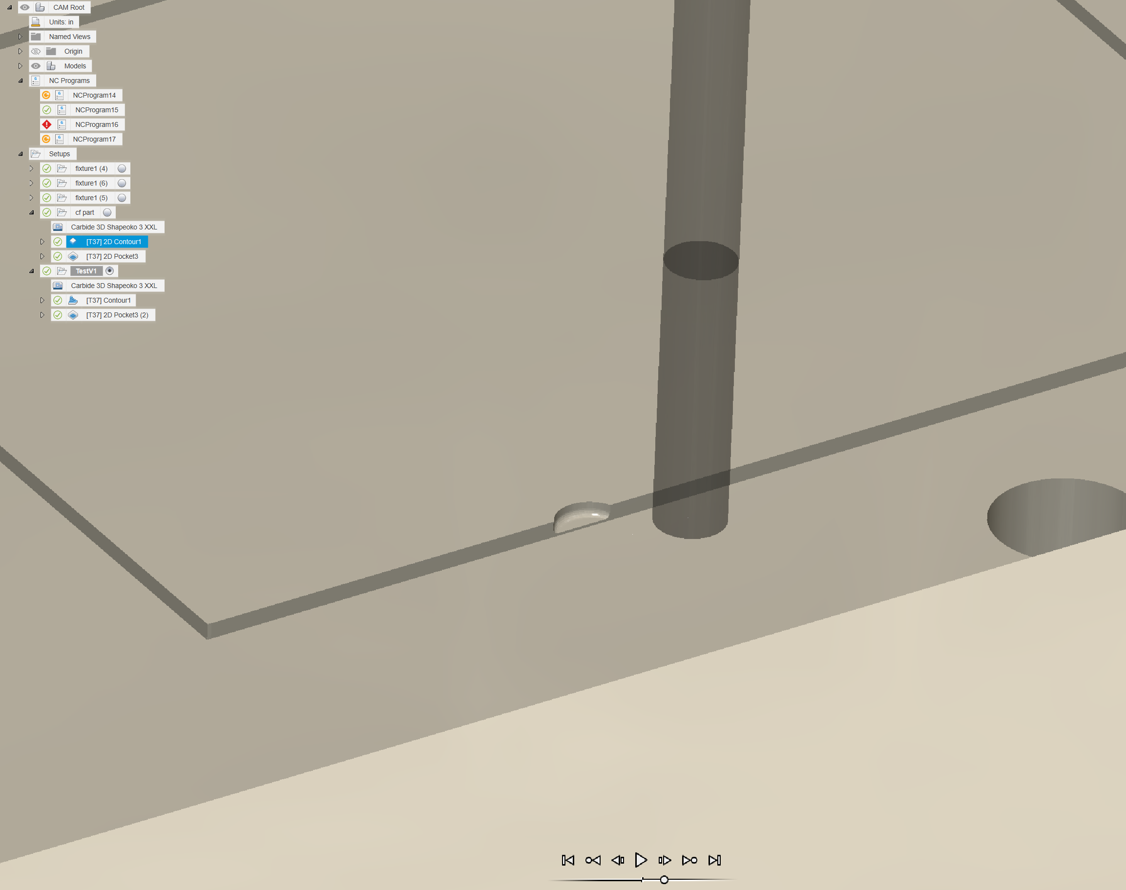
I made a 3d Contour file with a plunge entry that I think accomplishes what you were working on, please check out/simulate the file thoroughly before trying. Carbon_TestV1.zip (492.6 KB)
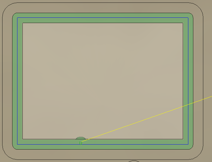
Contours in fusion 360 have an “inside” and an “outside”. This is represented by the red arrow when you select a contour. If you look at your contour of the big square, the arrow is on the inside side of the contour. That indicates that the inside of your square is the “outside” . This is particularly important for lead-ins/outs as well as if you want to take multiple passes.
Each operation has lead-ins / lead-outs that are the strategy used to slowly engage the tool into the stock and to exit the stock. Your contour’s lead-in is the cut that you are seeing that you don’t want. It leads in from the middle of the block because that’s the outside.
A simple solution would be to simply reverse which side is inside and which is outside. To do this, open the contour operation and under geometry select the path you want to change. Note the position of the red arrow and click on the red arrow to cause it go to the other side.
That said, if I was cutting out this slot, I would probably do an adaptive toolpath to remove the bulk of it but leave a small stock behind and then come back with the contour and a flat operation to clean up the stock that you left behind in the adaptive clearing.
As @crpalmer indicated about the lead in/out the issue you are chasing down seems to be the lead-in in your “cf part” “[T37] 2D Contour1” toolpath. If you run the simulation you’ll notice the bit plunges into the material and then moves over to follow the selected contour.
I see it as tool deflection. You’re cutting with an 1/8th inch bit, and between the bit and the belts you’ll have some. Myself, I would leave a little stock, and come back with a finish pass.
Thanks Quicky06! We bought machine from someone and should not have trusted their assembly. Those pulleys are the one thing we did not fully look at. We aligned and tighten all of them and problem seems to have gone away.
Oops, my mistake. I saw the lead in and assumed that was the toolpath problem that you were trying to resolve. I really need to read more closely in the morning!
Glad to hear that it sounds like you fixed the mechanical problem.
That said, the chipload looks really low to me. I just double checked and I see that you are using the speeds and feeds provided by Amana (in their fusion tool library). However, I would have expected a 10+ times higher chipload. Being curious, I found a video from NYC CNC which uses much higher chiploads (https://www.youtube.com/watch?v=Ucv3nDgmf3o – the feeds and speeds are in the description).