There have been a bunch of times when I’ve wanted to do something simple like face some stock or do a contour but I’ve been too lazy to open up CAM.
I could buy G-Wizard Editor and use its conversational CAM features but it costs $300.
However I spent a bunch of money on this fancy controller board that supports a G-code dialect with nice features like flow control, so I thought I’d try to use that and what do you know, it works pretty well! I thought it might be interesting to share and show people here a couple of macros so they can see what they look like. Even if you can’t use them, it’s still interesting.
First though, some basics:
- Anything that comes after a
;is just a comment. The controller ignores it, it’s there to make the G-Code easier to read. - In my controller, things that look like
#number, e.g.#33, are variables. These are placeholders that you can set to whatever you like and the controller will remember them for you. For example if I tell the controller#30 = 1234and then tell the controllerG1 X#30, the controller remembers that I told it#30means1234and interpretsG1 X#30asG1 X1234 - When there are things in between
[], that just means logic like addition, subtraction or comparison is happening inside the[]. -
While <thing> <more stuff> Endwhilemeans "as long as<thing>checks out, do<more stuff>. - You can ignore anything with
subin it for now.
So here’s the code:
sub face
    ; X max: #30
    ; Y max: #31
    ; Z cut: #32
    ; Z retract: #33
    ; Z feed: #34
    ; Feed: #35
    ; Stepover #36

    ; Go to a safe Z height
    G0 Z#33
    ; Go to the bottom right corner of the stock being faced
    G0 X[#30] Y0
    ; Start the spindle
    M3 S10000
    ; As long as the position on the Y-axis is less than the maximum, do the stuff below
    While [#5002 < #31]
        ; Plunge into the stock at the plunge feed rate
        G1 Z#32 F#34
        ; Cut from the right side of the stock to the left side of the stock
        G1 X0 F#35
        ; Retract to safe Z height
        G0 Z#33
        ; Rapid to the right side of the stock, but up one step on Y
        G0 X[#30] Y[#5002 + #36]
    endwhile
    M5
endsub

gosub face
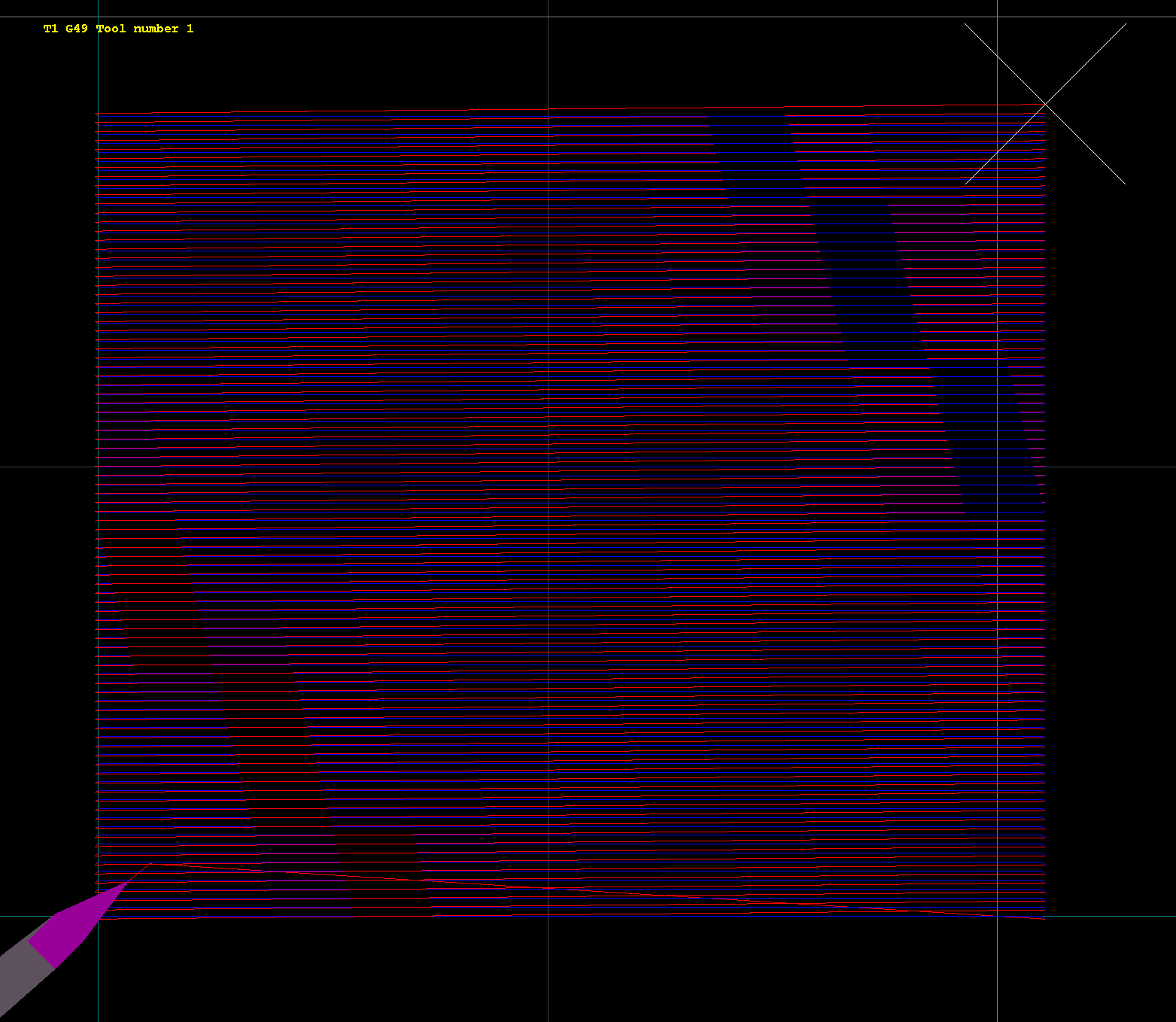
And the toolpath looks like this (red is rapid, blue is feed, pink is where rapid and feed overlaps):
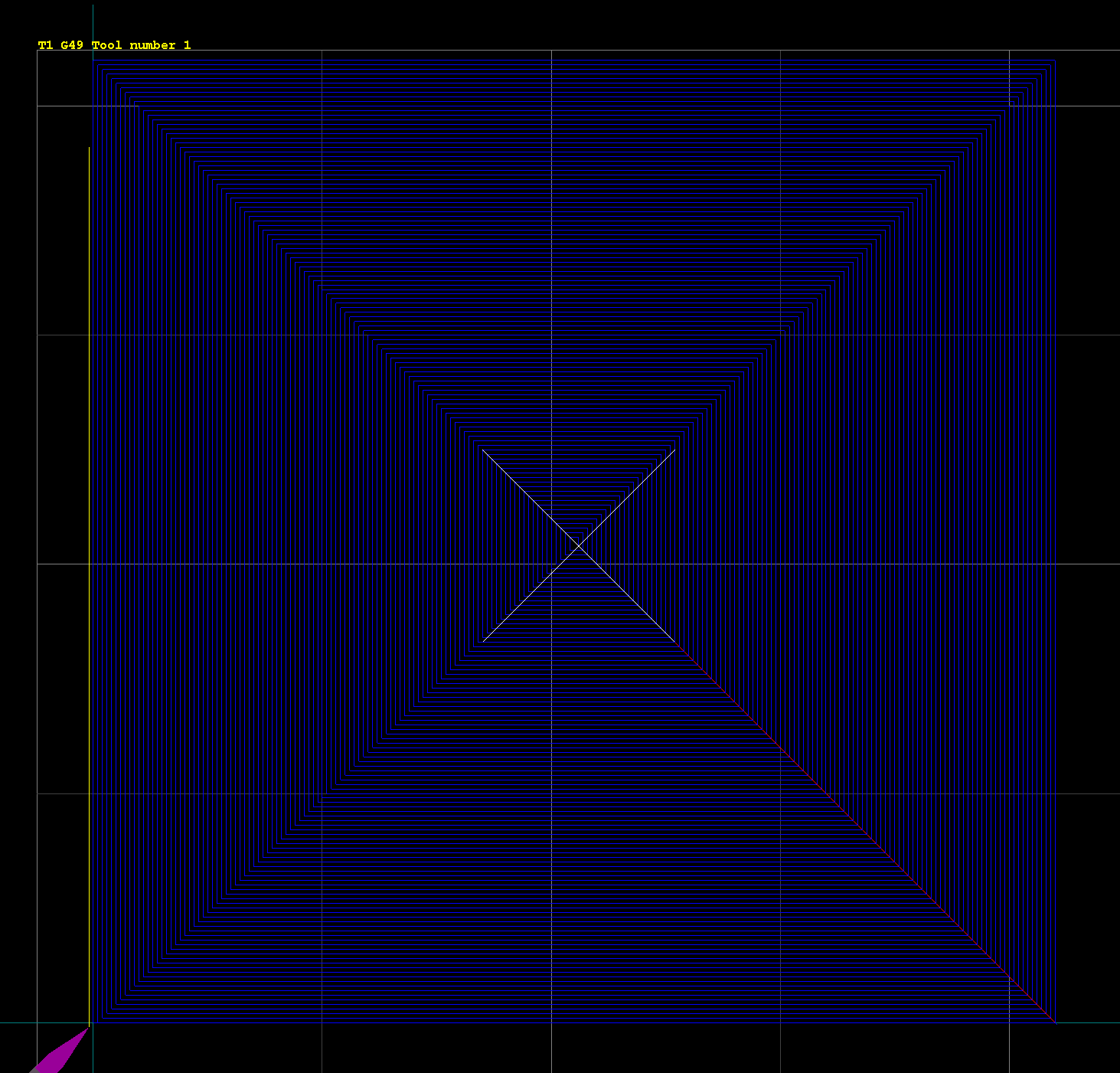
And for a more complicated macro, here’s another one that faces a stock in a spiral pattern.
The way it works is by cutting a rectangle, then cutting a smaller rectangle inside the first rectangle and repeating.
; Stepover
#30 = 1.0

; These numbers keep track of the edges of the square (stock)
; Left of stock
#31 = 0.0
; Right of stock
#32 = 210
; Bottom of stock
#33 = 0.0
; Top of stock
#34 = 210

; Z-retract
#35 = 1.0
; Z cutting height
#36 = -0.05
; Feedrate
#38 = 300

; Retract to safe height
G0 Z#35
; Go to the bottom right corner
G0 X#32 Y#33

; Start the spindle
M3 S10000
; Set the feed rate
F#38
; Plunge into the stock
G1 Z#36

; Figure out whether there's still a rectangle to be cut. When the top meets the bottom and the left meets the right, there's nothing else to be done.
While [[[#32 - #31] > 0] or [[#34 - #33] > 0]]
        G1 X#31 ; Go left
        G1 Y#34 ; Go up
        G1 X#32 ; Go right
        G1 Y#33 ; Go down

        ; Shrink the square by bringing each of the edges <stepover> closer to the center.
        ; Bring the bottom edge <stepover> closer to the center
        #33 = [#33 + #30]
        ; Bring the left edge <stepover> closer to the center
        #31 = [#31 + #30]
        ; Bring the top edge <stepover> closer to the center
        #34 = [#34 - #30]
        ; Bring the right edge <stepover> closer to the center
        #32 = [#32 - #30]
Endwhile
And here’s what the toolpath looks like:
As for why all this matters, once you’ve set up the macro, you can add it to the controller’s startup file and then, using that sub thing, reference the macro by name.
For example if I want to use the first macro, since I wrapped all the G-Code in sub face, I can reference that macro using the name face. When I want to face some stock, all I need to do is set the variables (which I can do in my controller’s UI) and then invoke gosub face in MDI.
