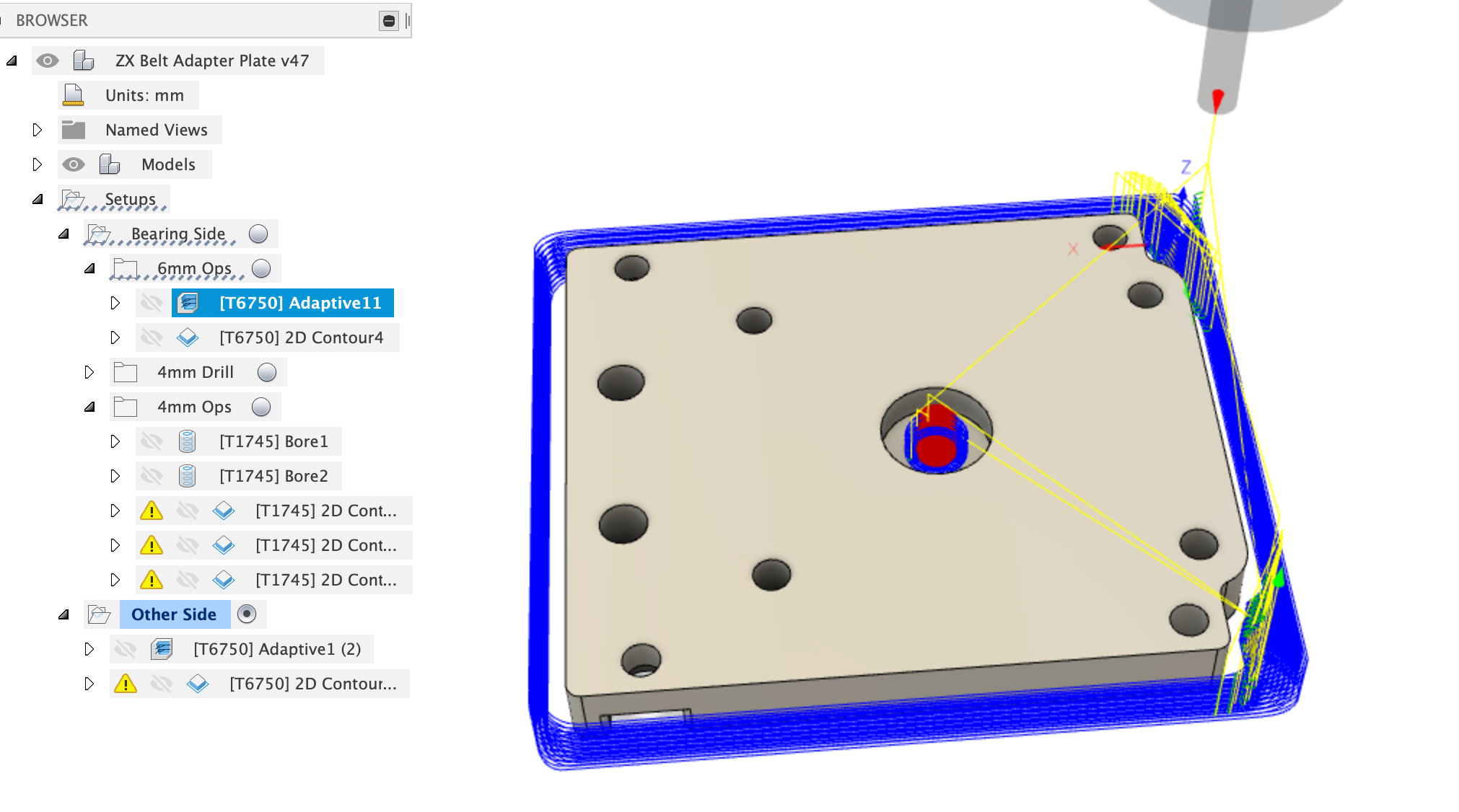
I’m making some first Aluminium cuts with my Shapeoko and picked up some single flute cutters for the job, using one of these;
a cutter described as both end mill and slot drill, it cut from the sides absolutely fine in adaptive clearing, 2.5mm DoC, 800mm / min and 0.5mm WoC.
However, when it then started a helical ramp into a pocket,
1 degree ramp angle
5.7mm min ramp dia
200mm / min ramp feedrate
20,000 RPM
0.01mm feed per tooth
It made an unpleasant knocking, clonking sound of trapped chips as it worked down the ramp. The ramp angle and feedrate were initially higher but I backed them off to those above. I ended up having to drop the spindle to 10,000 RPM and feed override to 20% to get the ramp to cut without donk / clonk from the cutter.
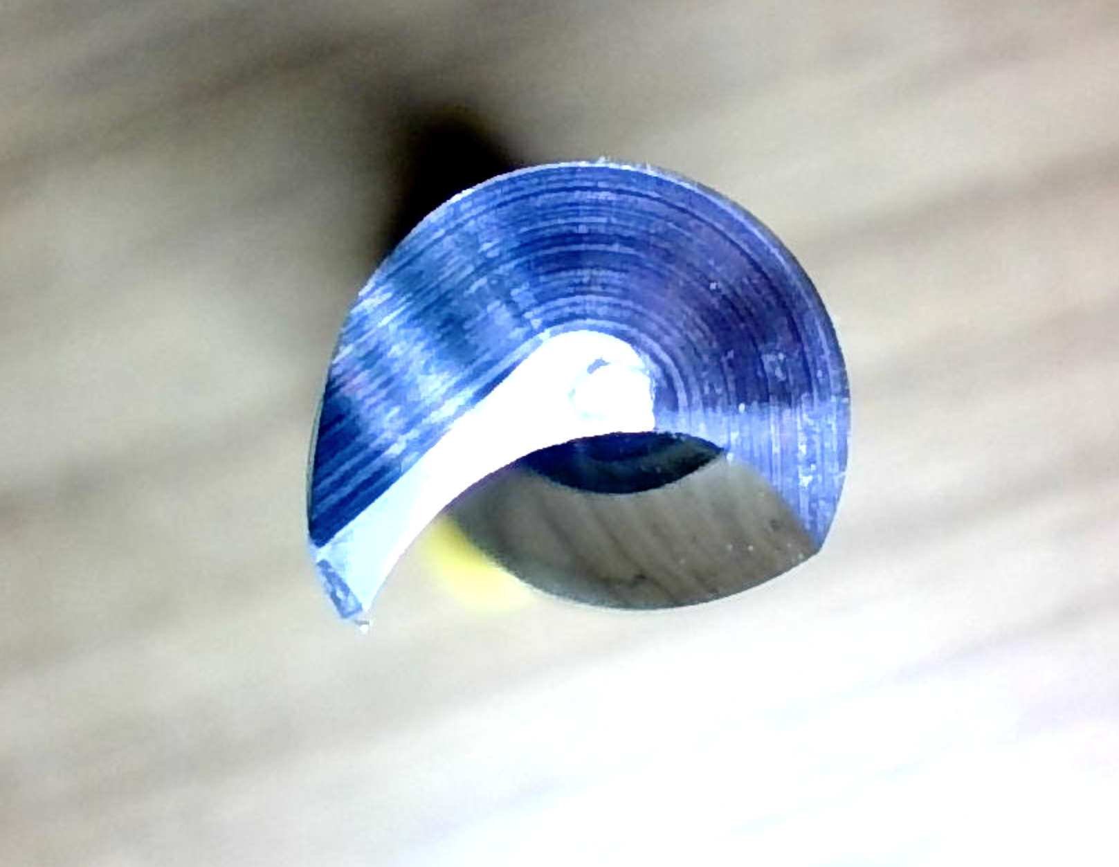
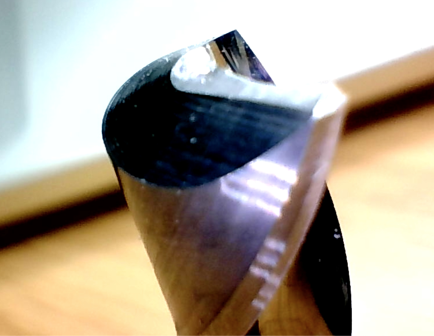
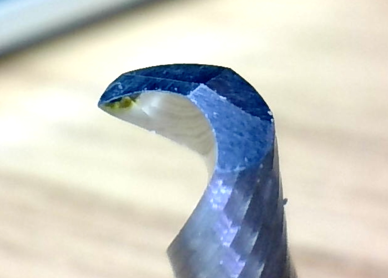
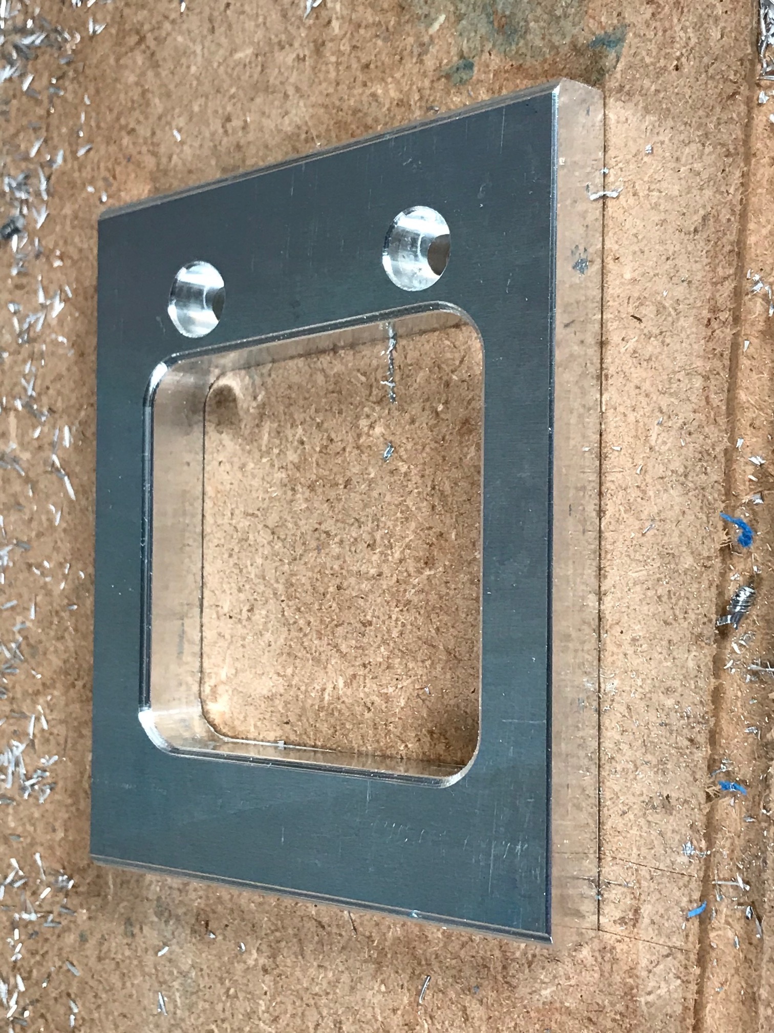
Here’s the tip of the cutter, I’m not sure it has appropriate face geometry to be able to plunge or accept any notable helical ramping, thoughts from those with more experience of inspecting cutter geometry pls?
As it happens, I decided to pre-drill the holes with a 4mm carbide spot drill that I had on hand, the spindle was perfectly happy pushing that into the 6061-T6 at 3,000RPM and making nice starter holes for the 4mm little brother of the 6mm bit above.
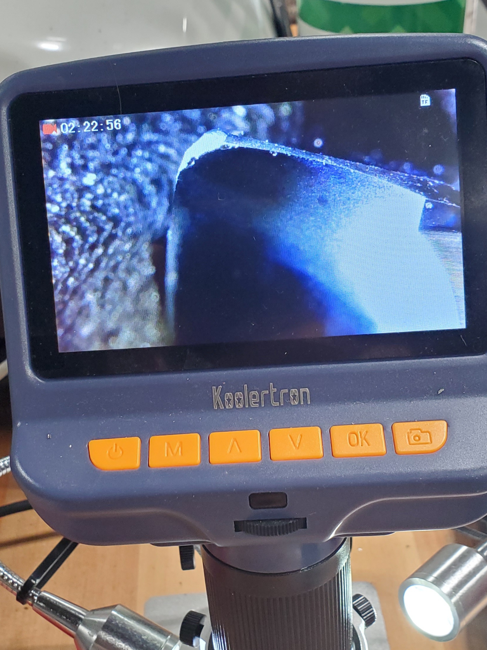
I stopped the helical ramp a couple of times as it was cutting and the bottom looked smeared rather than cut, just as if the tool couldn’t cut on the end. As soon as it finished the ramp and went into cutting the walls it was fine again. I did everything else by pre-drilling with the spot drill
There was very little chip in the hole during the ramp, the noise started less than 0.5mm into the hole and the dust extraction was clearing up the chips as they were thrown out by the cutter. That was about 10 mins after coming out of the box and the cutter has only run on this part.
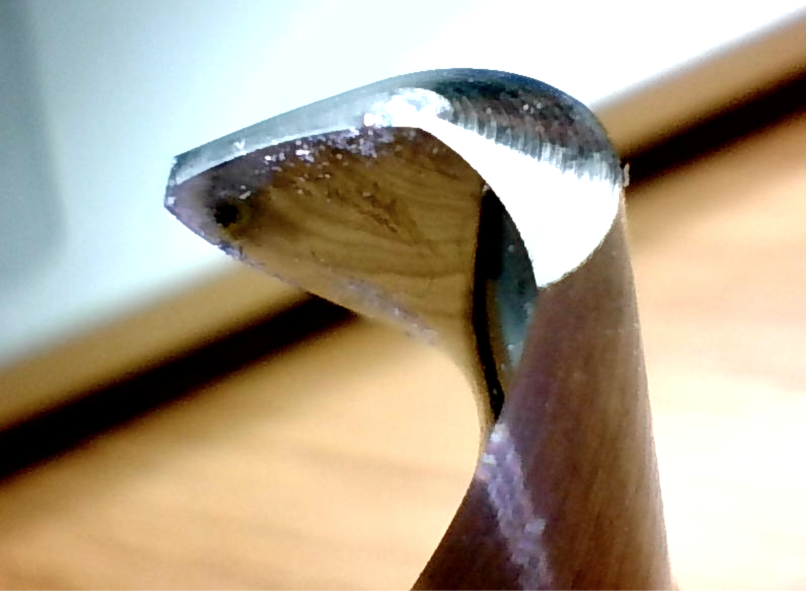
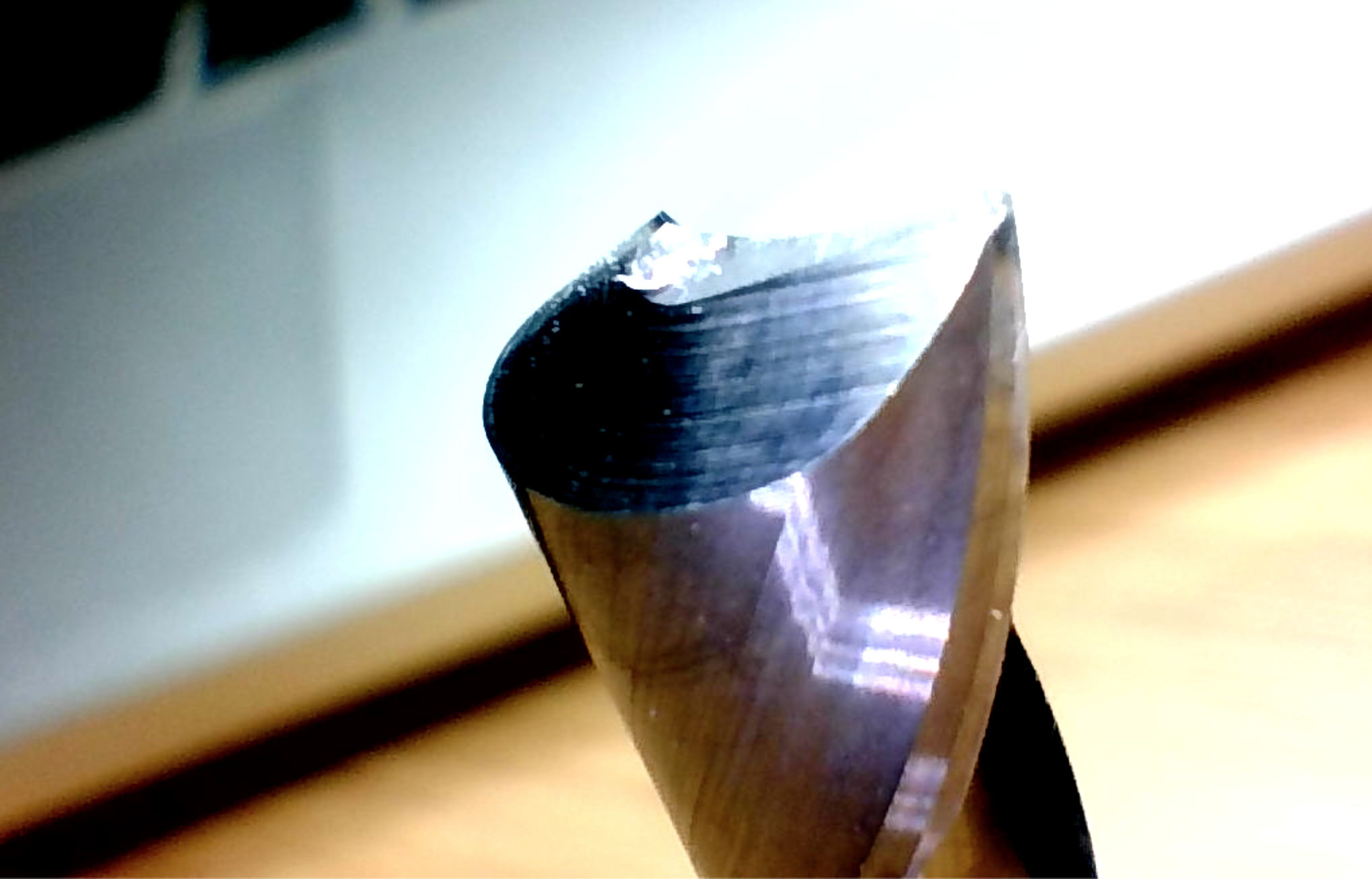
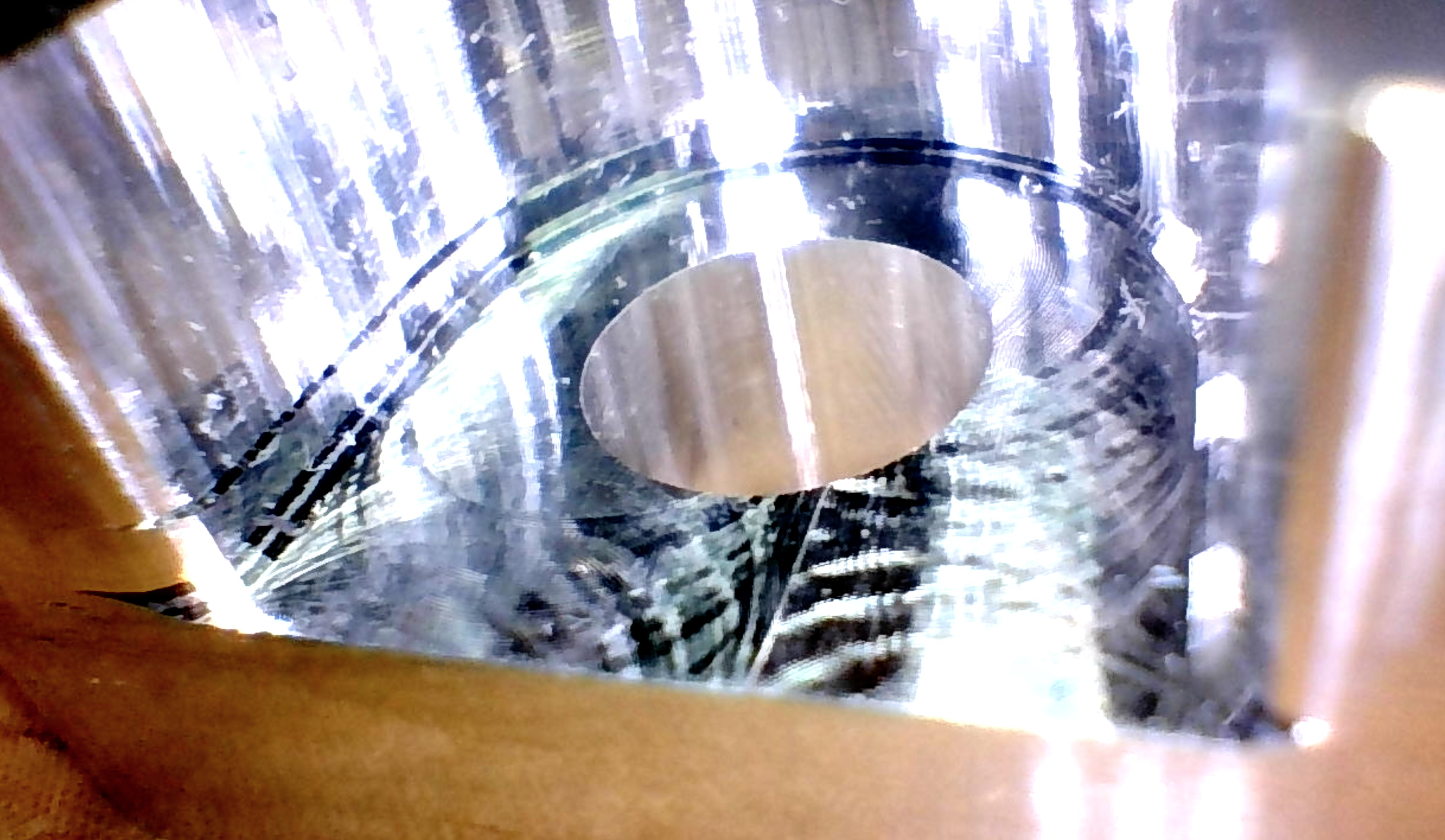
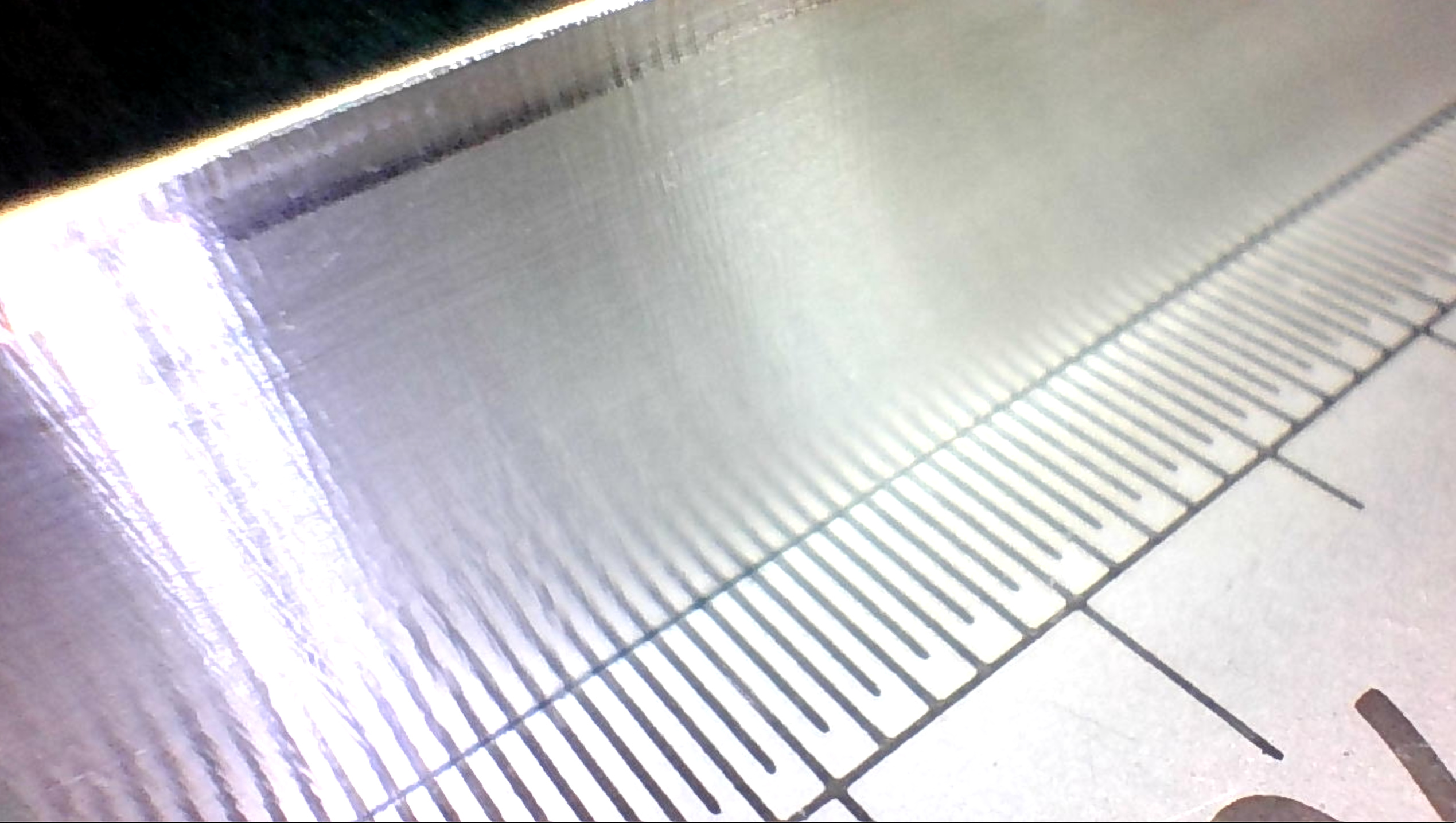
And here’s the bottom of a pocket from that same cutter about 2 toolpaths later (Other Side). I can see the step in the corner where the chipped off corner is (now that Mike pointed it out);
Effect. This is a feed and speed issue. The problem with the single flute cutters is that the edges are kind of prone to this, but they have gobs of clearance for chips. I haven’t been able to get this 100% right myself, but @Vince.Fab might have some guidance.
I’ve emailed a couple companies about making a custom radius tip SF. As far as I know, nobody has one.
I actually tried to grind my own (first time ever) to save a pricey end mill. Worked decent but pushed a small burr and you could tell it wasn’t cutting as efficiently.
It seems that everyone makes their geometry a little different. But in the end, SF live a hard life on these routers. High rpm, high forces, high chiploads, and chatter. Most will chunk a tip like that on one bad crash.
It’s still cutting on the side quite happily, It ate it’s way through the stock to find this part today, adaptive clear at 800mm/min, 20kRPM, 3.2mm DoC, 0.5mm WoC and was quite happy, so yep, rougher it is
The 4mm brethren of that 6mm cutter don’t seem very happy ramping in to this plate either, it’s surprisingly hard, I can’t even get my M8 tap to cut a thread in it. Wherever I can’t come in from the side I’m pre-drilling with the 4mm spot drill and then telling the adaptive clear where the pre-drill is, that seems to be working for now. I will now stop thinking of Aluminium as a ‘soft’ metal, it’s definitely closer to Trivium than Def Leppard in these hardened alloys
Putting the holes in the ends of this part has also told me that no, my front vertical clamp for woodwork isn’t good enough and yes, I do need a real machine vice to put on the spoil board.
Those edges look very nice so you have to be doing something right! Also bomber job on those chamfers! care to reveal your strategy?
If you look at the K factors of 7075 and 1018 steel, you’ll find them pretty close! I’d actually have to say that AL might be a little tougher because it needs a much bigger chip to prevent bad things from happening.
Vince said my part looks good! (does a little dance)
As for the chamfers, erm, they’re a bit of a mishap, sorry. They were supposed to be round fillets but something went wrong. I was using a 3mm 2 flute ball end mill with a ramp strategy and 0.25 stepdown but I think the Z probing must have been off by 0.2-0.5mm as the first cut was a bit heavy.
So what I’ve got is a bit more woodwork than metalwork, there’s the roundover and then a little wall up to the surface, it does give a nice reflection pattern though.
The mirror pair of this part came out with fewer mistakes, it’s still not right but there are fewer mistakes this time, the fillet is still not properly round, I should just use chamfers wherever I don’t need a round or buy a roundover bit;
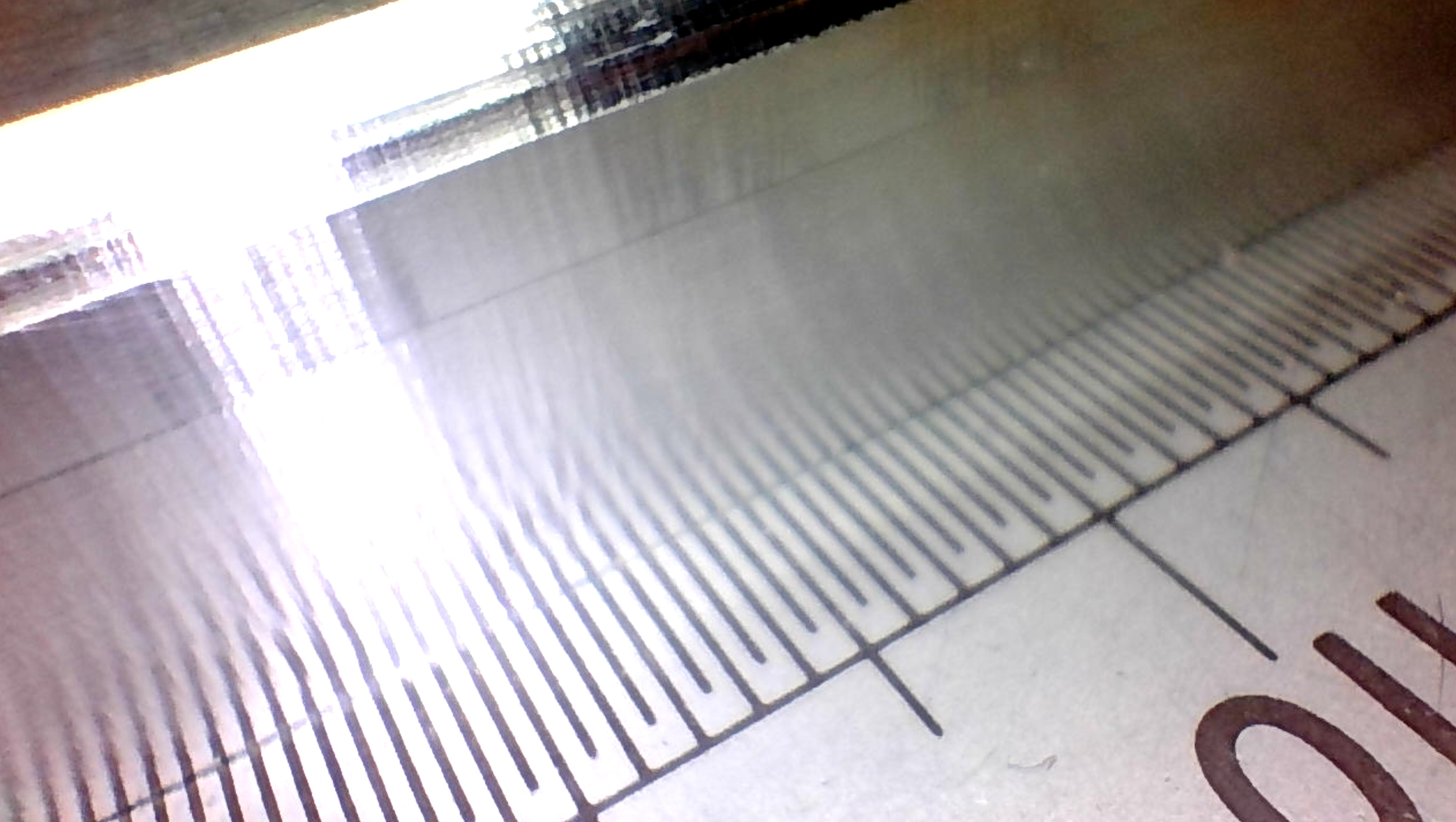
What may be interesting to folk is the difference in surface finish between traversing X axis where the HDZ is reasonably stiff in side to side rocking, this is way better than I expected to get, to the hand it feels like glass;
vs. traversing Y where the V Wheels allow quite a lot of ‘nod’ where Y and Z deflection is coupled, still feels smooth but the chatter is visible there, although it sounded smooth in the finishing pass;
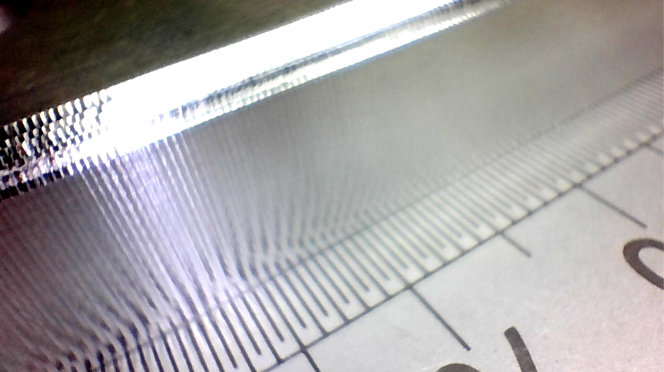
and finally the 5.5 degree angle on the side where what I believe to be the X step size is visible, echoes of Juliens acrylic wall finish odyssey here.
Overall, for a £12 cutter which I already broke the tip off, I’m really impressed with the wall finish.
I gotta say you have surprisingly good finishes! It’s tough to get the “wattery” look out of 3d finishing passes. You might be interested in how this one runs