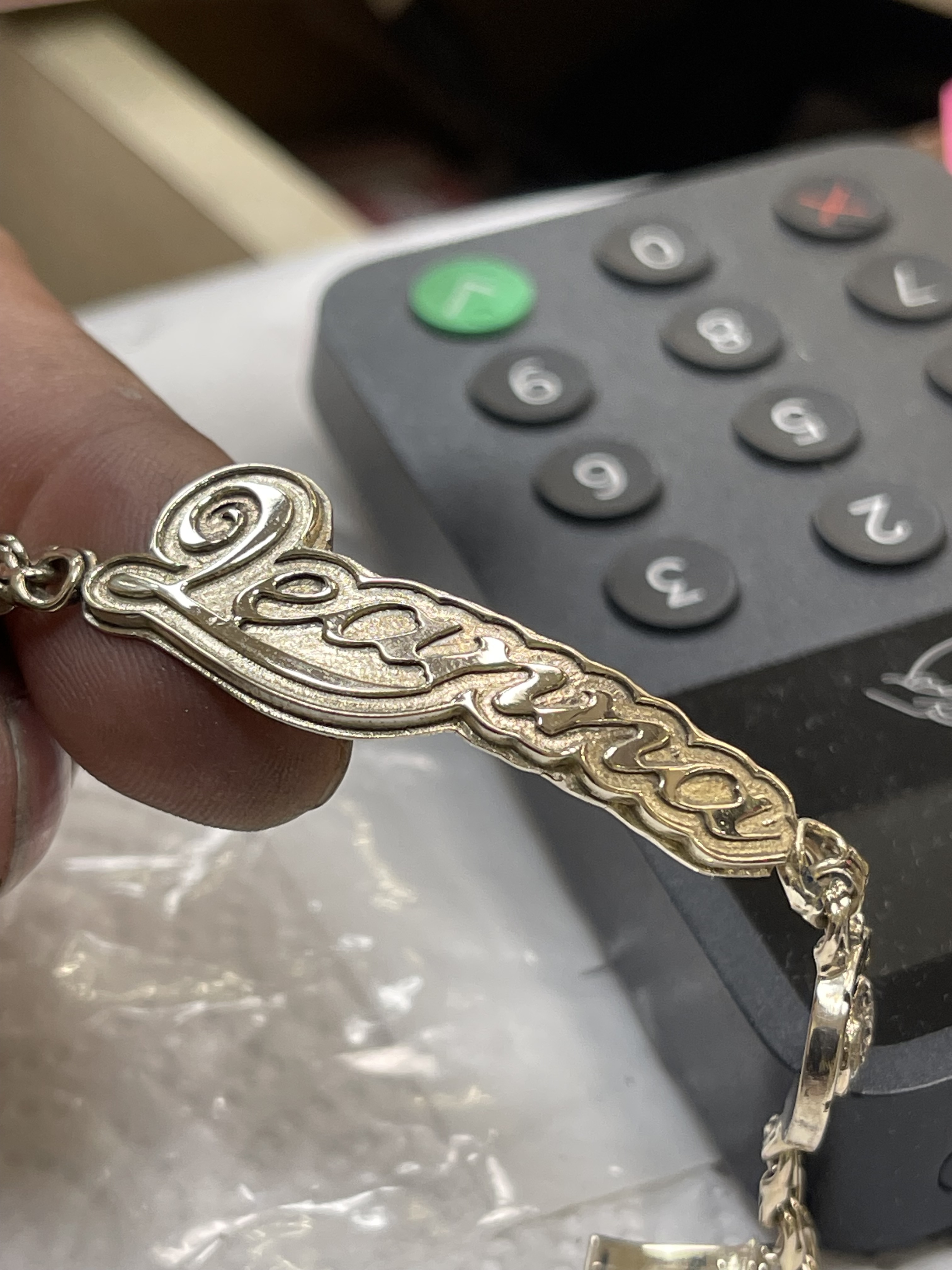
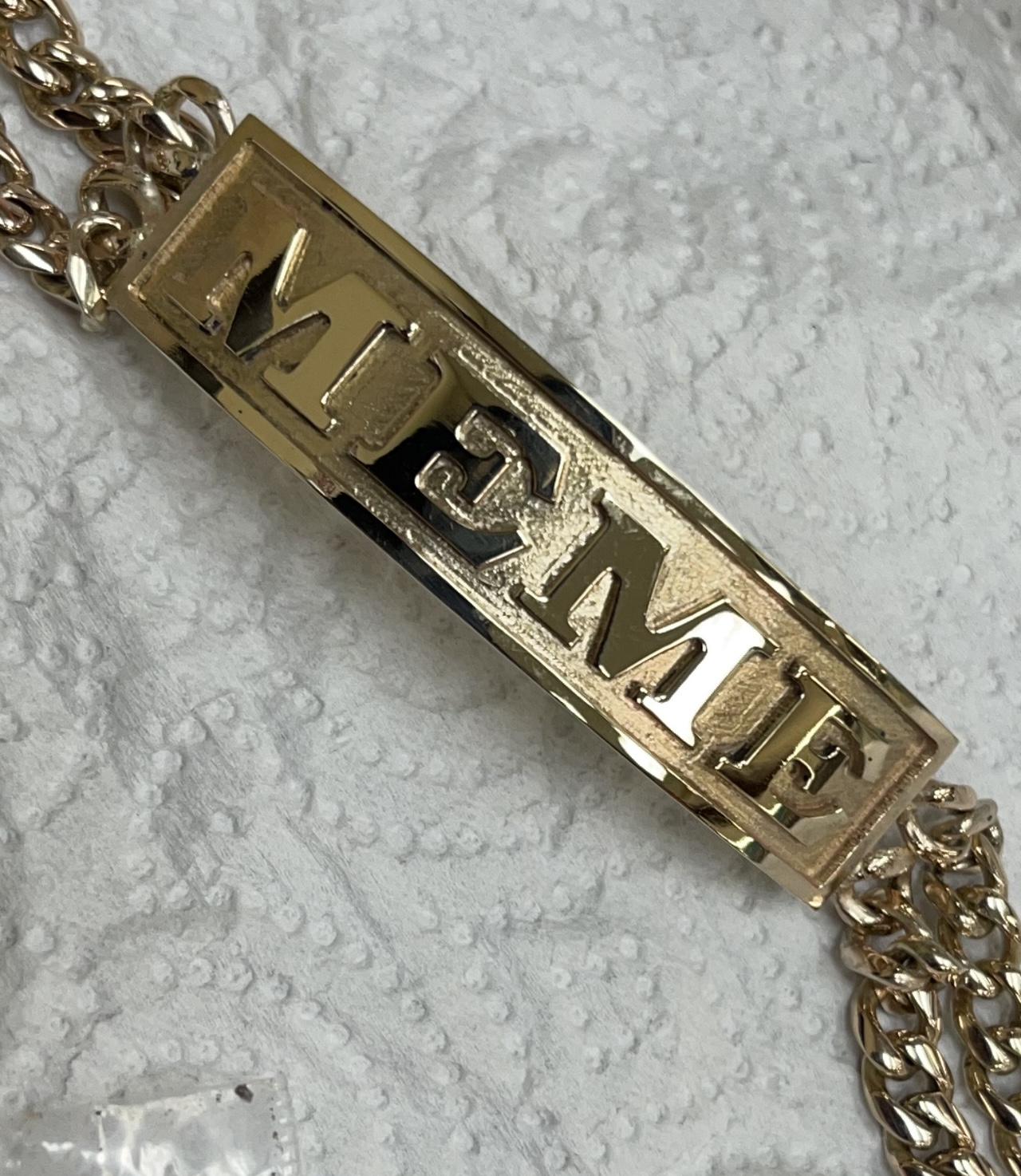
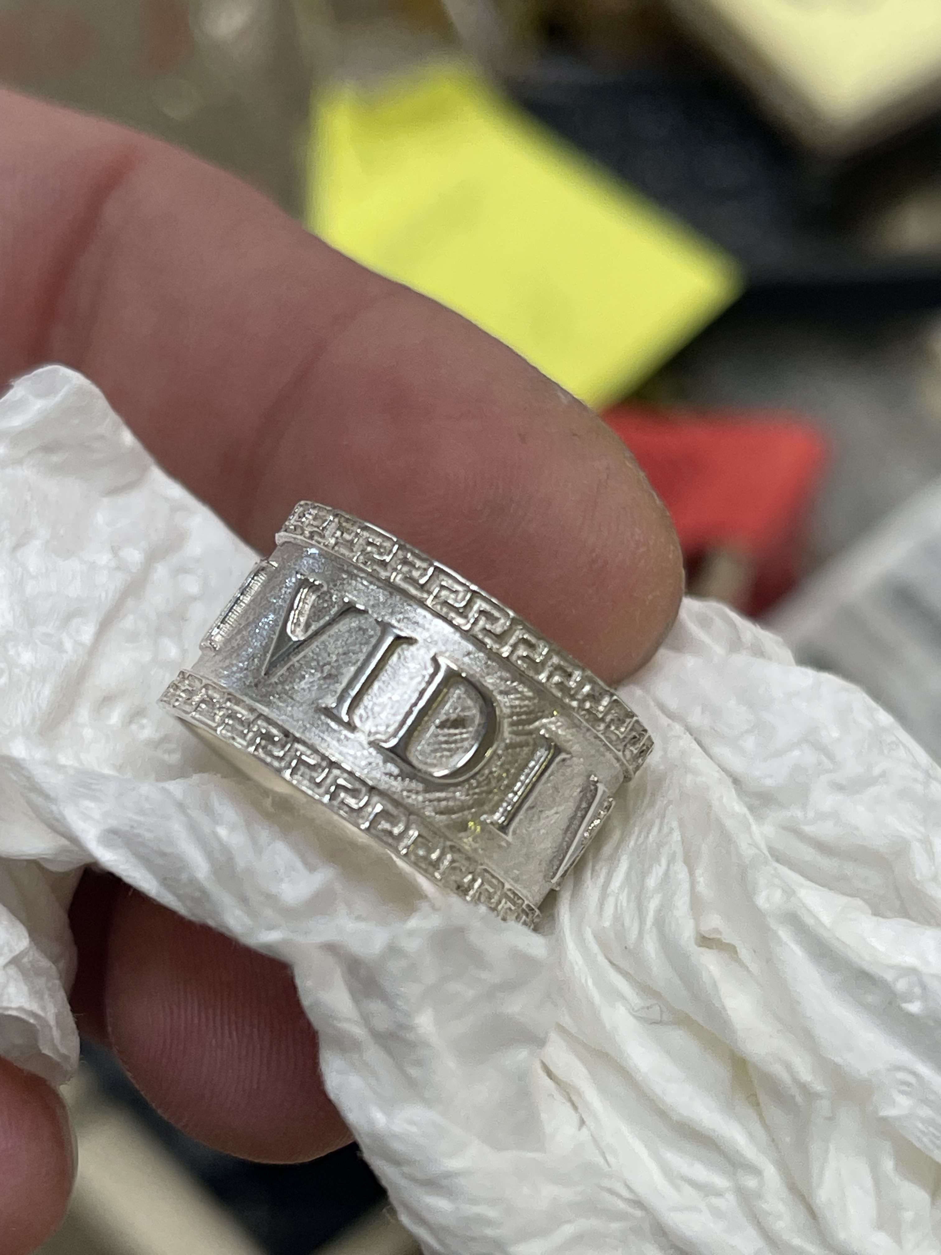
I’ve been doing this names in gold and silver with the 122 bit along with the carbide create software, my question is I am adding the same tool to fusion 360 dimentions and all and looks like there is some places where the bit can’t reach some places maybe I am doing something wrong.
3 Likes
Check the tool in the library in Fusion. Confirm the length under the collect.
The #122 is 1.5 OAL . The VFD collect is 5/8" full engagement.
The length under the holder should be 7/8" ( 0.875) in the Fusion Tool library.
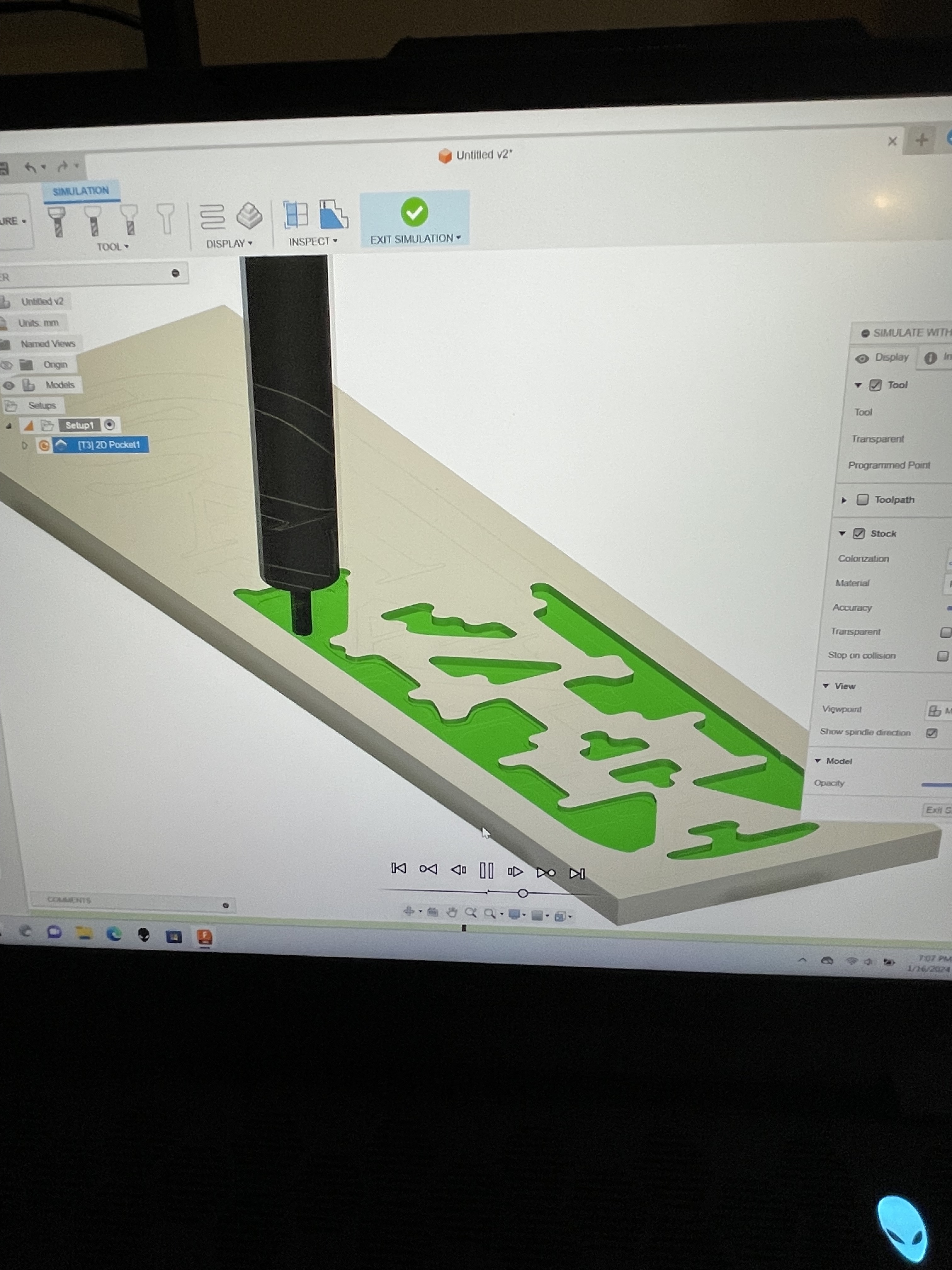
Are you getting a crash in Fusion simulation or just not contacting the part when running ?
1 Like
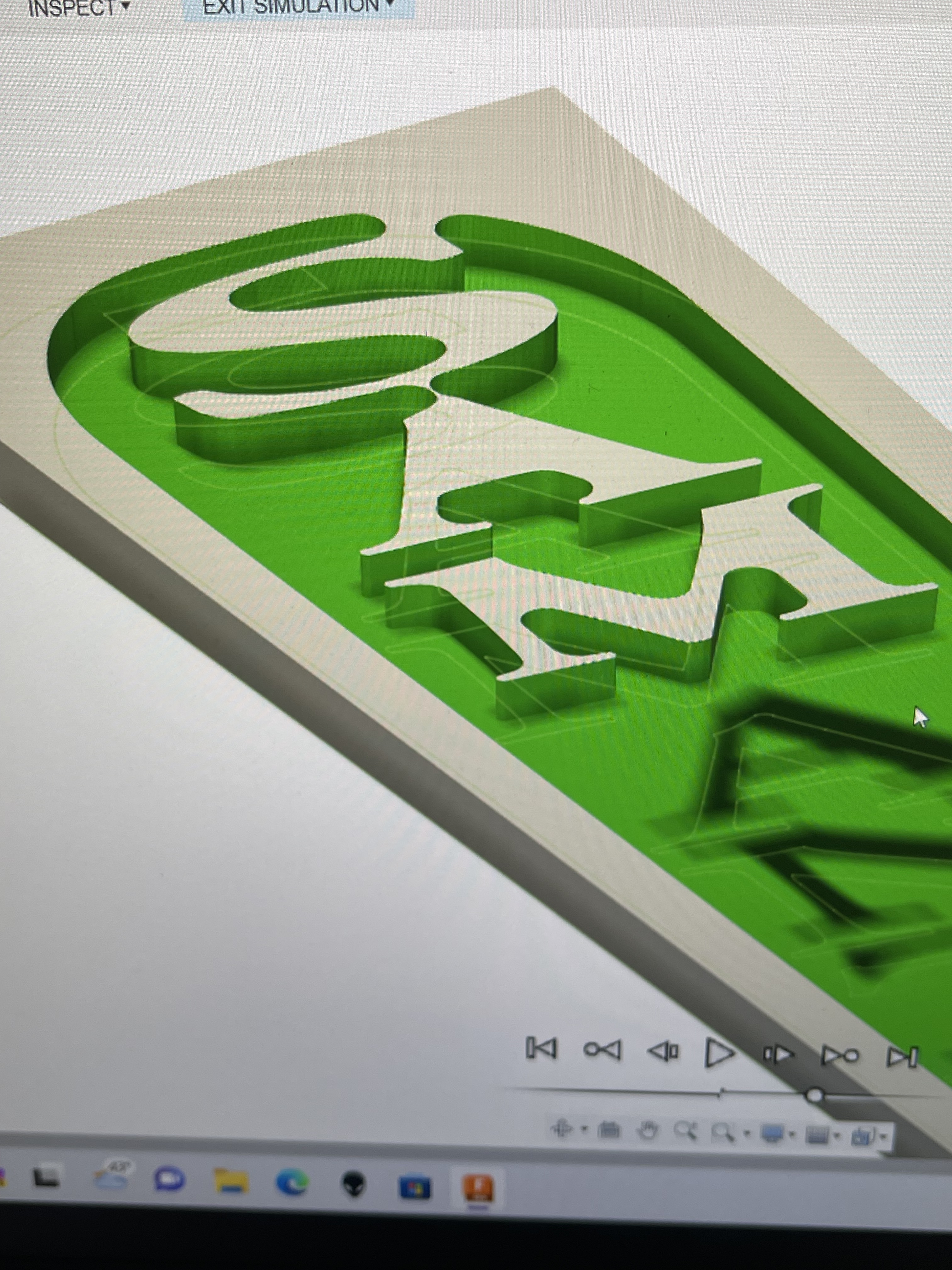
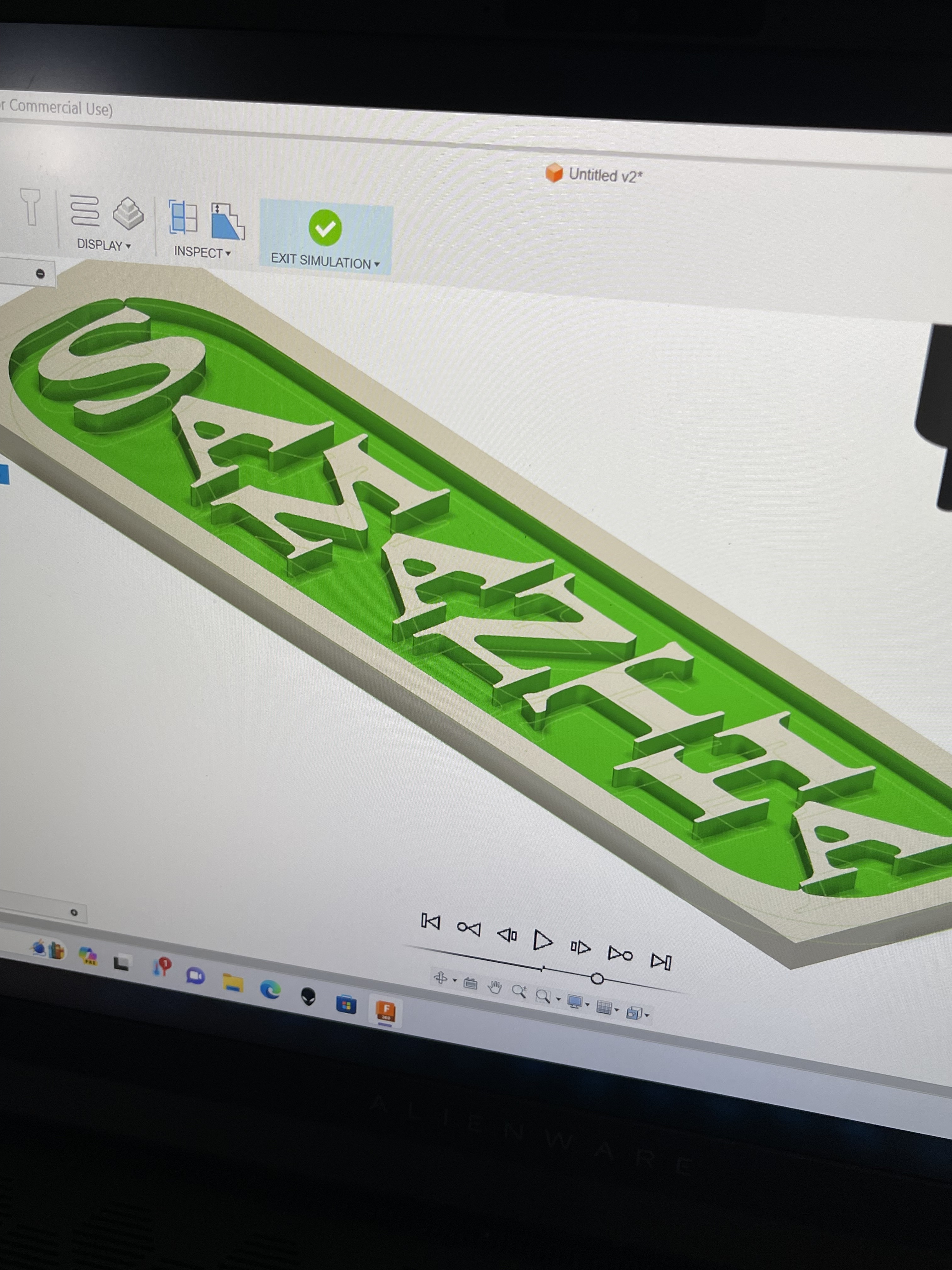
On the simulation letters are incomplete
I would look at …
The Stock versus the part to confirm alignment in the Setup
The Tool Heights in the Operation. You can look edge wise to confirm you are deep enough.
I am assuming the part face of interest is aligned to the XY plane in Design
1 Like
The Design sketch or solid looks like ?
Hopefully someone that has a clue will jump in
1 Like
Tool too large to fit in the small detail areas?
1 Like
How about …
I do not know what type of milling process you picked. I would guess 3DAdaptive .
In the Operation dialog, Select the Pass tab
There is a check box for Stock to leave and the value is 0.020 ( for inch models).
If it is selected, uncheck it. That way the tool will go to the feature geometry.
If you are using another milling operation, look for same option.
1 Like
Carbide create 7 is amazing and I’m still using it in my projects I just want to learn more and you guys are helping a lot thank you very much.!IMG_0386|375x500](upload://78roEH3qmdJp4yrMoFIlqwbluJK.jpeg)
This topic was automatically closed after 30 days. New replies are no longer allowed.