Been stumped the last day or so and decided I would come here for some help. Lo, I see someone posted about flip machining a guitar body! Still, I am deep enough into my design that I’m hoping to get some feedback on my process, rather than adapt to what I am seeing (and not quite understanding) from others.
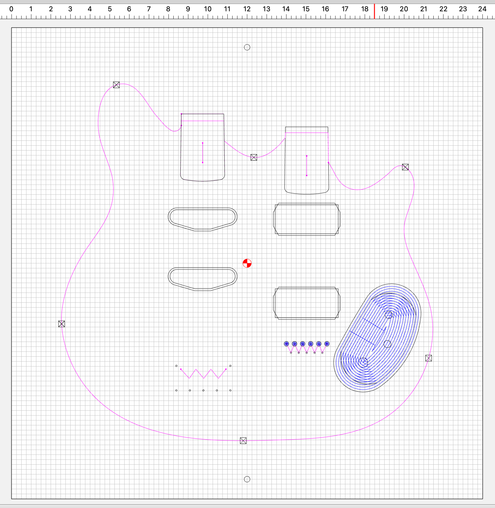
I have a pretty simple design with pockets and a countour. I set up the stock size to be 24" x 24".
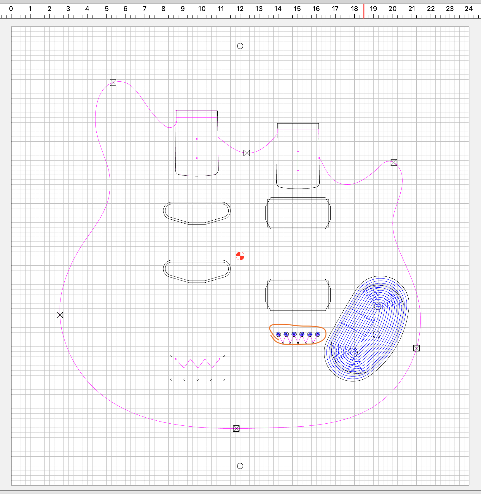
As you can see in the image, I created pockets for the top and bottom on the same design. I enable only tool paths for the top and cut those, including two index holes that are at exactly 12" in the x-direction, and also horizontally aligned with “toolpath zero”. Then I flip the piece over and use dowels to realign to the index holes in the wasteboard. I also flip the design, disable the top toolpaths and enable the bottom toolpaths. In the following screenshot I have circled in orange an area were the strings pass through the guitar body.
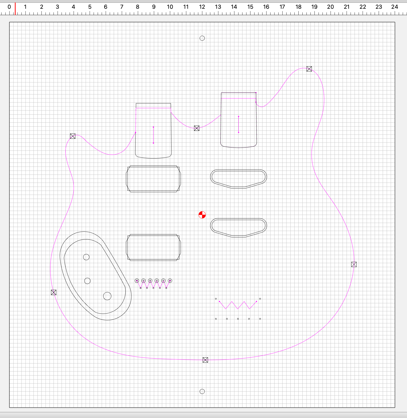
The top has toolpaths that make 1/16" holes about half the depth of the body. The bottom toolpaths make a 1/4" hole about half the depth of the body. Those holes do not meet in the middle. They seem to be about 1/8" off in the x-direction. In the design the holes definitely have the same x-distance between them and the “toolpath zero” whether flipped or not. Here is the flipped design before I export the bottom toolpaths.
I know there is a bit more trouble shooting I can do. For instance, if I leave the index hole paths on for the top and bottom, do they match up? But I though I would check with this group to see if there is somethign simple I am missing or a flaw in my logic.
I’ll attach the file itself as well.
For the record, the machine usually demonstrates very good accuracy. The top and bottom holes seems to have the same distance between them. I am using CC7 build 764.
Using center for the flip potentially doubles any error — my preference is to set up the file for Center-Left, then put one side in the top half (setting zero as if for Lower-Left), then rotate and probe the same corner (but now as if for Upper-Left).
Try it out on a piece of scrap w/ a square corner.
It can help accuracy to use the CNC to cut the stock edge which will be against the placement guides. Small variations in square & table/mitre saw cuts can easily throw out a double-sided operation. Also, test a flip design with scrap material before moving to good material.
If using edges for alignment, this is certainly true. But using dowels should eliminate that potential error. Assuming the flip in the design & on the machine are identical, it should be perfect. Unless the machine isn’t perfectly aligned. If the Z axis isn’t moving perfectly perpendicular to the table, the dowel holes won’t line up correctly.
This is what I was thinking. I guess my question is: am I doing the actual flipping things correctly? I made a 24"x24" vector and centered on the guitar and the index holes in it. Then flipped the guitar and index holes. The holes did not move (as expected). The distance the holes in question are from the “toolpath zero” in the z-direction is within .003". I am seeing the holes centers off by nearly 1/8".
I understand that there are many ways to do this but I’m not sure they all apply and I think there is value in figuring this out. I guess I will try flipping and recutting dowel holes to see how they line up.
So in the first setup you are drilling through the stock & into the wasteboard?
Then inserting dowels & flipping the stock & aligning the holes to the dowels?
This should work, and get you as close as you’re going to get. The only thing I can think of is if there was an error flipping the part in the design, or the Z axis is not moving perpendicular to the table.
To check it, put a long tool or dowel in the spindle and use something square to check all 4 sides of the tool. Adjust the tool so the top of the square & top of tool are lined up so you’re seeing the squareness over the greatest distance possible.
Now on all 4 sides with it lined up that way move the Z axis up until the end of the tool is at the top or above the square. If there is a gap, or if the tool pushes the square away, then the axis is not lined up.
No matter which method you use for flipping & alignment, ensuring the machine is cutting registration holes/edges precisely is key.
For making dowel holes, using a smaller endmill to run around inside the hole can give more accurate results than a larger endmill making small/limited movements which can end up being more of a lobed triangle vs a circle.