Has anyone used CC to kerf wood for bending?

Okay, we need to come up with 1–3 sets of toolpaths for each part:

  • 15 degree V carving for the lid relief cuts
  • 90 degree V carving for the bends for the balance of the non-flat parts
  • arbitrary/calculated V carving for the bend at the front/back
  • a profile cut to cut the parts out (which will probably need tabs)

and we need to express them in a way which will allow us to easily make toolpaths for them in Carbide Create or some similar tool.

The issue of course is that we can’t export an STL and get nice efficient V carving toolpaths (at least not w/ MeshCAM — is there some 3D CAD tool which would analyze the geometry and properly cut these out in an elegant (in the original sense of scientifically correct) fashion?)

So, we need to position 3D geometry at the surface in such a way as to get the necessary geometry out as 2D DXFs.

(I’ve asked that the RapCAD developer add export to Carbide Create’s JSON .c2d file as a feature, but doesn’t seem likely to be worked up — if someone could work up a way to create .c2d files using a flexible scripting language I’d be thrilled — at some point I’ll have to look into directly programming them I guess.)

Okay, there’s the BlockSCAD XML:

Box - plywood - kerfed - v3.zip (33.2 KB)

Next up will be exporting it to OpenSCAD and setting up the Customizer options and flattening things to make DXFs.

and the file is exported to OpenSCAD and set up for the Customizer:

2 Likes

Trying to wrap my mind around DXFs (since that’s the 2D export from OpenSCAD)— please confirm/refute my thoughts on this:

  • DXF is primarily a 2D data exchange format, but there is a 3D option for them which not many apps support (see discussion here: https://forum.solidworks.com/thread/56611 )
  • Some applications have a facility where a series of 2D drawings can be combined using a wizard into a 3D model (see discussion at: https://forum.solidworks.com/thread/56611 )
  • DXF (or SVG) import can result in a 2D view which is unable to readily allow creation of toolpaths directly (the lid design here being prima facie evidence) The usual solution here is to export an STL — but that won’t work for the design in question since I can’t find a CAM tool I’m willing to use which will put a V endmill all the way down into the groove

The only work-around I’m seeing here is multiple exports — the traditional top/front/side views aren’t supported by a wizard in Carbide Create or MeshCAM (does the latter support 3D DXFs? If so, how are they made?) The only workable export I’m seeing from OpenSCAD which would work with Carbide Create would be a succession of top views, one for each sort of cut which would then have to be stacked in register in a Carbide Create file and appropriate toolpaths (and/or 3D modeling in Pro mode) assigned.

Is there anything I’m missing or not understanding in the above? Is there some better solution (other than using Autodesk Fusion 360)?

2 Likes

Okay, working through the export. For most parts it’s pretty straight-forward. We add three variables:

Endmill_Diameter = 6.35;
cuttingwidth = ceil(Endmill_Diameter * 1.1);
tcw = cuttingwidth * 2;

and then wrap each exported part thus:

projection(){
    difference(){
        translate([-cuttingwidth, -cuttingwidth, 0]){cube([Box_Depth + tcw, bottomheight + tcw, 0.001], center=false);};
        translate([0, 0, -0.001]){makeside();};};};

which results in a part suited to exporting as a DXF:

Next up is doing that for each part.

2 Likes

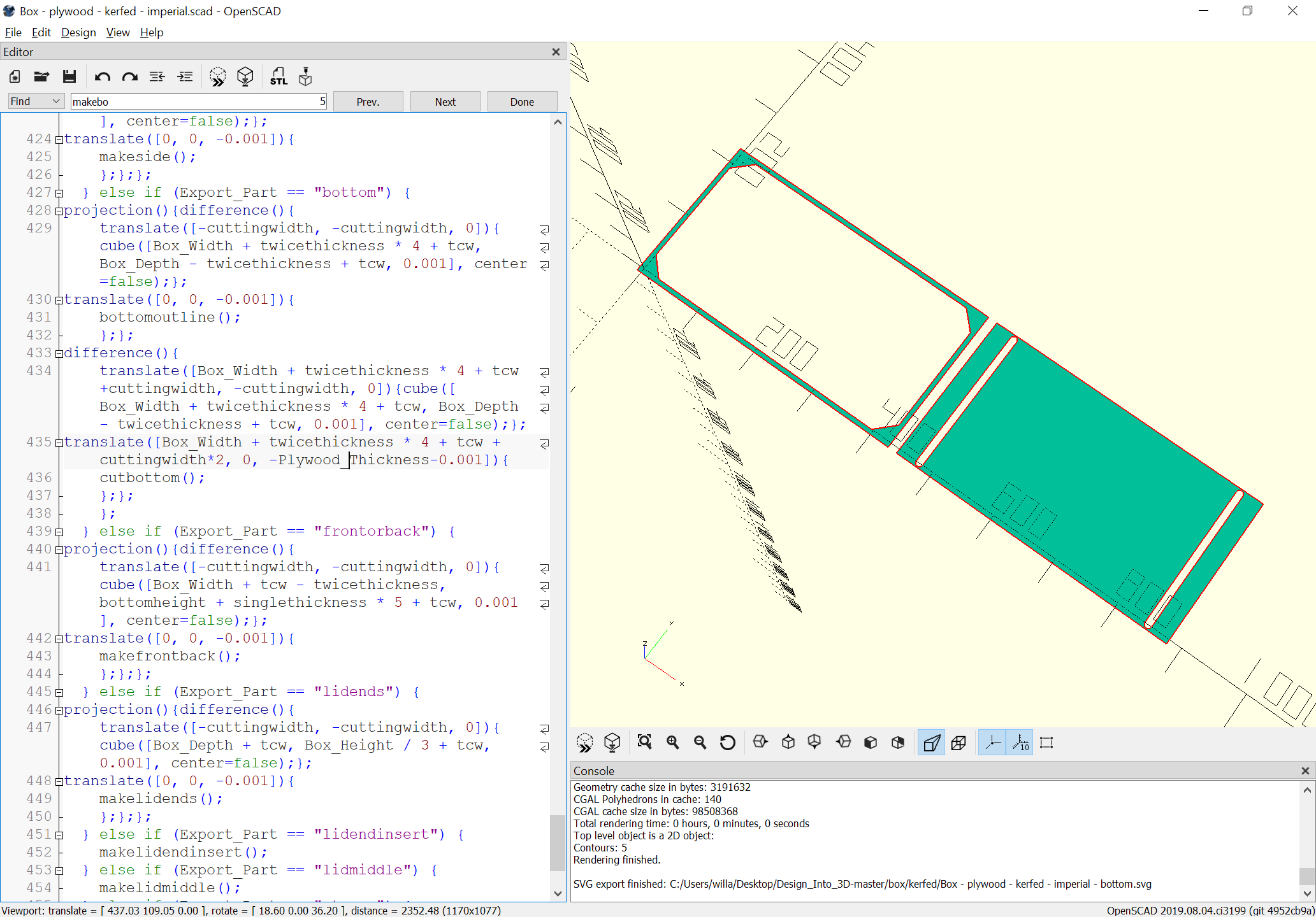
For parts which have V cuts the V cuts are output in addition to the actual part outline surrounded by a rectangle of the same size:

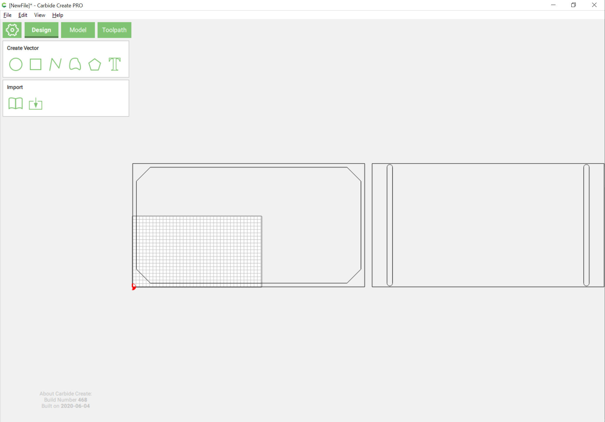
this allows them to be imported into Carbide Create:

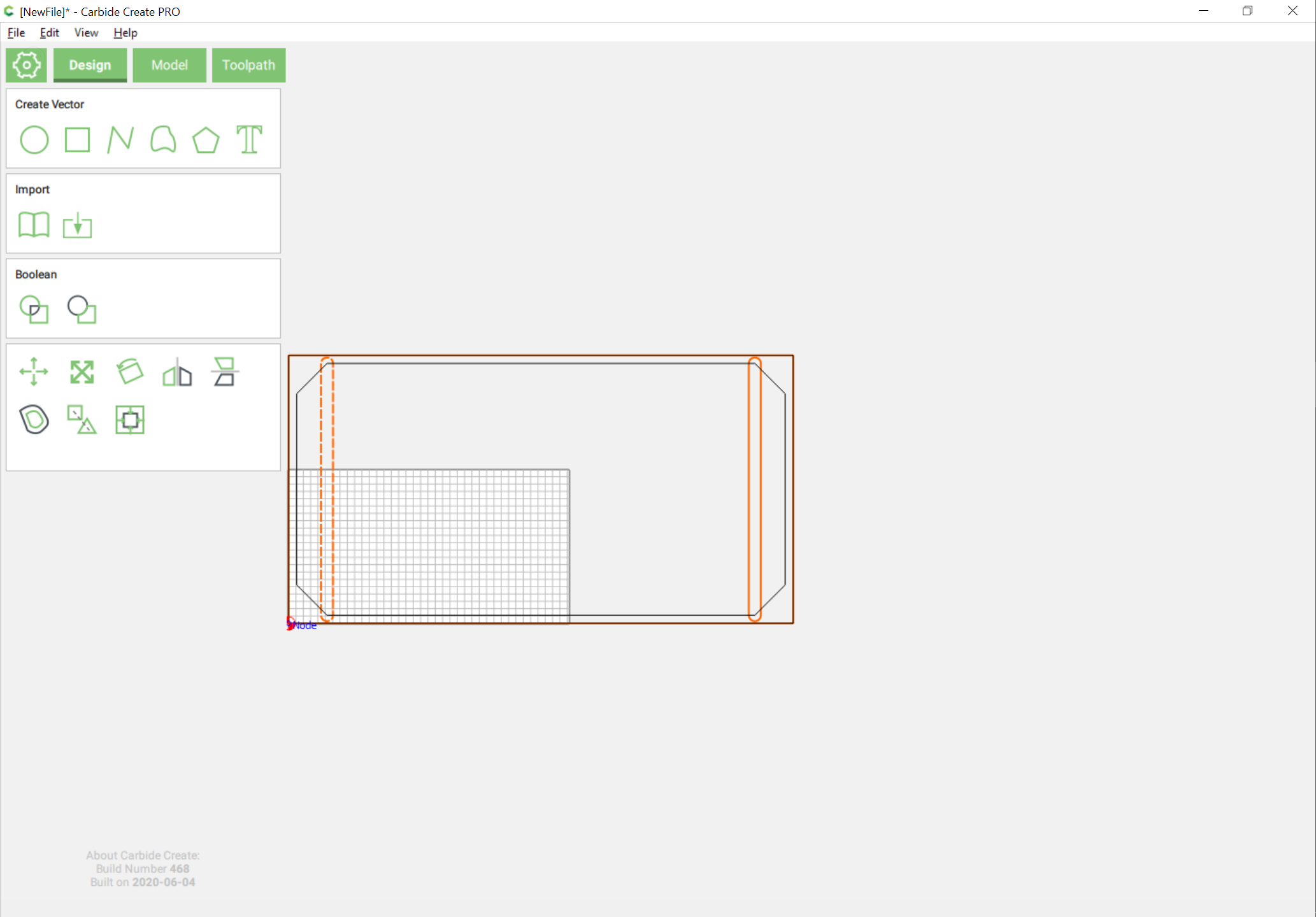
and the two cuts dragged into register:

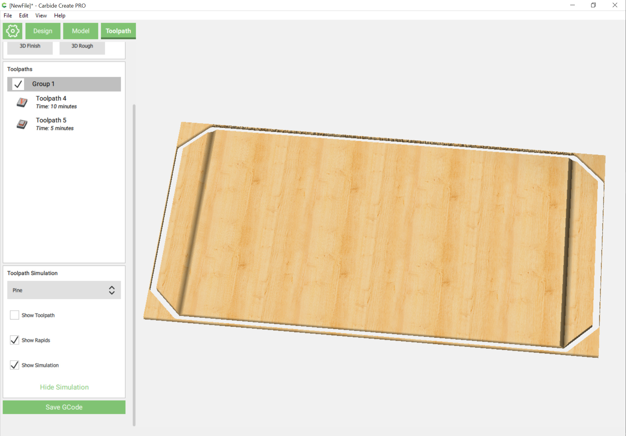
and appropriate toolpaths assigned:

2 Likes

Import all of the parts into a file and arrange them so that they can be cut out:

then begin assigning toolpaths.

2 Likes

For elements which do not match an available endmill use 3D modeling rather than an endmill for a V carving:

1 Like

This then allows cutting the arbitrary angle:

along with the kerfs as an Advanced V carve:

Add toolpaths to cut out the perimeter and leave tabs:

1 Like

Well, got the first cuts done:

Next up is cutting the parts free and seeing how things bend.

4 Likes

Part removal was easier than expected, and bending worked well for the top curve. The 90 degree bend seemed to work well, but not as much success with the sharper bend on the top strap — 3D modeling that didn’t work as well as expected, will have to check the settings.

3 Likes

The 90 degree is likely just too much stretching for the fibers in the remaining layer. You’ll need a lot more of a smaller kerf, to make the bend distribute the tension along the remaining layer.

2 Likes

Agreed. I think I’ll skip the 3D modeling and instead just do a series of 30 degree V carvings. Modern adhesives would probably make it work, but I want something stronger and with less post-processing.

This is a venerable woodworking technique, and came across this fascinating article:

https://donsmaps.com/bentwoodchests.html

3 Likes

First try at the 90 degree bend with just as many 15 degree V grooves didn’t quite make the bend:

adding more and cutting again — will probably go to vertical front/back and change the bottom to have flaps on all sides and flip it over

3 Likes

Rather than iterate with large chunks of plywood which would then have to be repurposed, have decided to do what I ought to have done to begin with: a series of systematic test cuts.

Since I have a Starrett protractor head which has a half-length of 2", will use 4" sections.

The successful bend above used 0.0082" in-between each kerf:

so we’ll make a series of parts thusly, labeling each as to the number of grooves, then glue them up and measure them.

3 Likes

So, we make a test file:

Next up is toolpaths, then cutting, then cleaning everything up and glueup, then measurement.

4 Likes

I guess I’m just too busy with my own projects to even think about testing that way. :smiley: Will, you must be possessed! :smiley: +1

2 Likes

Made a file for making test files:

https://www.blockscad3d.com/community/projects/961603

Next up is exporting that to OpenSCAD, hooking up the customization, and adding the command to flatten out the DXF export option so one can actually export a DXF — then I can try cutting a file again.

4 Likes

Updated to make two different sorts of test cuts (Number or Spacing):

https://www.blockscad3d.com/community/projects/961603

1 Like