I was about to start a bombay chest project that requires bent sides. I was planning to use the technique of kerfing wood on one side, to allow solid wood to be bent, but it’s a technique that requires a jig of sorts and a lot of monotonous, tedious, cutting. Seems like it would be a simple CNC technique to route the grooves to the perfect depth and spacing.
Has anyone done this before? Any advice? Tips for generating lots of recurring parallel lines?
I’ve not used CNC cuts for kerf bending yet, be interested to see how you get on.
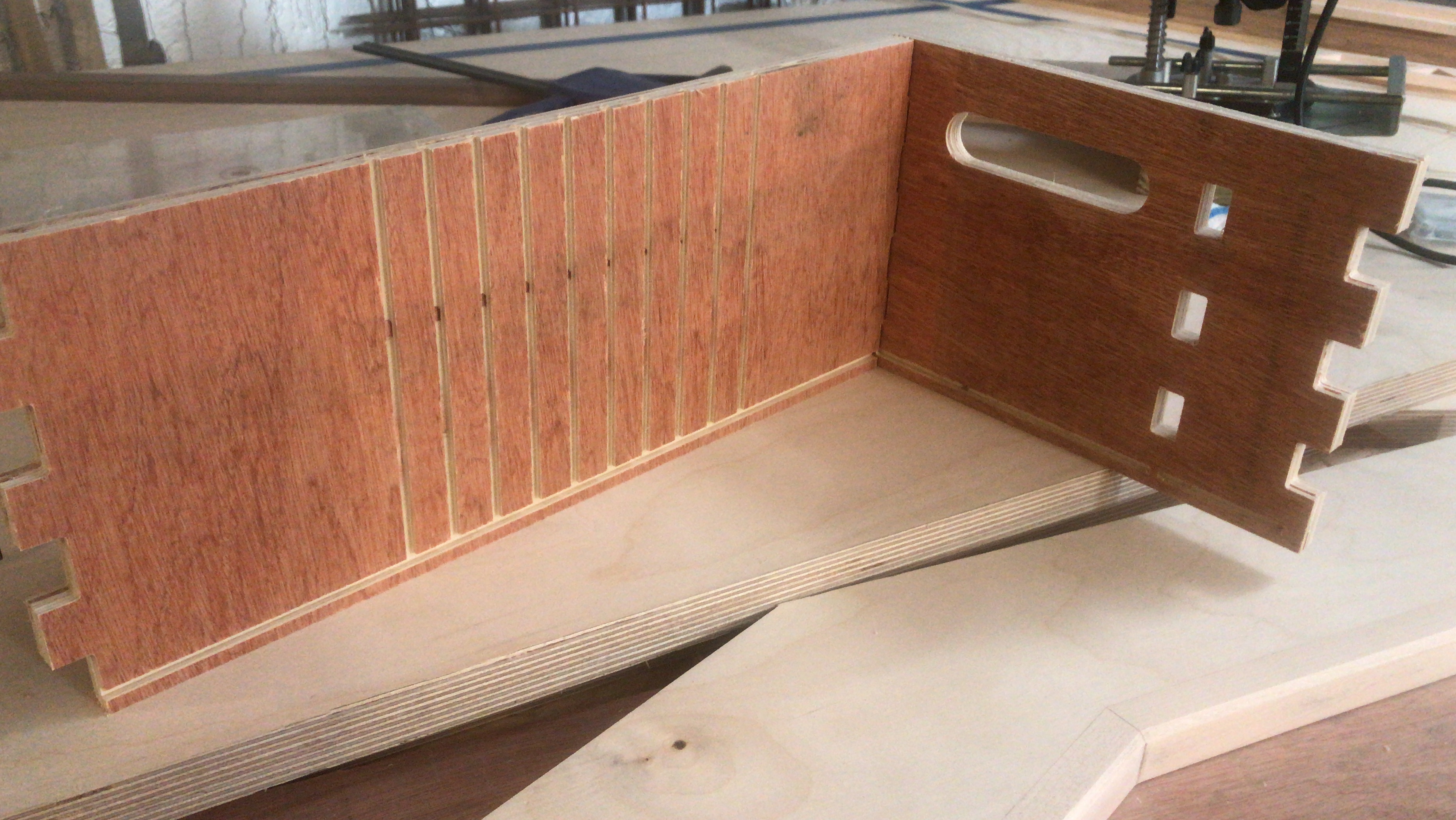
I have used the CNC for repetetive cuts, in this case for vertical slide in dividers that I could move around to adjust partitions in the box.
This was in Fusion so it was just a rectangular pattern on a specified interval, not sure about Carbide Create, sorry.
In this cheap ply I ran a contour cut through the middle at 3mm stepdown with 0.5mm stock to leave each side of the channel on the Carbide 1/8th flat end bit and then came back for a finishing pass with the same bit to clean up the sides.
It might be worth trying one of the steep angled (pointy) V bits for a kerf cut so that the cut tends to close up as you bend the wood rather than leaving a large open gap at the bottom? Esp if you were planning to calculate the amount of material to remove based on the difference in circumference inside and outside and then glue up the closed gaps…
I’ve been looking into this sort of thing for metalwork:
Wood should be easier — it’s unfortunate that V endmills aren’t available in arbitrary angles which would make it a simple matter of calculating the exterior circumference of the bend, the interior, then determining the chords which would need to be regularly removed to make the two distances meet when bent.
If one is willing to accept voids (fill with glue?) then of course one could just use a series of pockets.
Usually, it depends on whether you’re wrapping this around a form or not. For the chest, it needs to stand on it’s own…so the gaps need to be sized to close. That said, I have a variety of v sizes, from 90s to 15s, so it’s possible that I can manipulate something close enough to close. We’ll see. But to bend around a form, straight pockets would suffice.
I’m a LightBurn user, which has a “Grid” tool. It’s easy enough to set up the kerfs in LightBurn, save it as an SVG and import it into CC to apply the ToolPaths. The good news is that sizing when moving between the two systems will no longer be an issue!
Use an 1/8th bit, that is the same size as the width of a table saw blade. Make your cuts and bend around your form. On the CNC you just need to know your spacing for the cuts.
Another way to do it is get bendy plywood and veneer and just wrap around your form . A vacuum bag would work best for this, but a form and lots of clamps will also work.
@OldDude That’s a very nice calculator - even has an Imperial version! You can see that how, once that calculator does the measurement, laying it out on a CNC would simplify getting precision into the process.
Most of my bending projects are done with bent-lamination techniques, but for wide boards, like the sides of a Bombay chest, the kerfing technique is better suited.
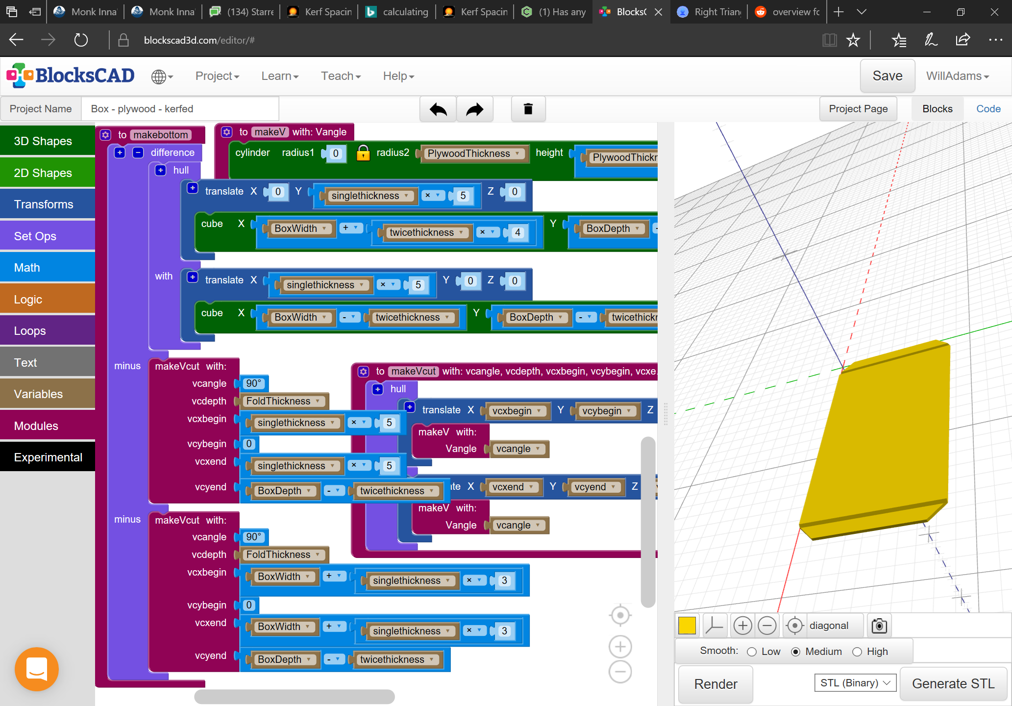
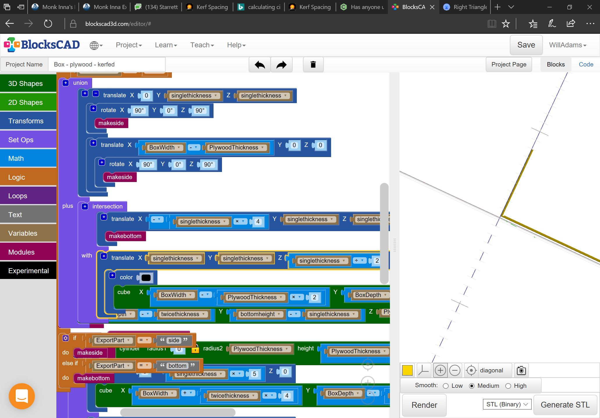
Like most things I suspect it’s a balancing act — I suspect it’ll be necessary to have more grooves — will put some code together this evening — I’ve got a project this would be perfect for, and for once am already stocked on suitable material, and should have the correct endmills, so no excuse for not doing it.
I think, for the majority of cases, using a VBit is not going to get you what you want. I assume that your thought in using it is to try to get more contact area when the gap closes upon bending. The issue will be, that that gap will only close if the V Bit is the precise angle needed to get the desired arc. In the vast majority of cases, that angle will not be 15, 30, 60, 90. So, unless you have some custom bits made, or your arc is perfect for one of those angles, you’re not going to get the closure you’re looking for.