@WillAdams William, I’m trying to figure out what you’re doing here…it looks like you’re trying to build the whole box at once, with all of the kerfs applied to both sides of the box. In practical terms, you won’t really want that to be the solution, because the size of the piece will easily outsize the capacity of your CNC in most actual applications. You might want to consider one bend at a time, determine the geometry (spacing, angles, depth) to close the gaps when you bend a particular angle, and determine how to position the workpiece to apply the bend wherever you intend. That will simplify your design and provide a reusable solution that anyone can apply to any bend.
As I said, I’ve done the technique using the tablesaw and tableslaw sled on multiple occasions, using a calculator as a starting point and then a brute-force, trial-and-error approach to hone the solution. Being able to do that in a model would simplify layout, but the real save is in the positioning and precision of the kerfs themselves. That’s where the CNC is going to actually save us time.
Yeah, I lost my “Quark XPress user’s twitch” for Command s when I switched over to InDesign.
In this case it’s actually a bit more complex — I didn’t save the file locally, but had saved it into “the cloud”, but didn’t close the tab — apparently if the tab is left open and automatically re-opened after a reboot/reload one will sometimes get an earlier version which will then overwrite the latest saved version.
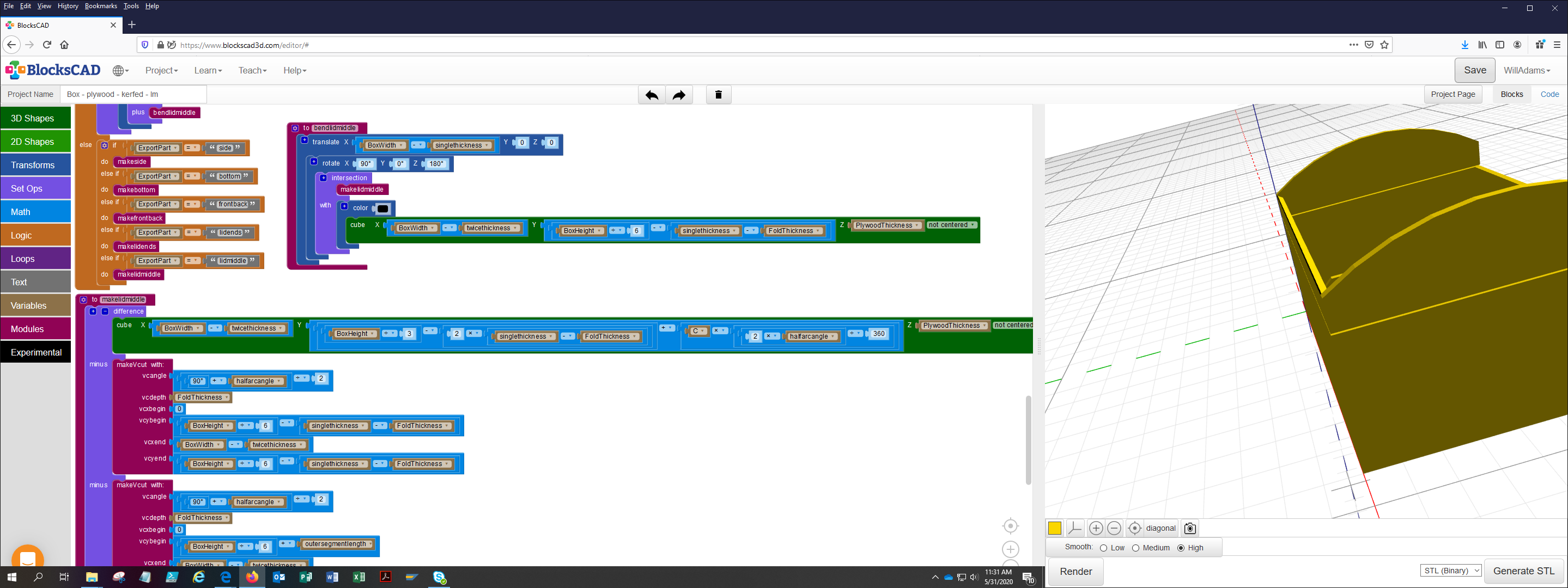
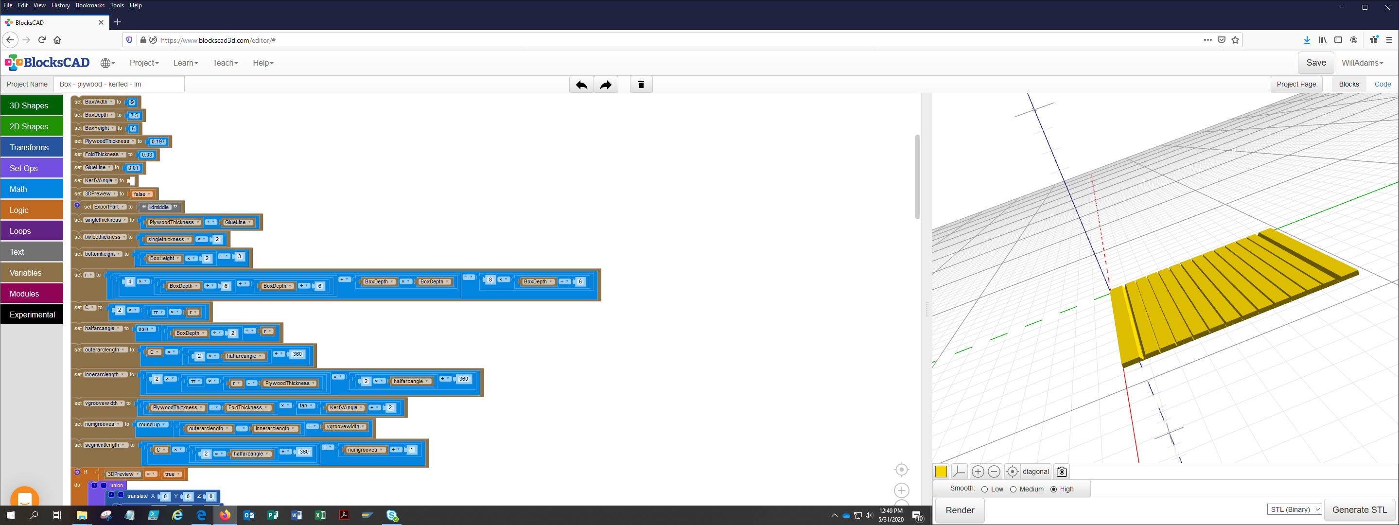
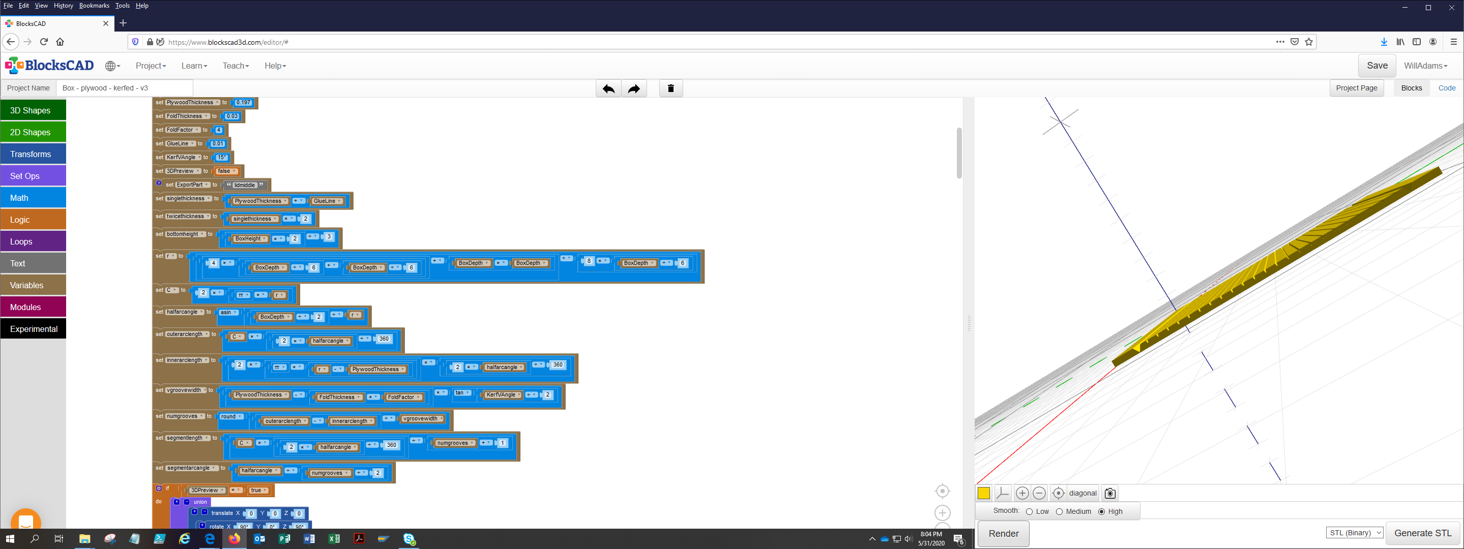
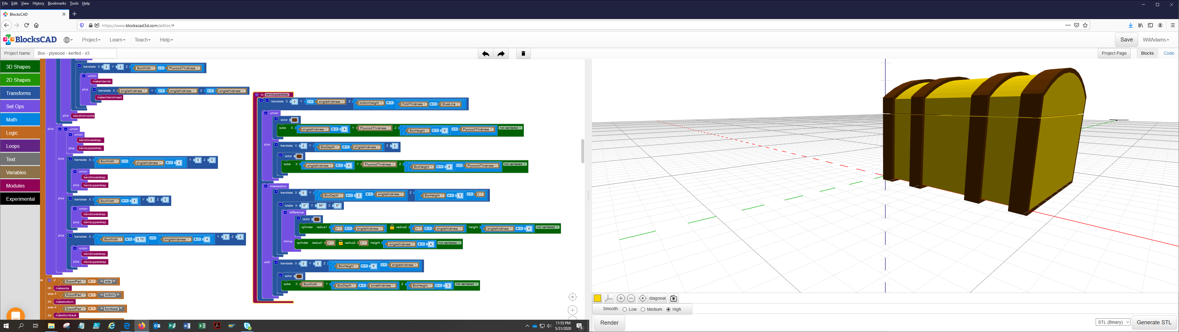
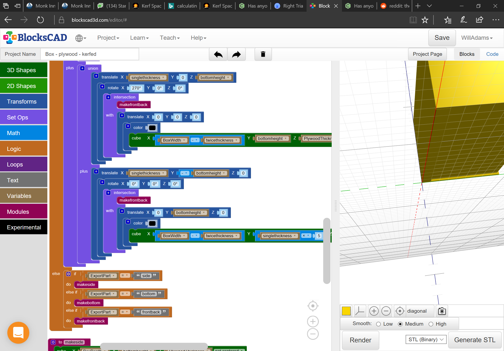
Anyway, we’re past where we were (finally) and are beginning to bend things for the lid (finally — to defend the topicalness of what has gone before, all the previous parts save for the sides and lid ends have bends in them):
so it should just be a matter of subtracting one from the other, calculating how wide the endmill will cut at folddepth, then distributing a series of V cuts across the width of the lidmiddle.
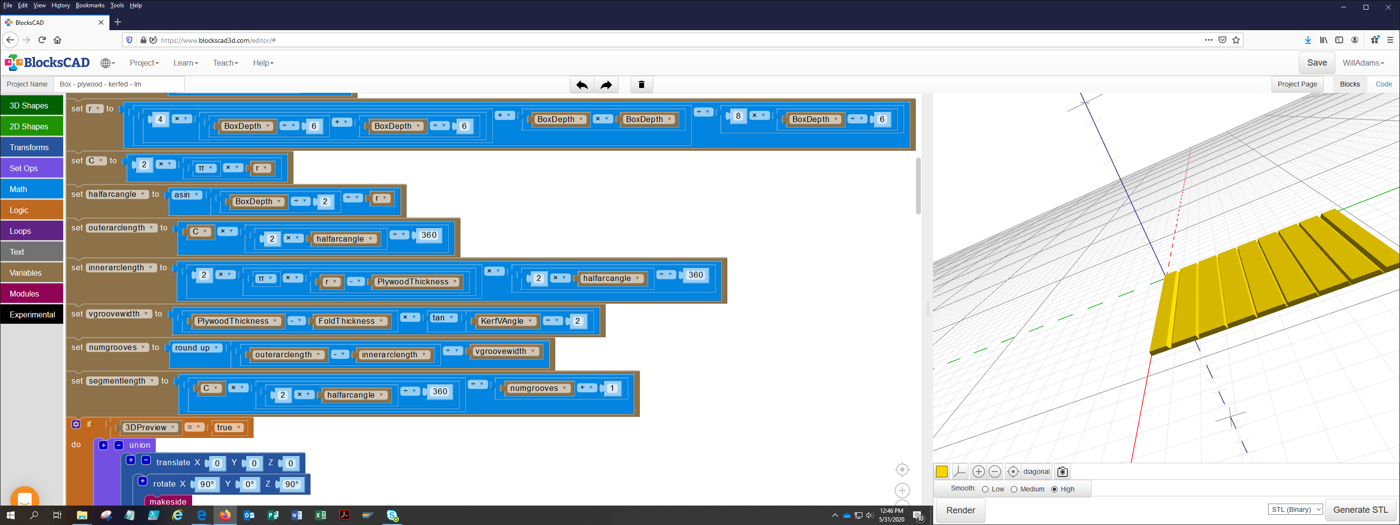
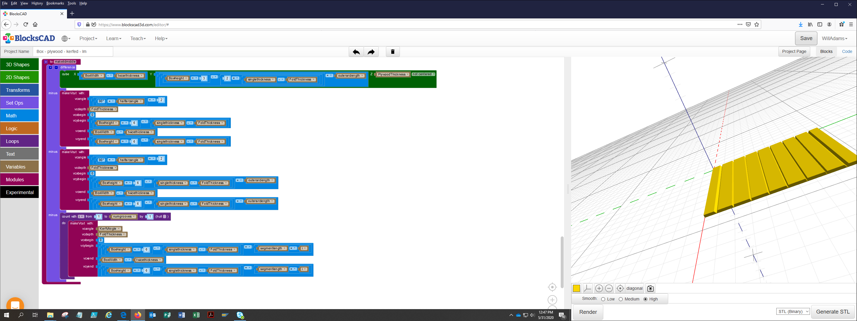
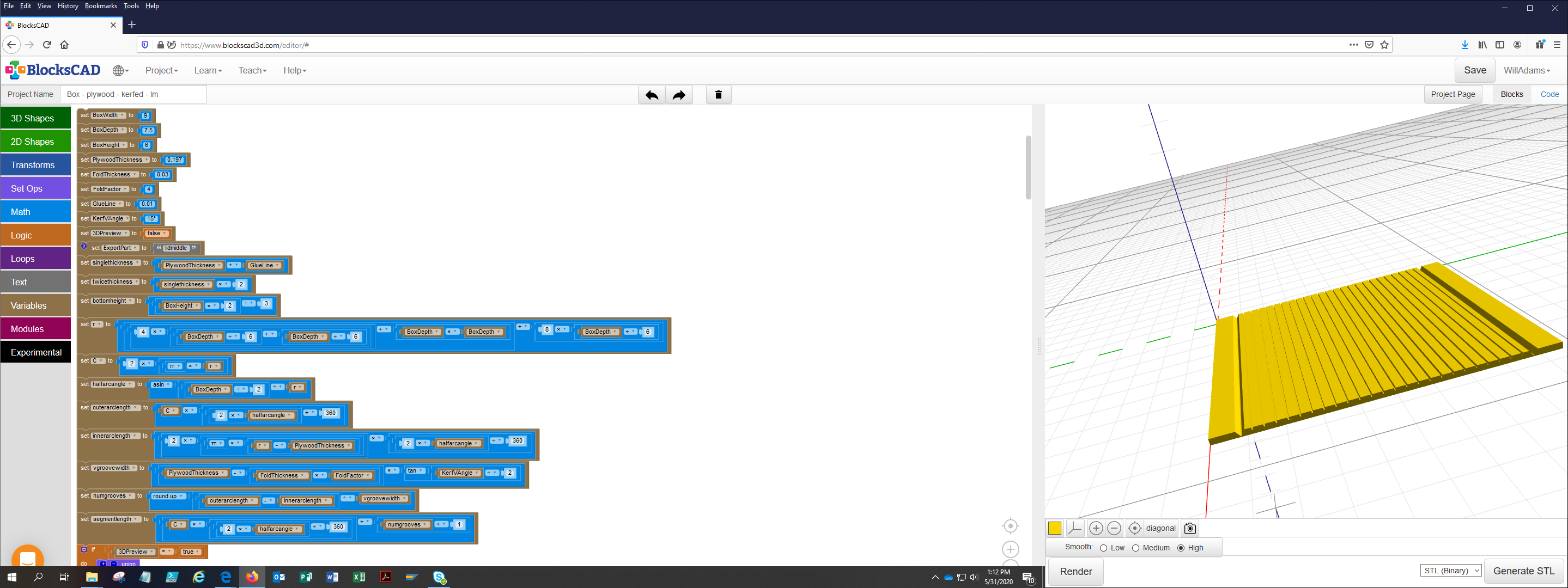
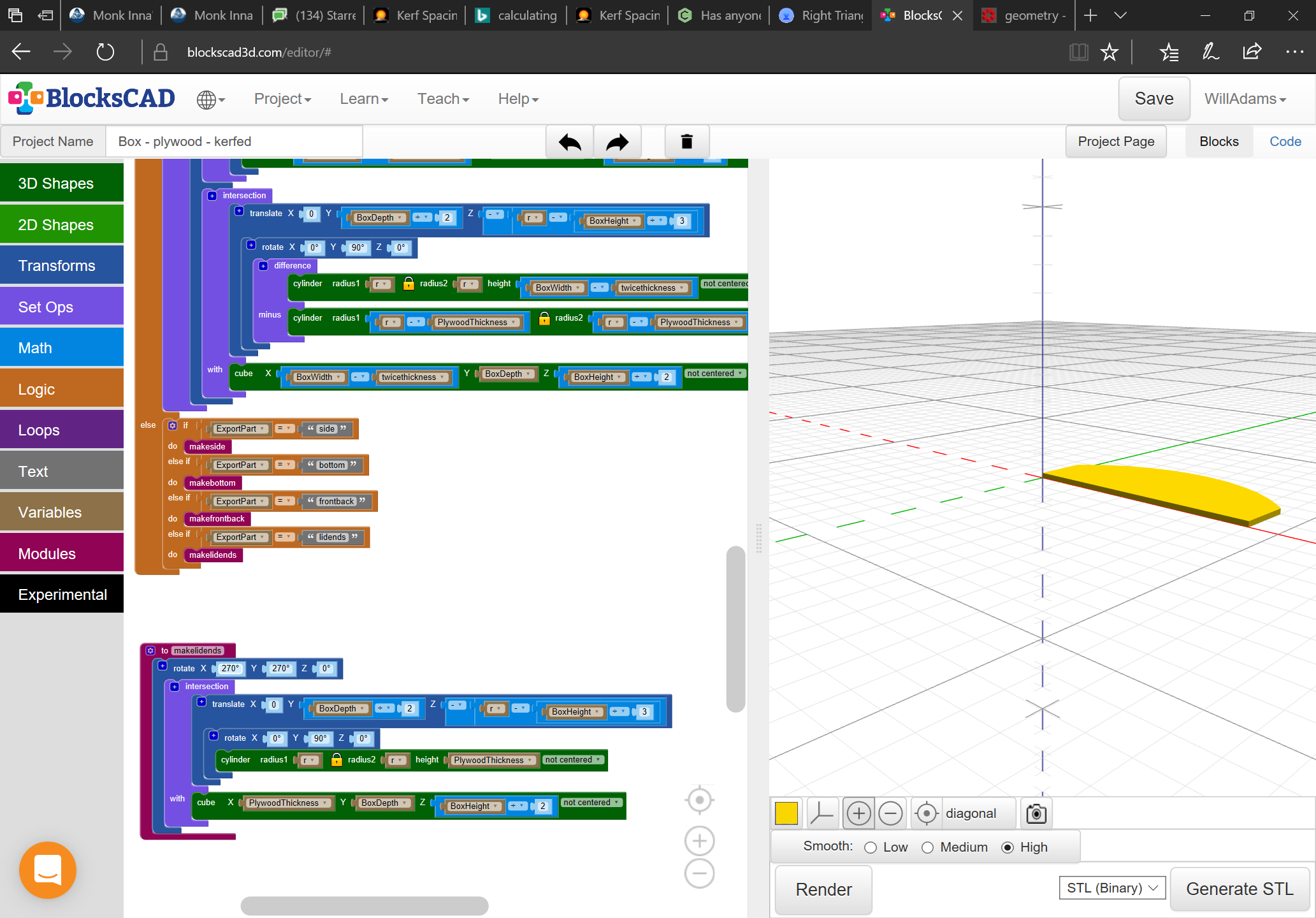
which seems correct — the assumption is that the rounding up will function to make the bending easier — I suspect though that we’ll want to use a more acute endmill than the 30 degree one I was planning. At 15 degrees we instead get:
which looks a little more workable, but still isn’t as many cuts as I was expecting.Probably adjusting folddepth and doing some experimental cuts will be necessary.
You could slot the lid into the side supports like a tambour…not unlike the way I’m doing it for the Bombay chest.
Can you show a cross-section of the bent sections to show how much the gaps are closing when bent? Is there a way to determine the formula for arc vs. angle on the gaps?
My probably crude idea was to cut the kerfs with a straight bit, fill the slots with Bondo or similar, make the bend and scrape off the excess Bondo before it hardened, so the inner surface was relatively smooth. I never got to try it though.
Can’t wait to see the results! So do you have a formula for kerf angle, depth and spacing, given a desired arc, distance, and height?
As for filling the gaps…in the traditional straight kerf design, the important part is that the two open corners of the kerf closes. What happens in the rest of the gap is less important, because, if the kerfs all close, the pressure of key-force is distributed throughout the panel and it won’t collapse under load. The area of the gaps, assuming the kerfs close at the open ends, is irrelevant for practical purposes.
My original question was intended to find a way to not have to repetitively move, register, and cut the kerfs — my plan was for straight kerfs (the traditional way). @WillAdams took that to a whole different level…there’s nothing like a challenge. I’m not certain that the result will be substantially stronger than the traditional methods (or the masters would have used it regardless of technology)…but it’s an interesting exercise. Seems the technique will still be limited by the available V-geometry, in terms of the arc radii and therefore, height/length of the piece being cut. Seems to me, gaps will happen.
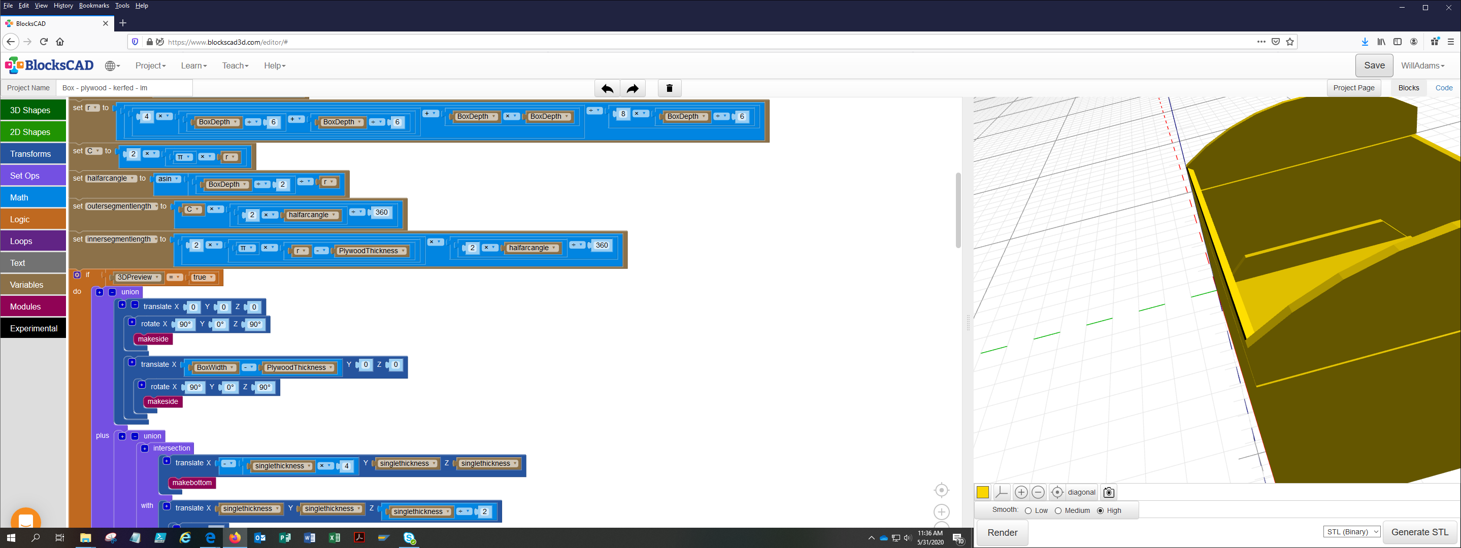
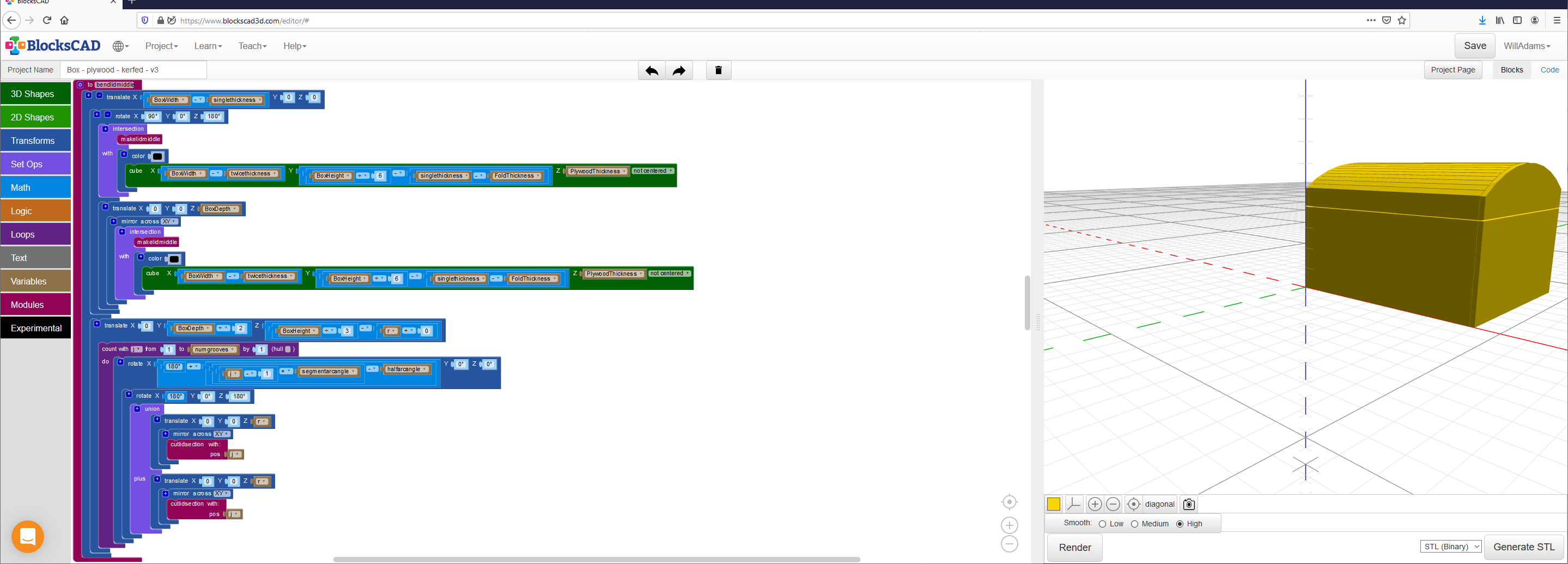
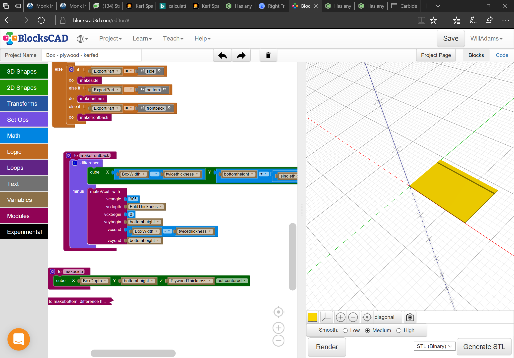
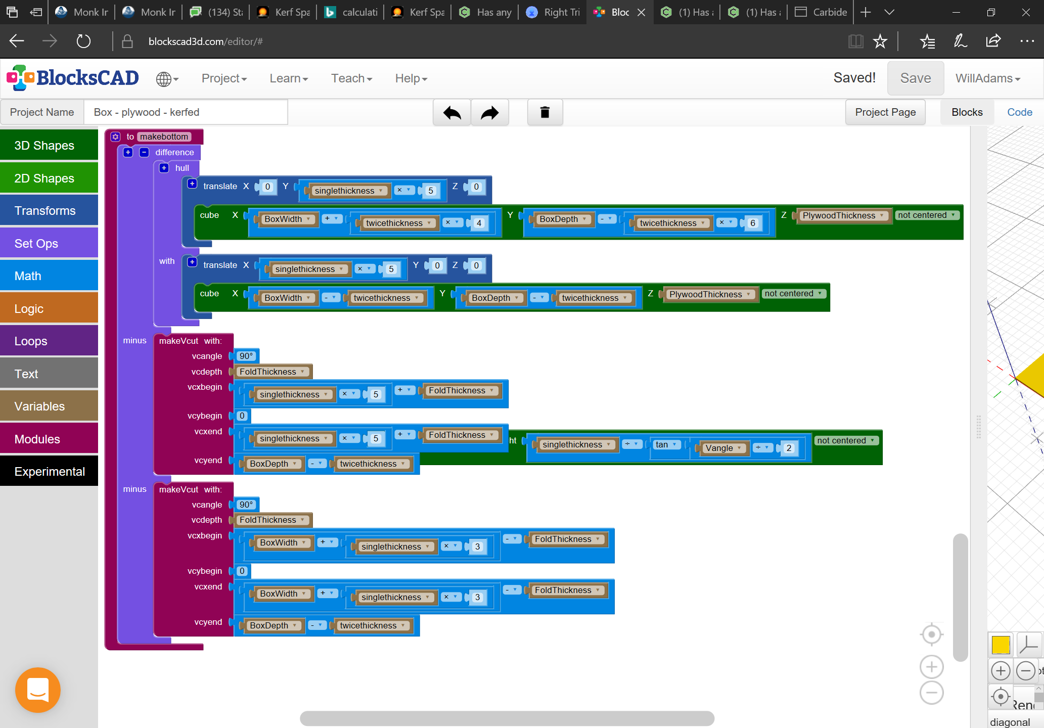
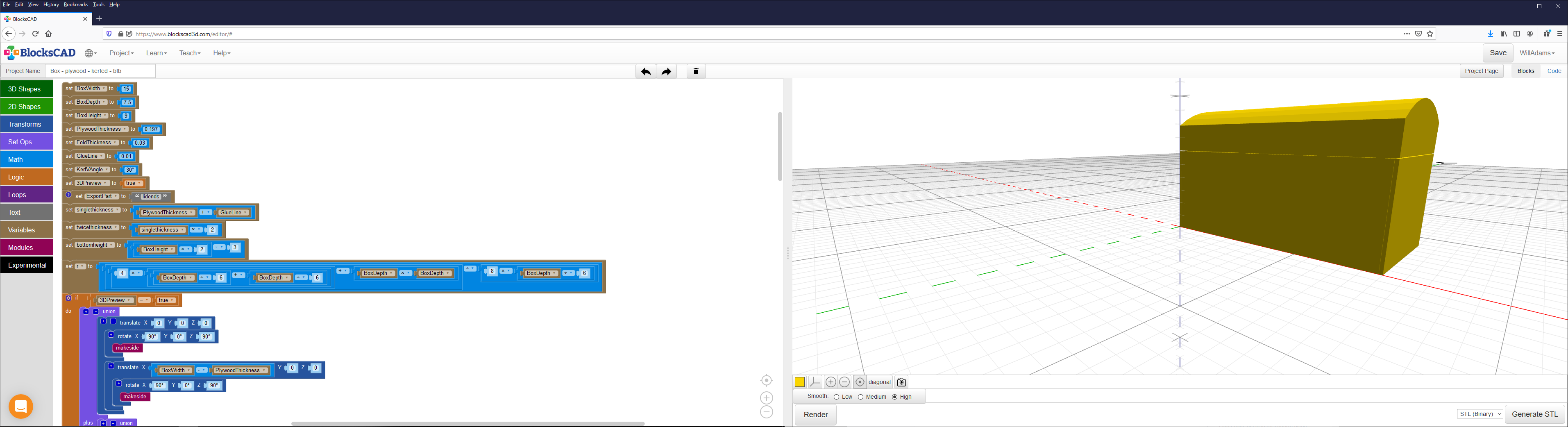
Yes, I put all the formulae in the screen grabs above. Let me know if you need any help with them.
I’ll be finalizing getting the parts out as DXFs next and I’ll load them as SVGs here, and will also be making the project on BlockSCAD public and putting the code up on Thingiverse so folks can use the Customizer there.
Isn’t the availability of horizontal cutting V endmills a fairly recent development? I’m not recalling a convenient way for folks to have done it before the router was developed as the first portable electric woodworking tool, and even then, the number of available angles would have been (and as you noted still is) limited.
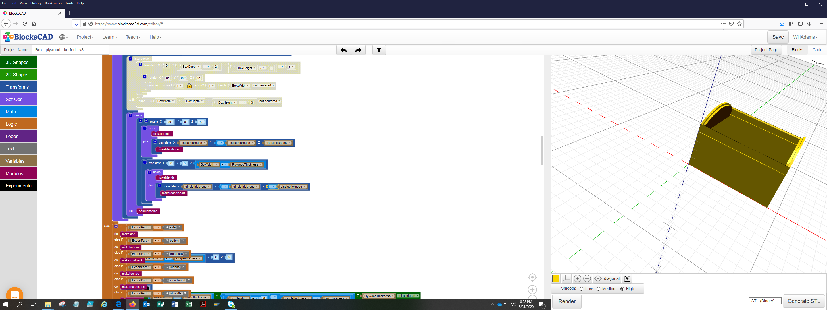
Okay, we need to come up with 1–3 sets of toolpaths for each part:
15 degree V carving for the lid relief cuts
90 degree V carving for the bends for the balance of the non-flat parts
arbitrary/calculated V carving for the bend at the front/back
a profile cut to cut the parts out (which will probably need tabs)
and we need to express them in a way which will allow us to easily make toolpaths for them in Carbide Create or some similar tool.
The issue of course is that we can’t export an STL and get nice efficient V carving toolpaths (at least not w/ MeshCAM — is there some 3D CAD tool which would analyze the geometry and properly cut these out in an elegant (in the original sense of scientifically correct) fashion?)
So, we need to position 3D geometry at the surface in such a way as to get the necessary geometry out as 2D DXFs.
(I’ve asked that the RapCAD developer add export to Carbide Create’s JSON .c2d file as a feature, but doesn’t seem likely to be worked up — if someone could work up a way to create .c2d files using a flexible scripting language I’d be thrilled — at some point I’ll have to look into directly programming them I guess.)
 Some old guy used to harp on his employees, “Save early; save often!”