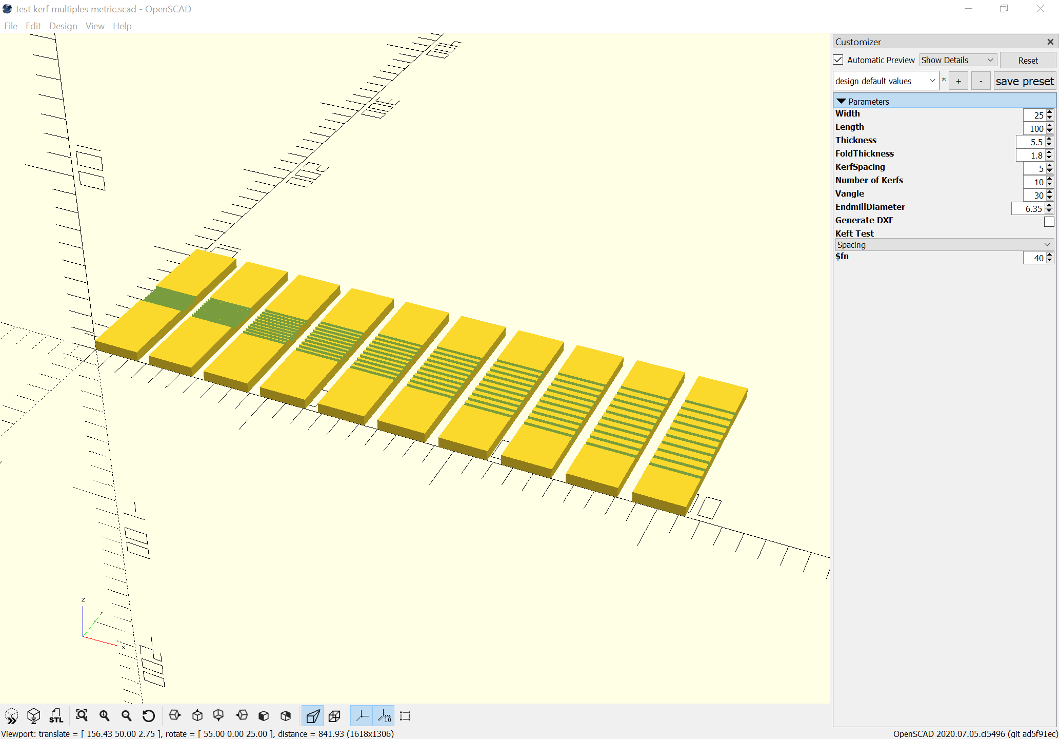
Need to adjust the code so that there isn’t zero spacing at the beginning:
1 Like
3 Likes
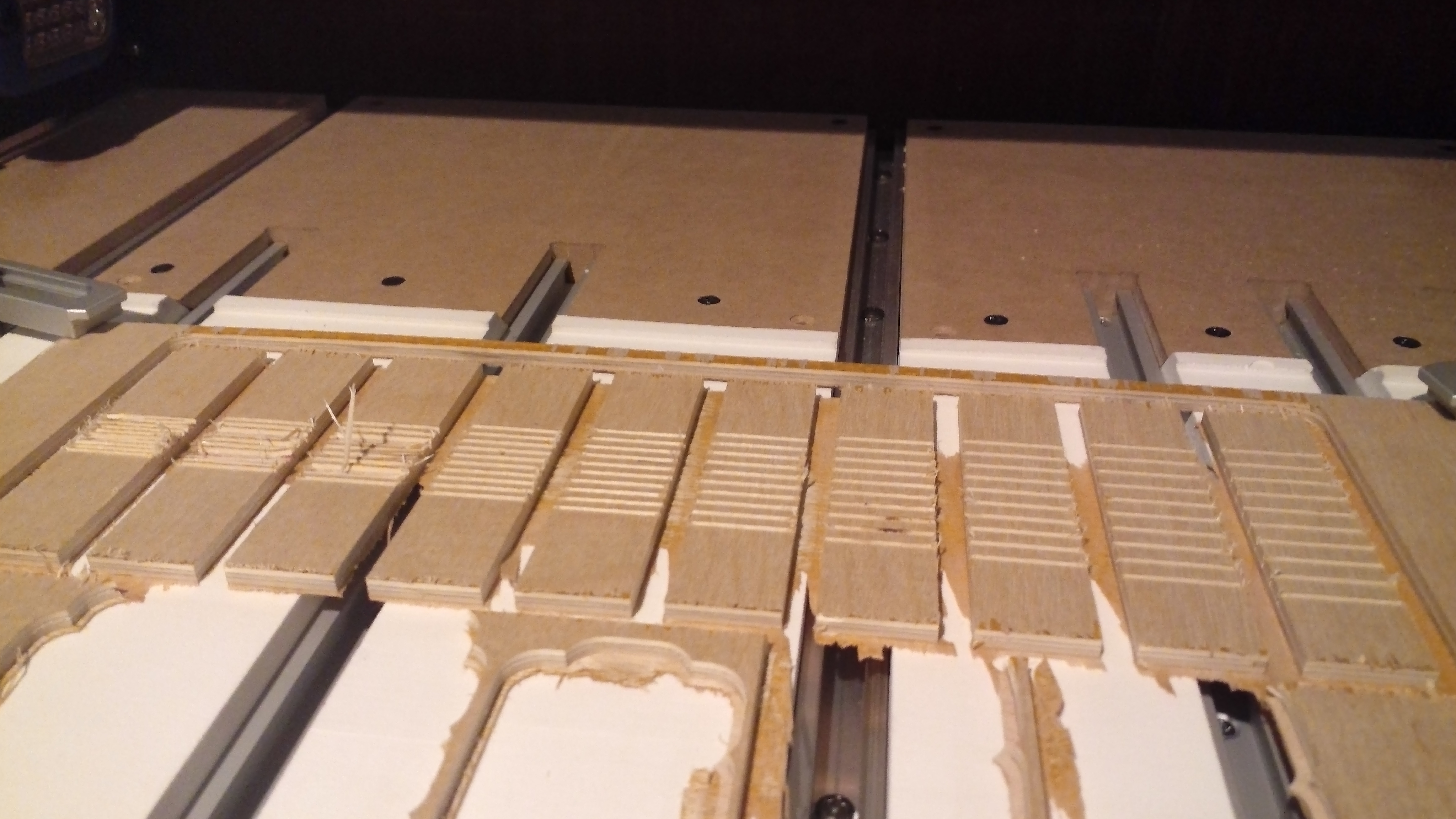
Cut out and prepped the parts and glued them (broke a couple), looks like 10 slots gets us a bit past 90 degrees pretty consistently.
The concern about the V cuts resulting in stress points is valid though.
Is what you’re getting to (after a lot of work and analysis) that the wisdom of the ages is holding true in the world of computers? Squared grooves, cut at the depth and spacing - according to the tried and tested formulas - is the best way to go?
I’m finding it’s valid, but I’ve also got a test piece which is about perfectly smooth in terms of its bend radius — it’s a full-sized on though, not the narrow 1 inch thing which are so delicate and had a very tight spacing which is quite sensitive to the orientation of the plys and which I haven’t been able to cut in a test piece.
The 1.5mm spacing is quite smooth though and hopefully a workable dimension — we’ll find out tomorrow when I finish the balance of the test cuts and post images.
For further experimentation I think a ball-nose endmill on a taper would be worth trying.
As I’m following your progress, I’m wondering what that means.
It would be an endmill such as:
Interestingly such are available in a variety of angles which may work out well, since I think an endmill even more acute than 30 degrees would work better — having trouble closing the kerfs when bending and not breaking things.
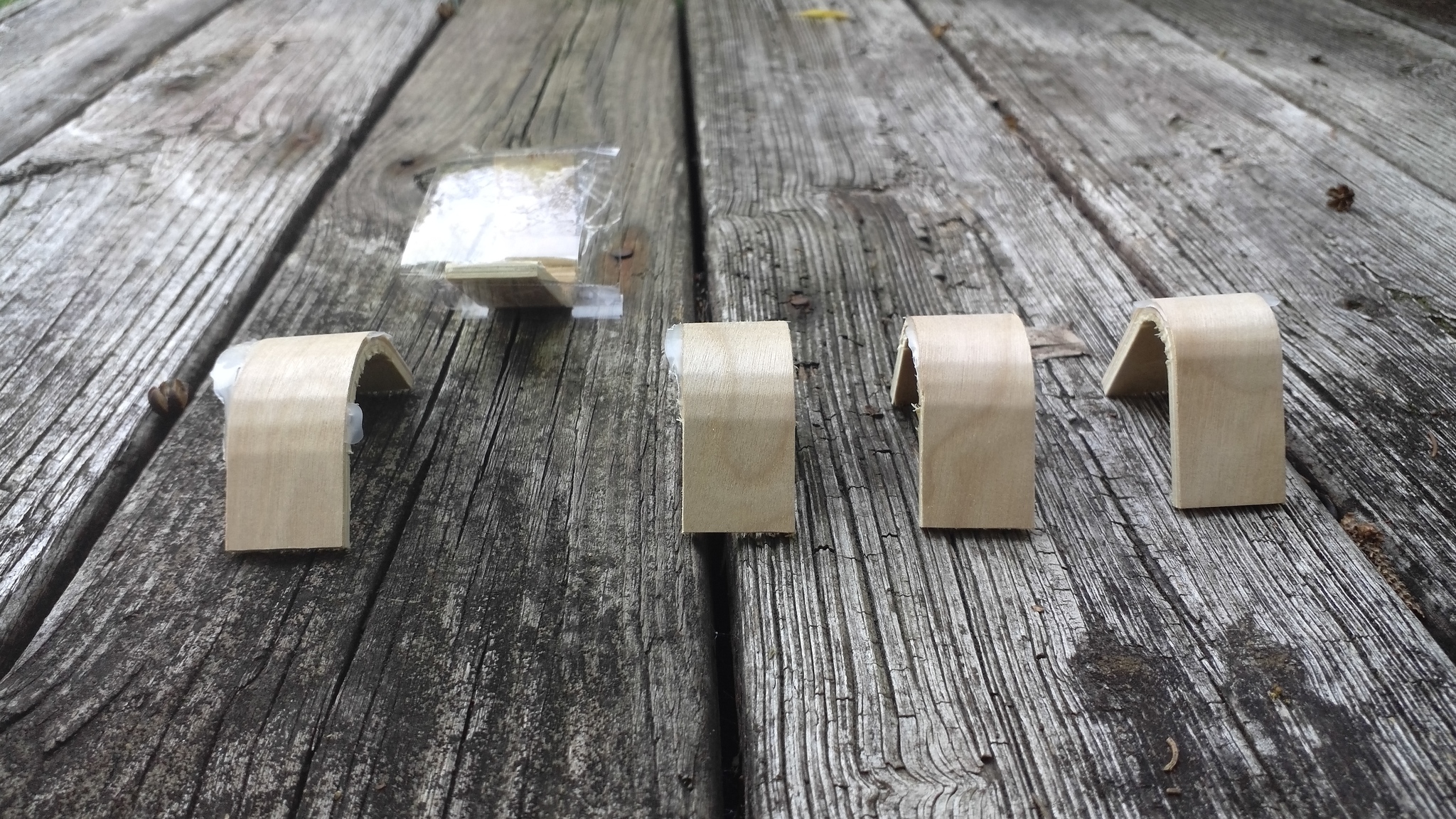
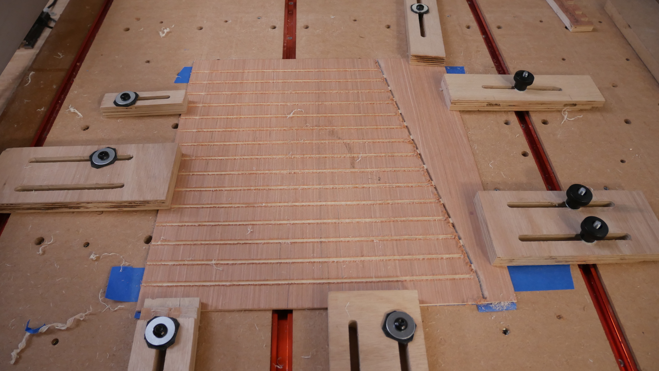
Anyway, here are the test cuts (the 1.5mm spacing which will be used for the next test is on the left, and obviously one should be careful when adding additional rubber bands to distribute them evenly):
Interestingly, they nest/stack well:
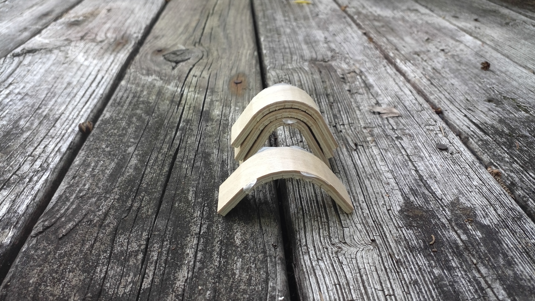
which might be an interesting joinery technique in and of itself.
Next up, a test cut of number of kerfs w/ 1.5mm spacing.
If anyone wants to experiment, here’s the OpenSCAD file:
test kerf multiples.zip (939 Bytes)
(that will probably get updated to increase the length of the kerf)
1 Like
Good tests,
Have you seen this example use of the kerf bending against a CNC machined matching mount?
3 Likes
Which bit did you get?
I’ve been using an Amana #4577 and will probably get the 10 degree 3/32" ball to try out.
2 Likes
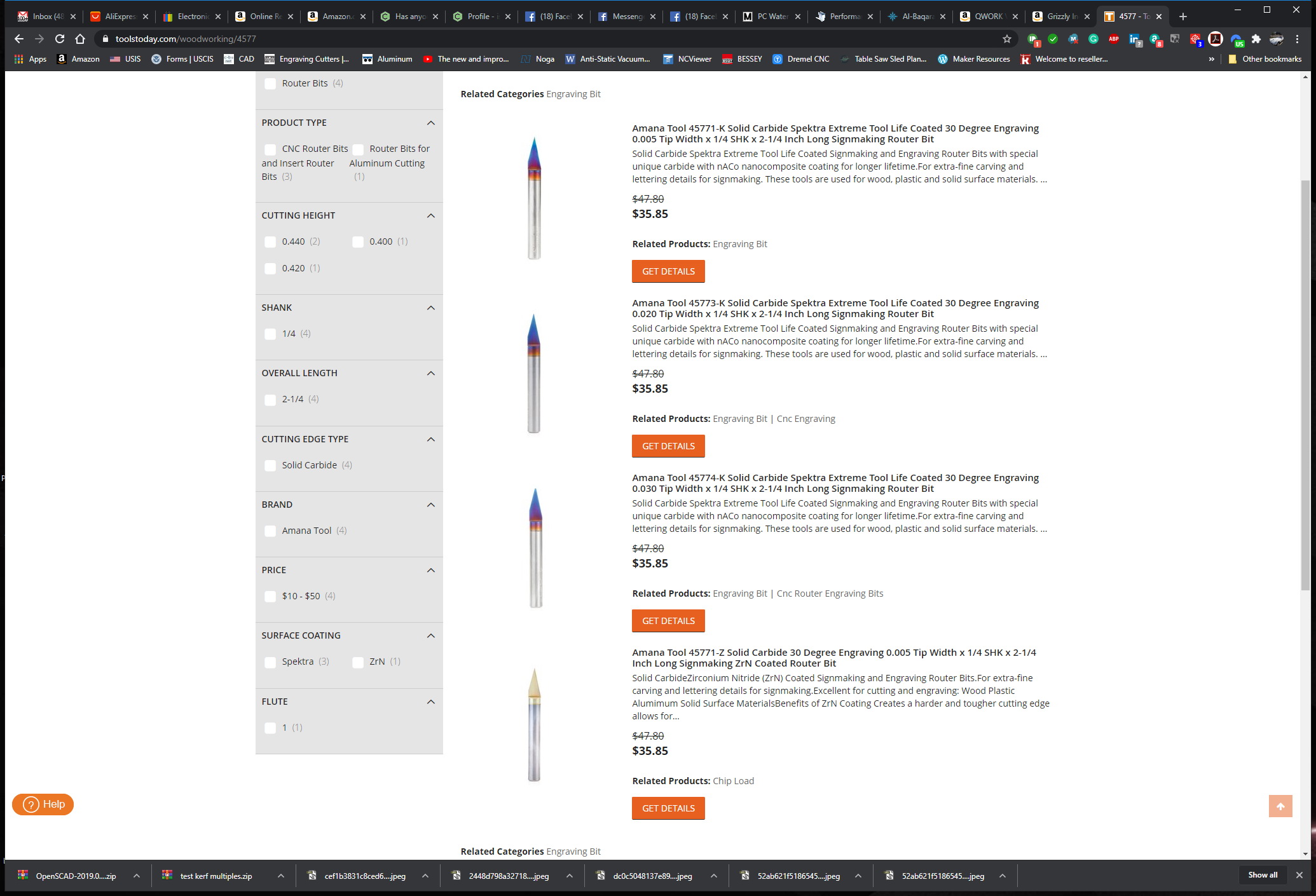
This one:
2 Likes
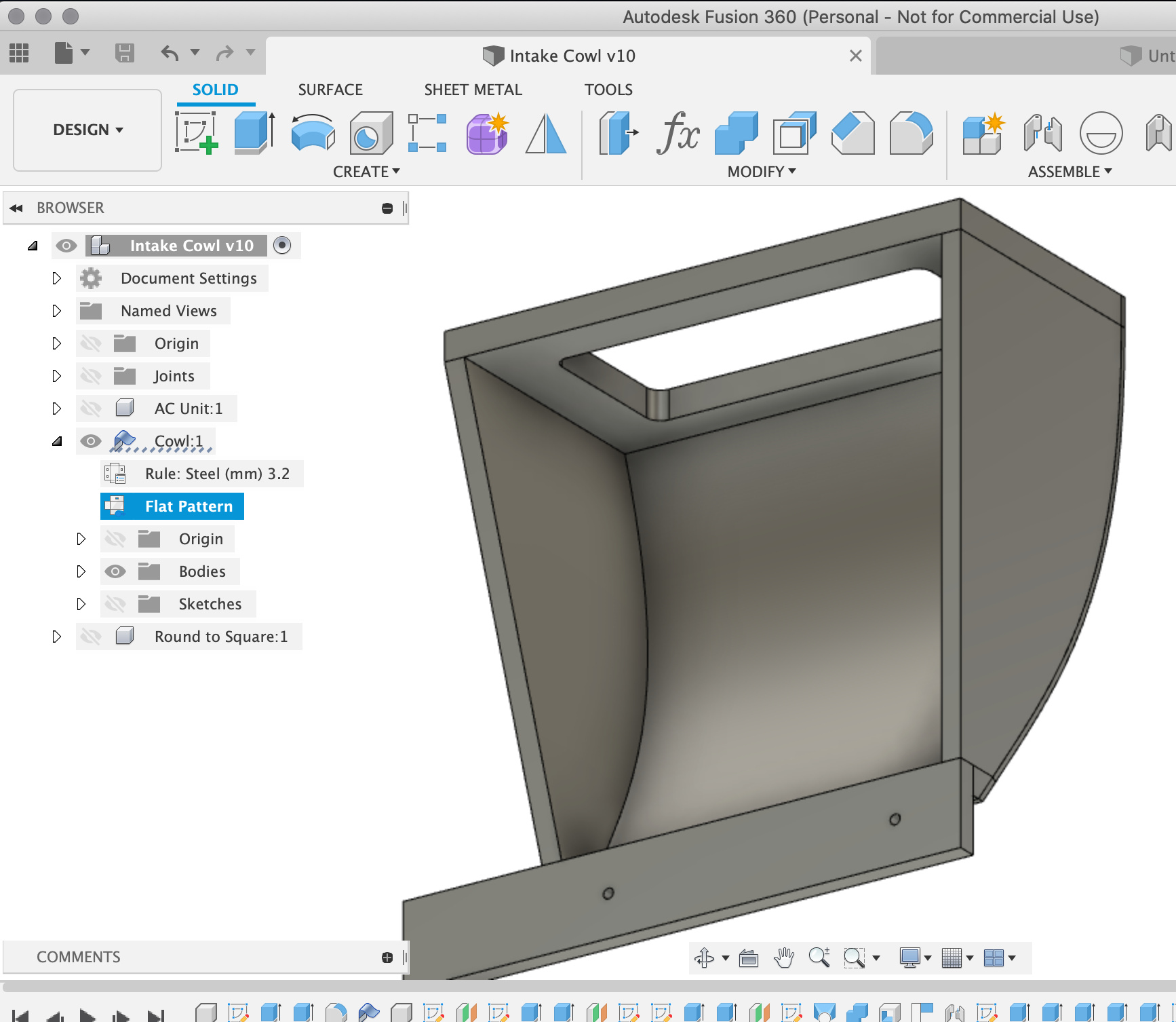
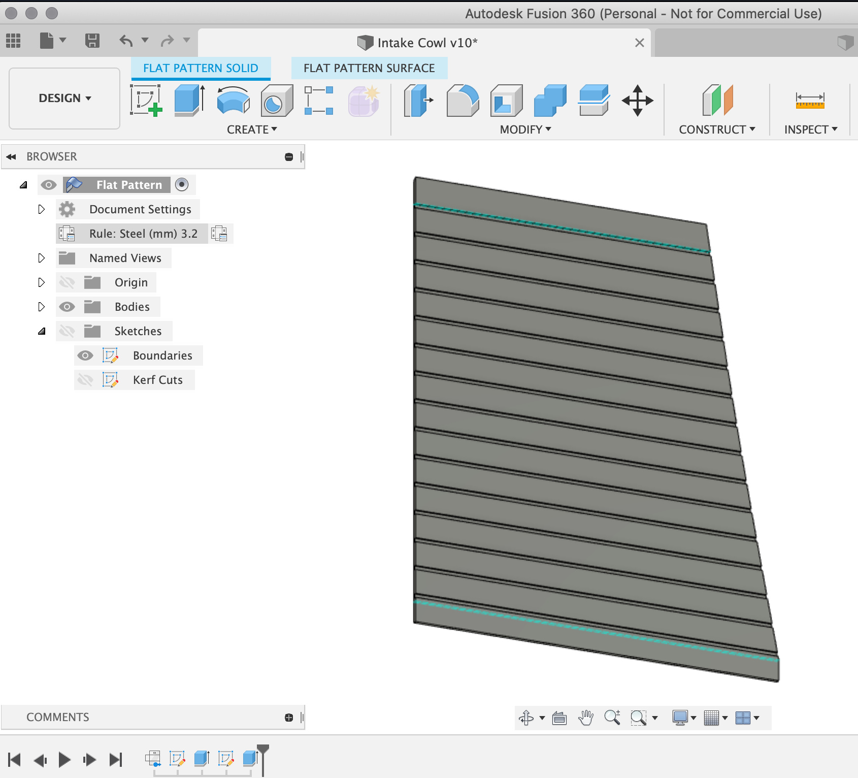
Thanks to this thread, whilst making up a quick air duct box I decided to bend some 3.2mm ply over the curved face and found that the sheet metal functions in Fusion 360 are pretty handy to un-bend your curved face into a flat profile to send for cutting on the machine.
I didn’t have a narrow angle V bit so I had to settle for cutting troughs through it with a 3.125mm at a ‘suitable’ pattern distance;
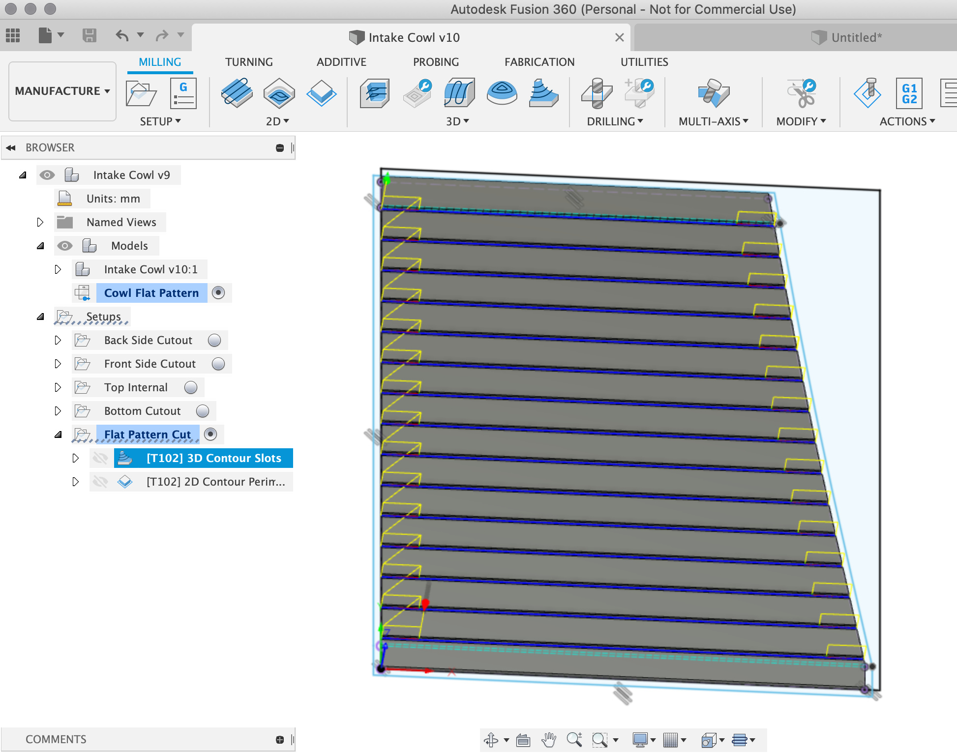
Which let me cut out the part pretty easily;
Lumpy surface, arc length and sagitta
Apologies if Will already covered this above, I had a look but didn’t see it.
Having glued it up and felt the digitised outer surface composed of straight lines and corners, it occurred to me that it might be worth calculating the V bit angle and cut to cut distance required to allow sanding to a smooth curve without going through your top veneer by calculating the sagitta of the chord-arc pairs
The arc length could be set based on the radius and the outer veneer thickness, or acceptably lumpiness of the curve by method 2 on that page " 2. Finding the sagitta given the radius and arc length" which should allow one to choose the inter-cut spacing to give a surface sufficiently close to a smooth curve. If that is too close together then a gap-filling adhesive or internal bracing may be necessary, if not, the angle of a suitable V bit can be worked out using Will’s calculations above.
3 Likes
@LiamN As you might know, I started this thread - basically just looking to see if anyone did what you just did, using CC. @WillAdams did what he does and took it to the lunatic-extreme (a phrase that should be associated with great praise and admiration). Still, the notion of angling the kerfs is interesting, but not too practical - if you ask me - because of the restrictions on the arcs that you can create given a specific angle on the cutter. The strength of flat kerfs being bent until their edges touch has been proven throughout time to be more than good enough…so I think you’ll be fine. There are volumes of references out there - and probably even some calculator pgms that do the work for you, regarding the spacing and depth for different materials to get different arc sizes.
- Gary
2 Likes
And thanks for the thread, or I wouldn’t have thought to curve that surface on the model and bend the ply over it.
I’m not worried about the strength in this instance. Having used the process, it seems that the inter-kerf distance might actually be dominated by what you consider to be sufficiently smooth curve rather than filling the kerf as the wood bends. That all depends on what you need out of the process.
If strength is an issue then bonding 2 or more layers would deal with the strength issue by making some of the kerfs internal anyway.
4 Likes
This topic was automatically closed 30 days after the last reply. New replies are no longer allowed.