Hi all, I haven’t reached a resolution yet with support@carbide3d, so I thought I’d post this issue here and see if any of you have thoughts.
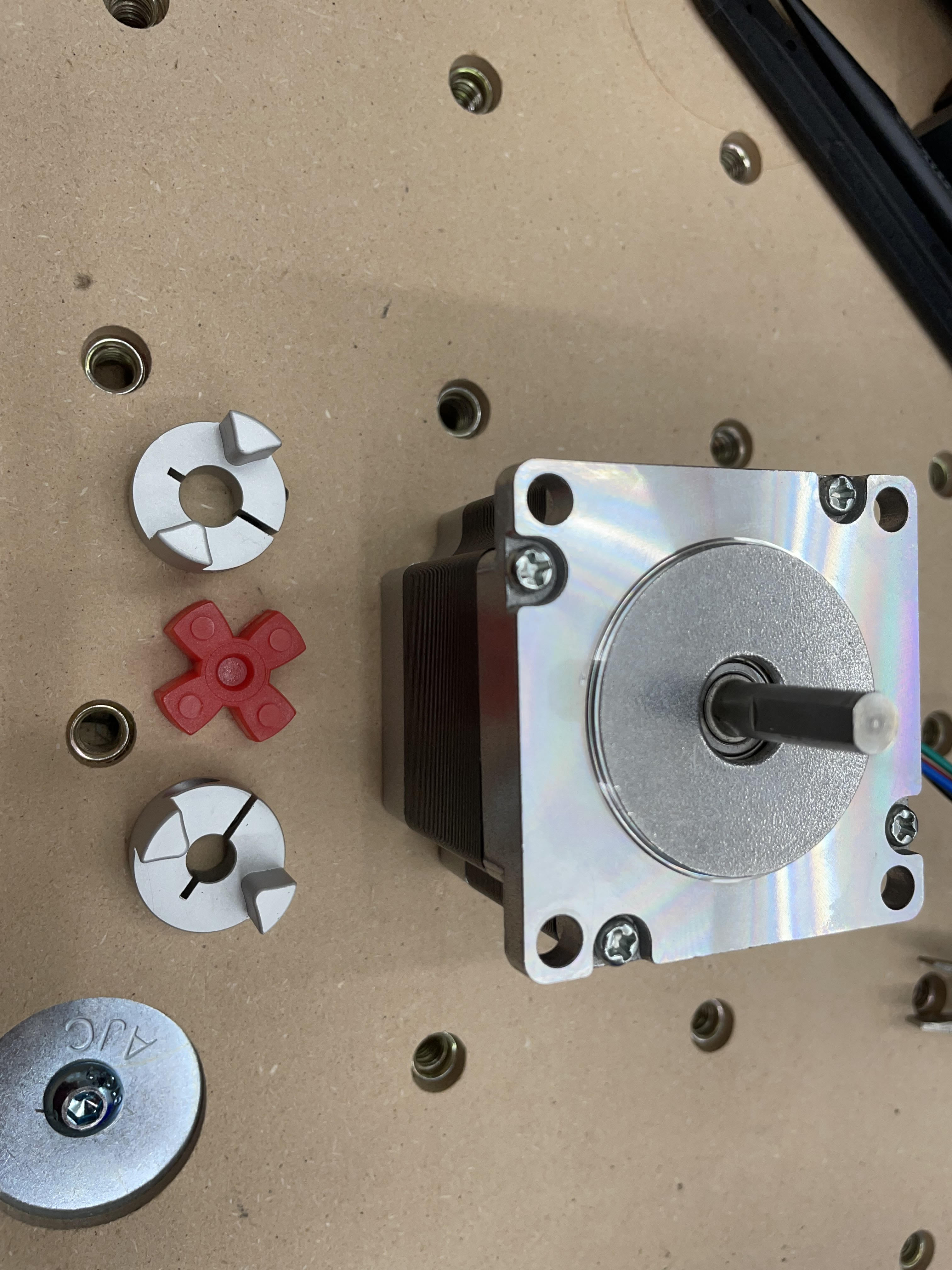
I’m working through the assembly of my HDZ for my SO3 XXL. I’m on page 18/62, step 1a of the manual – attach the Z motor and couple the motor shaft to the ball screw shaft.
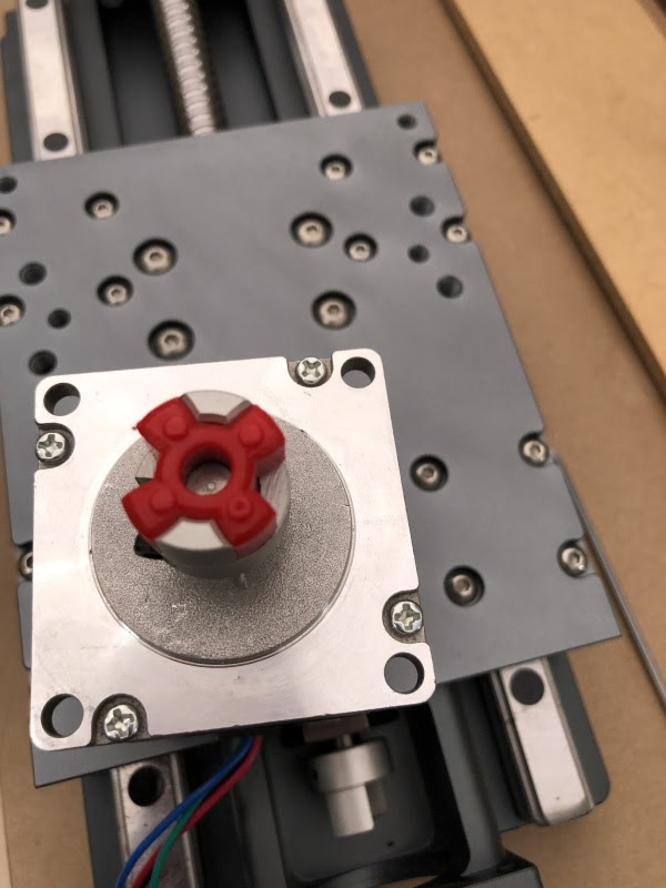
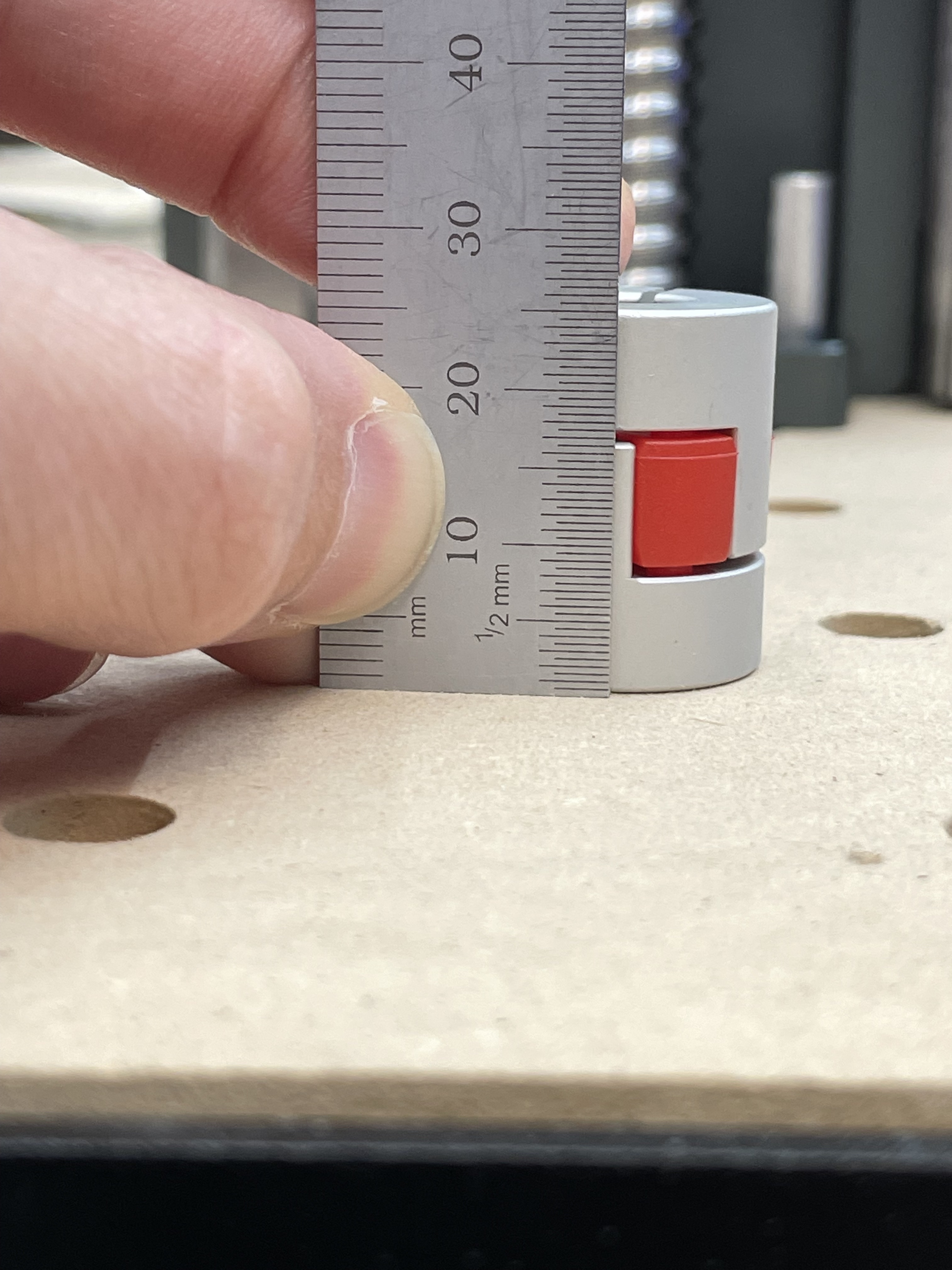
My problem is that it seems like the motor shaft is too long. It bottoms out in the shaft coupler, and I’m left with this 5mm gap between the motor and the mount.
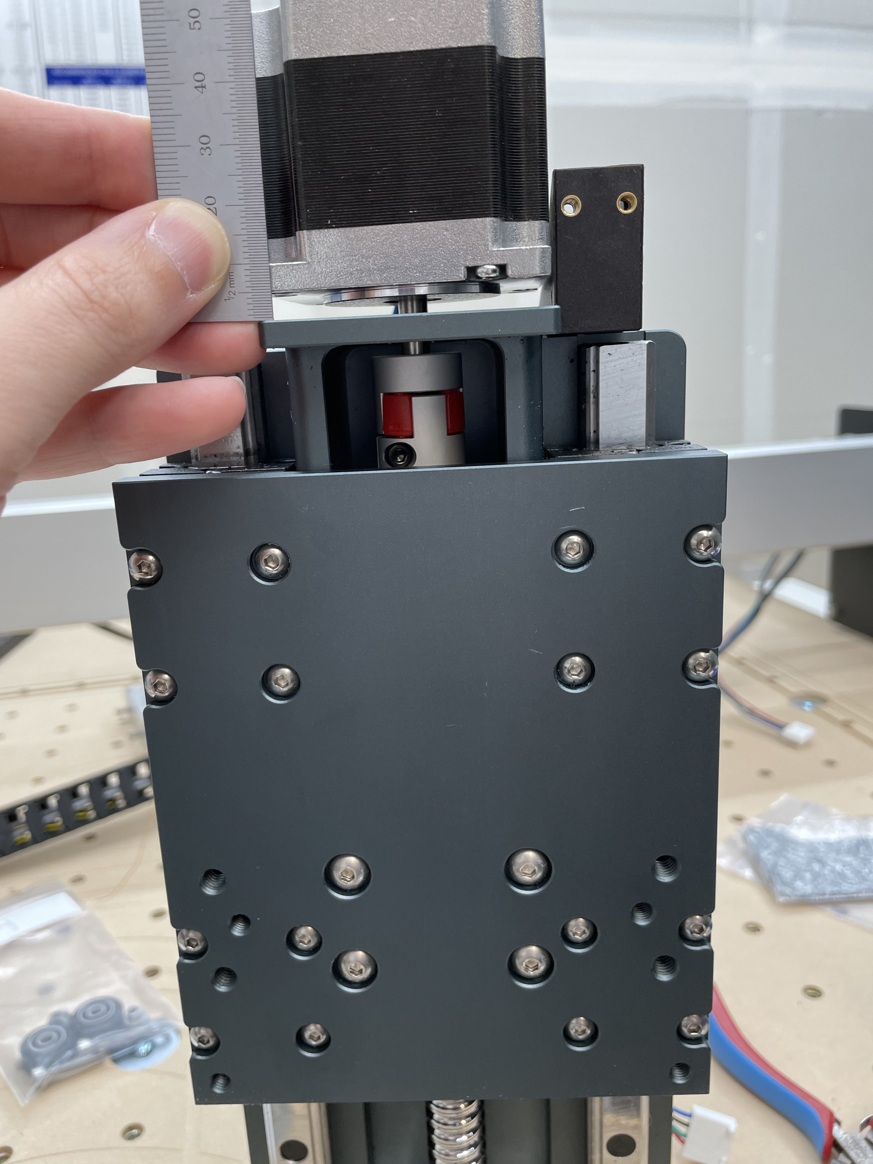
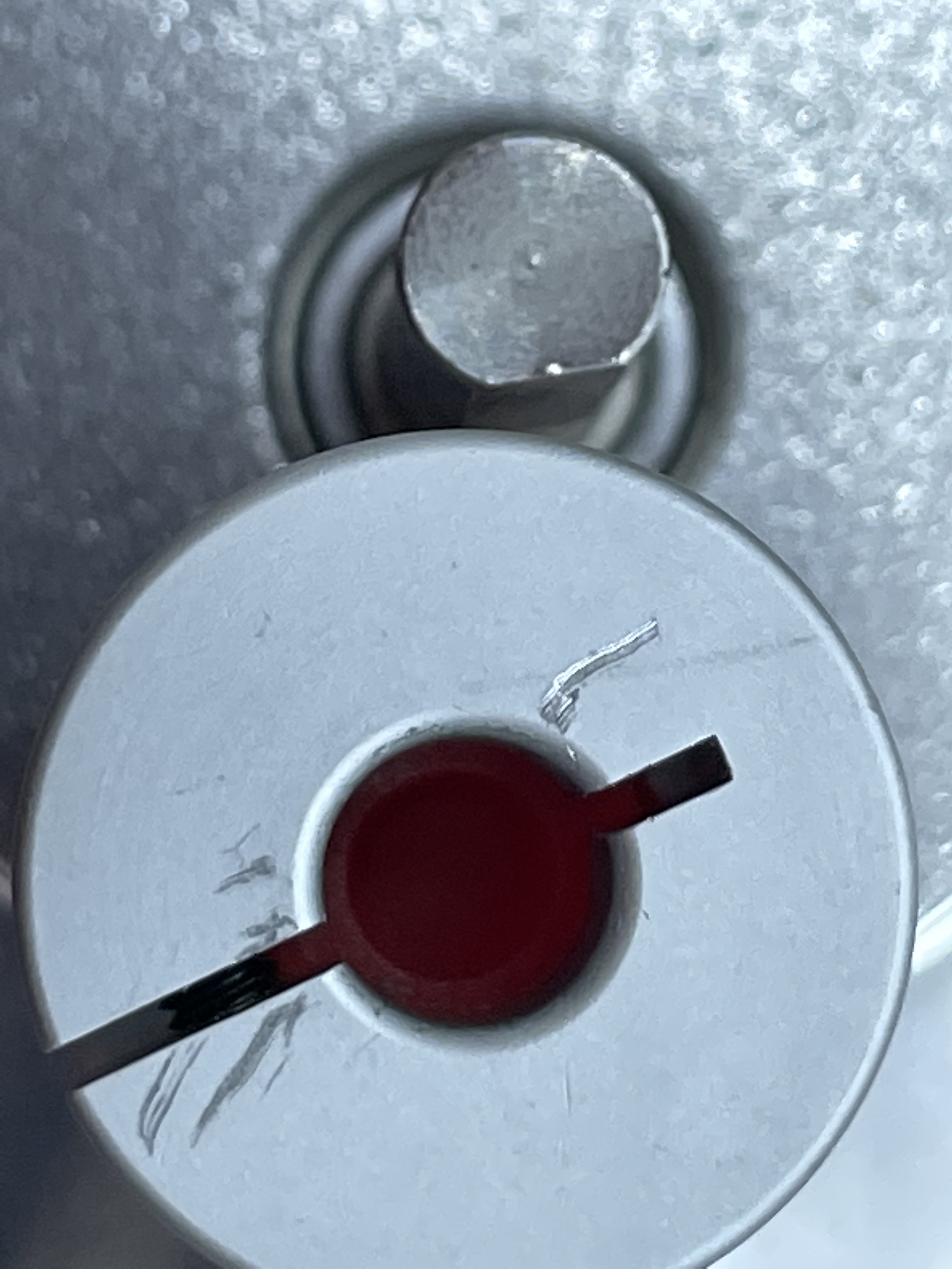
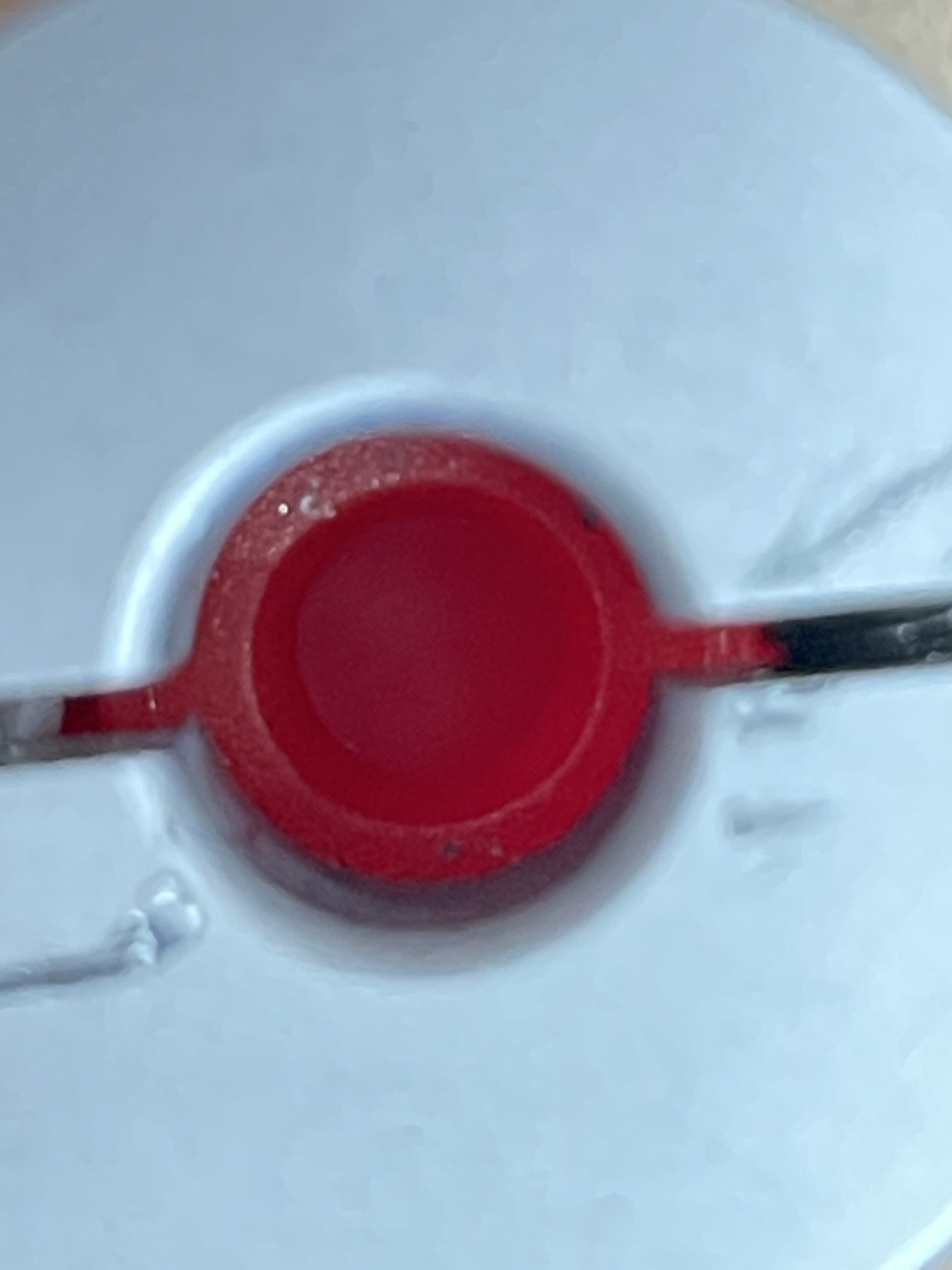
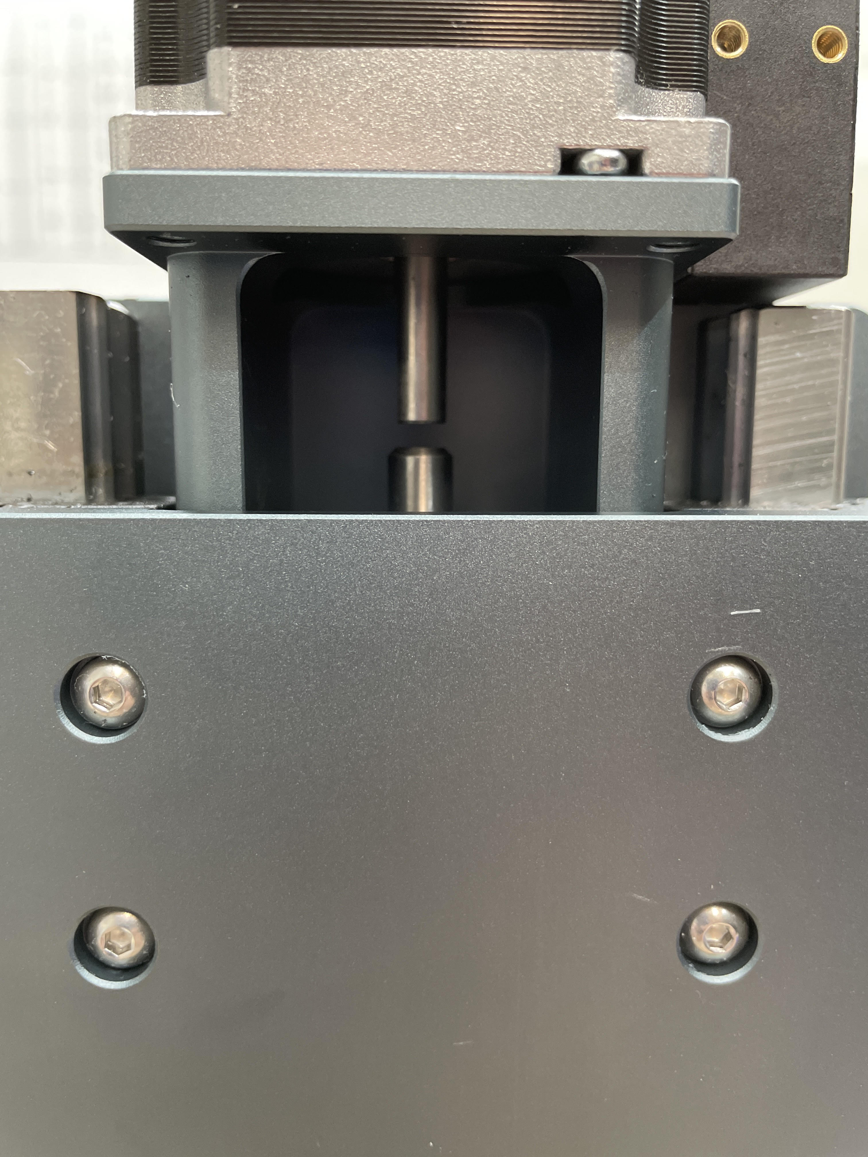
If I remove the shaft coupler from the equation, you can see that there’s about a 3 mm gap between the motor shaft and the ball screw shaft when the motor is sitting flush with the mount.
This isn’t going to fit. The red plastic in the middle of the shaft coupler is ~8 mm thick (8 mm plastic - 3 mm room between shafts = 5 mm gap between motor and mount).
Am I don’t something wrong? I’m using all stock parts purchased directly from Carbide 3D.
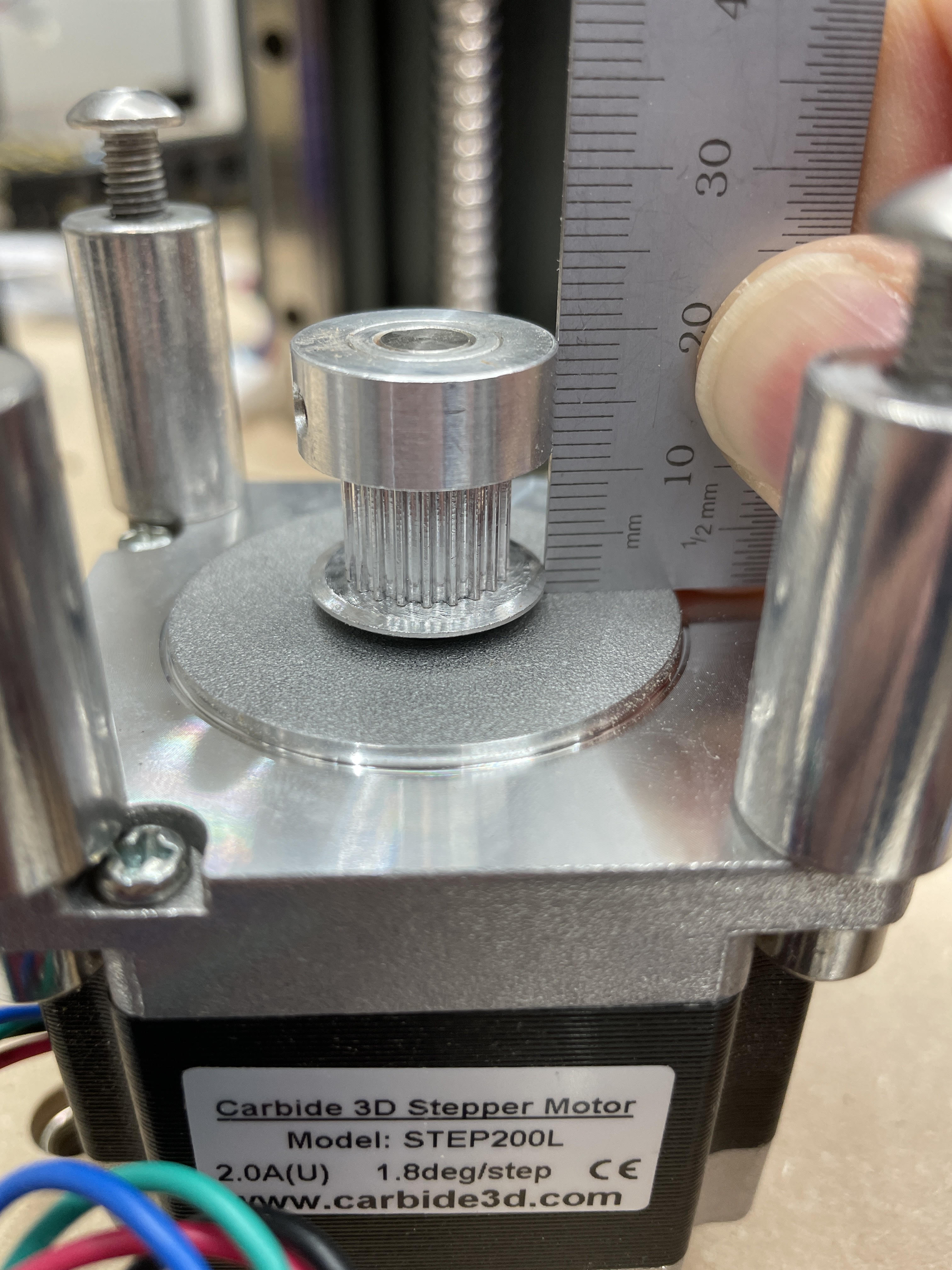
I thought my motor shaft might be too long (wrong motor?), so I dug up this post where @WillAdams points to a BOM for the machine and a product page with datasheet for the motor. The shaft length on the datasheet (21 - 1.6 = 19.4 mm) matches what I measure. That checks out.
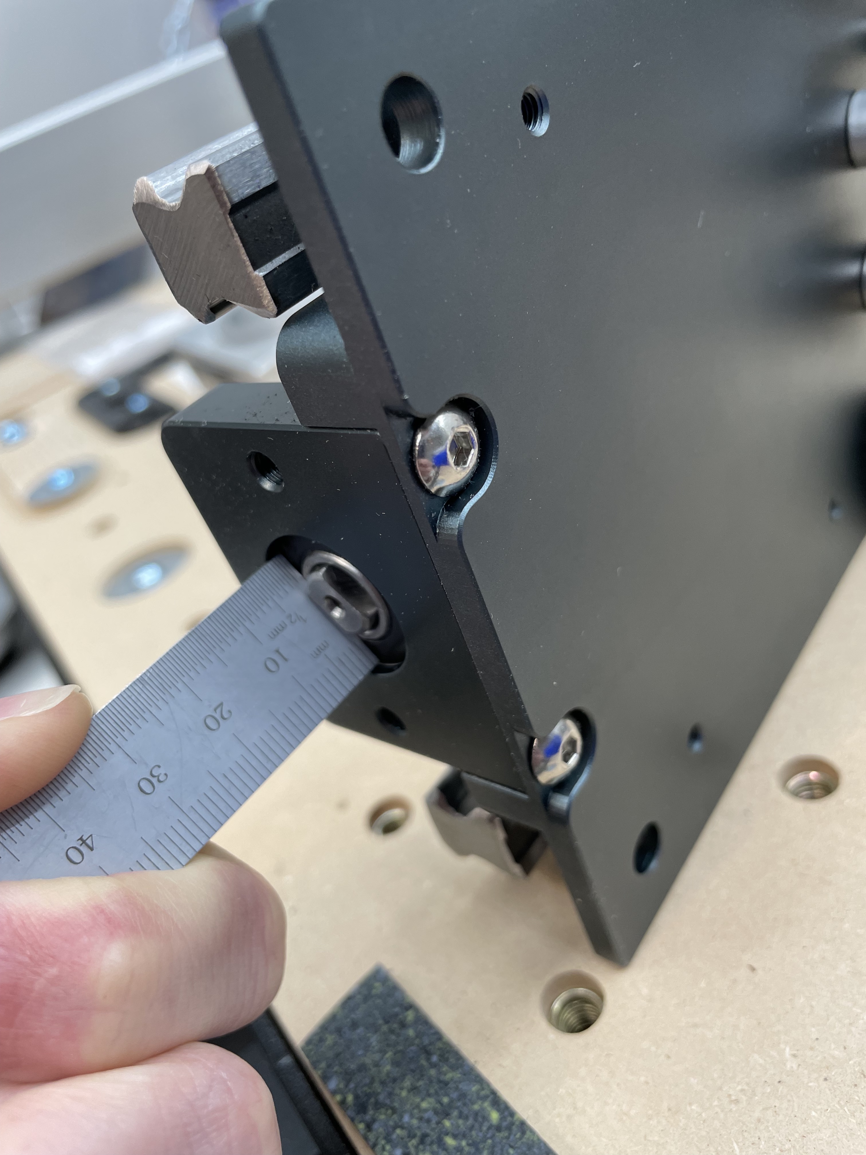
This photo below shows the X motor, but I’m certain I haven’t switched the X and Z motors; it’s the Z motor I’m trying to attach (and that’s in the photos above). All four motors have the same shaft length, anyway. The only difference between the STEP200S and STEP200L seems to be the cable length, 275 mm (S) vs 400 mm (L).
What else could be going wrong here? I’d appreciate your thoughts, because I’m stumped.
If you can easily get at it, how long is your HDZ’s Z motor shaft?
Does the part numbers on your Z motor match mine?
Do you (or did you when you set it up) see a similar 3mm gap between motor shaft and ball screw shaft, or was it bigger?
Does your shaft coupler look/measure the same as mine?
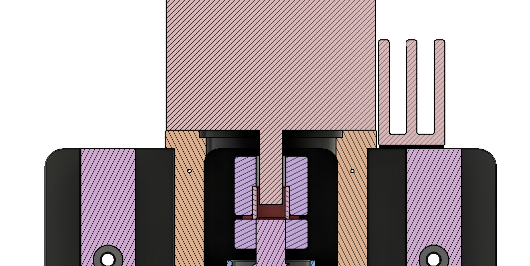
The only other thought I had is that the ball screw isn’t installed/seated correctly. If you look at Figure 14 in on page 18/62 of the manual, reproduced here for convenience…
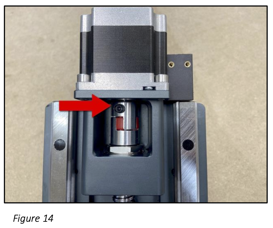
… you see that the bottom of the shaft coupler is just about flush with the top of that hex feature.
On mine, there’s a gap. Not the full 5 mm, but about 2.5-3.0 mm.
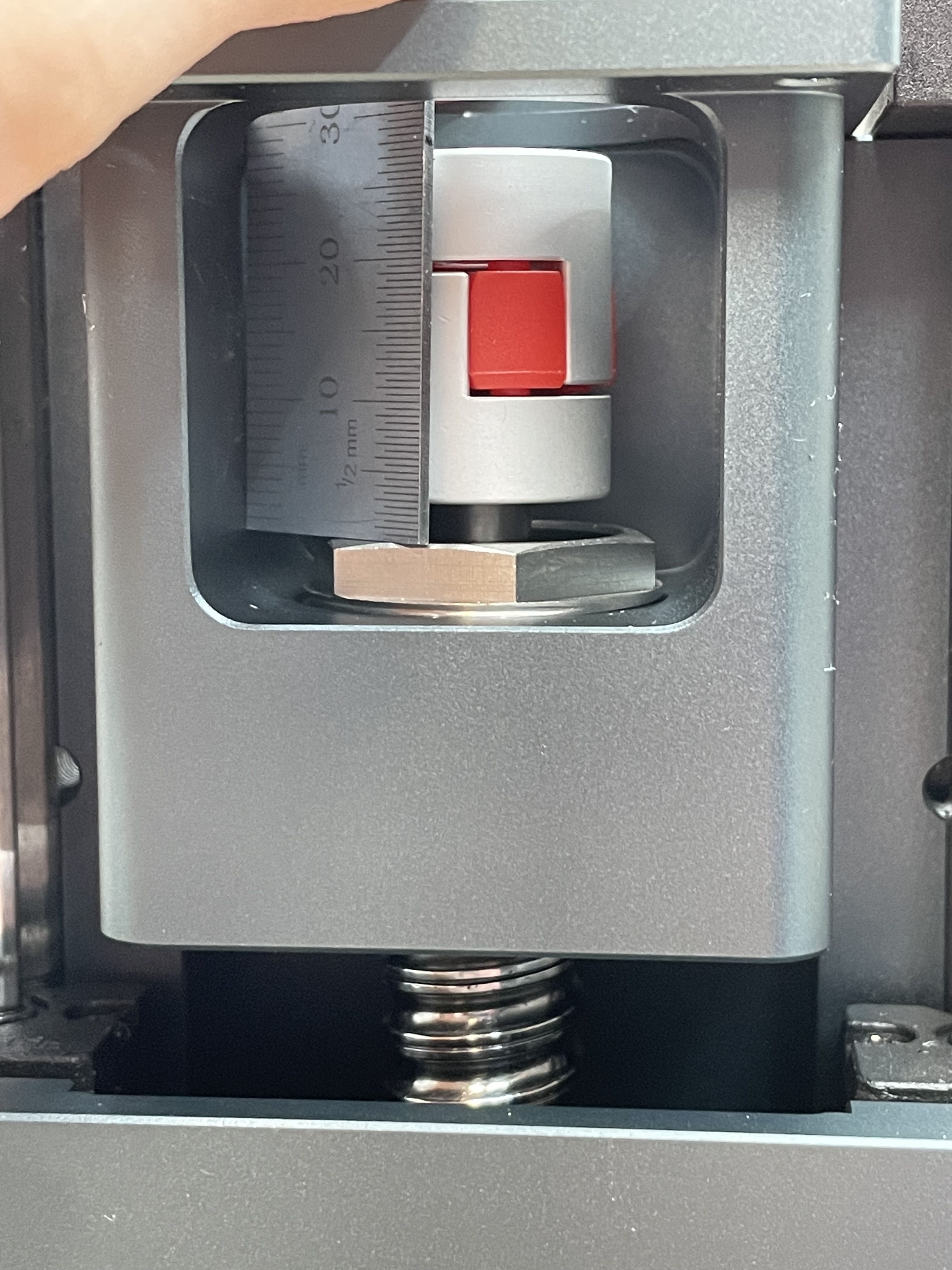
The remaining 2.0 mm might be down here at the bottom of the HDZ, if the router race of the bearing is meant to be flush with the bottom (doubt it, though, unless it’s a press-fit).
Also, when I rotate the ball screw by hand, it feels inconsistent around a single revolution. There’s a definite easy side of the rotation and a tougher side where it takes more effort to rotate. Another red flag with the ball screw. The ball screw stages I’ve worked with in the past (granted, they were Parker, so completely different price range) were butter smooth and consistent around their full revolution. How does yours feel when you rotate it by hand?
Alright, this has gotten long enough for now. Please let me know if you spot any red flags in the photos or descriptions I’ve provided, or if you want to see additional photos/measurements of other parts to check a hypothesis.
Thank you for the help!