What’s up Shapeoko Family!
Thought some would like to see the result if @Vince.Fab and @DanStory 's shapeoko had a baby. @Julien, don’t read any further lol.
As I started to do almost exclusively aluminum parts, my old CNC4Newbie Z-axis on rods and the wheel carriage plate of the X Y axis were clearly a bit too flex 
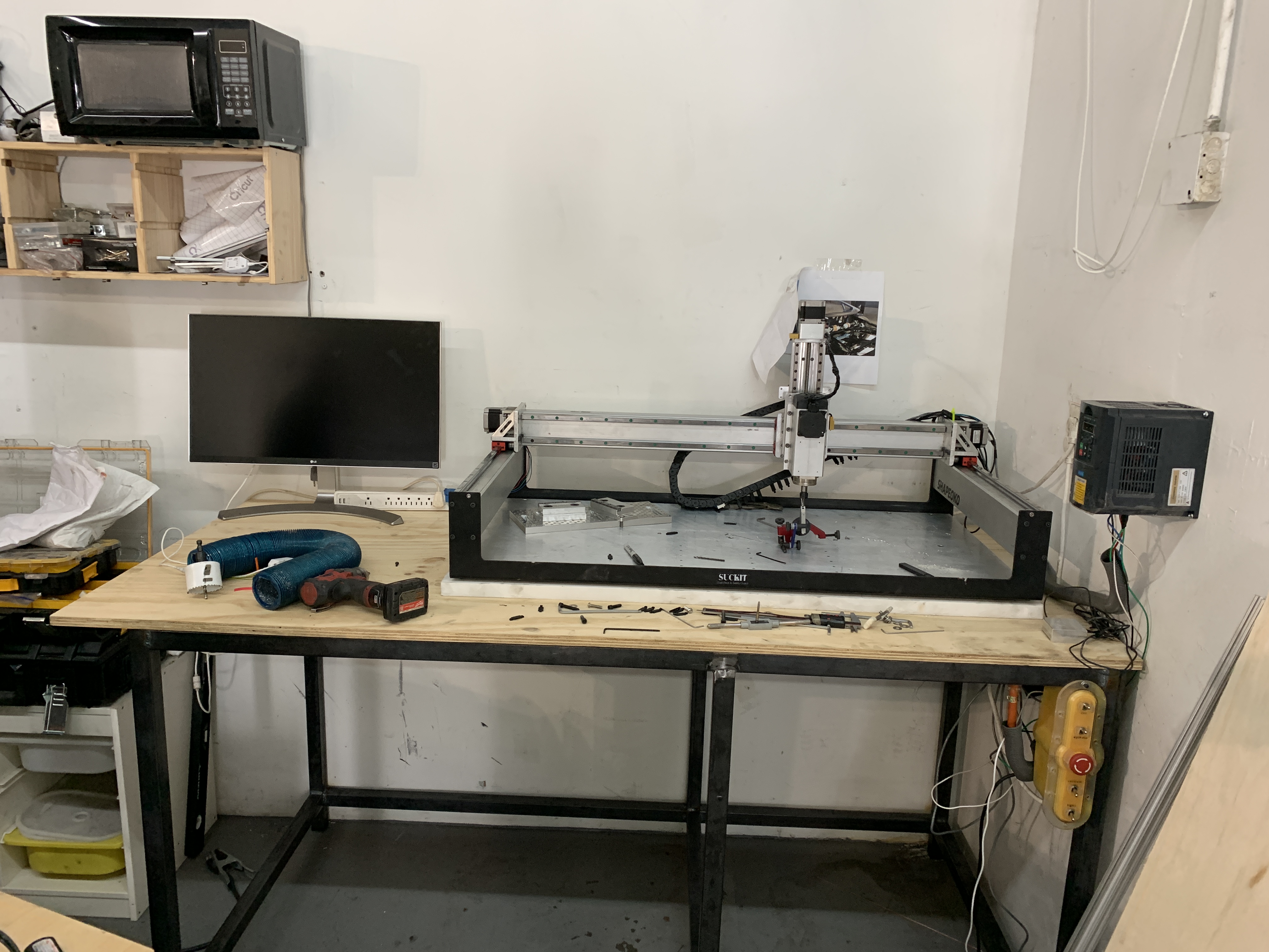
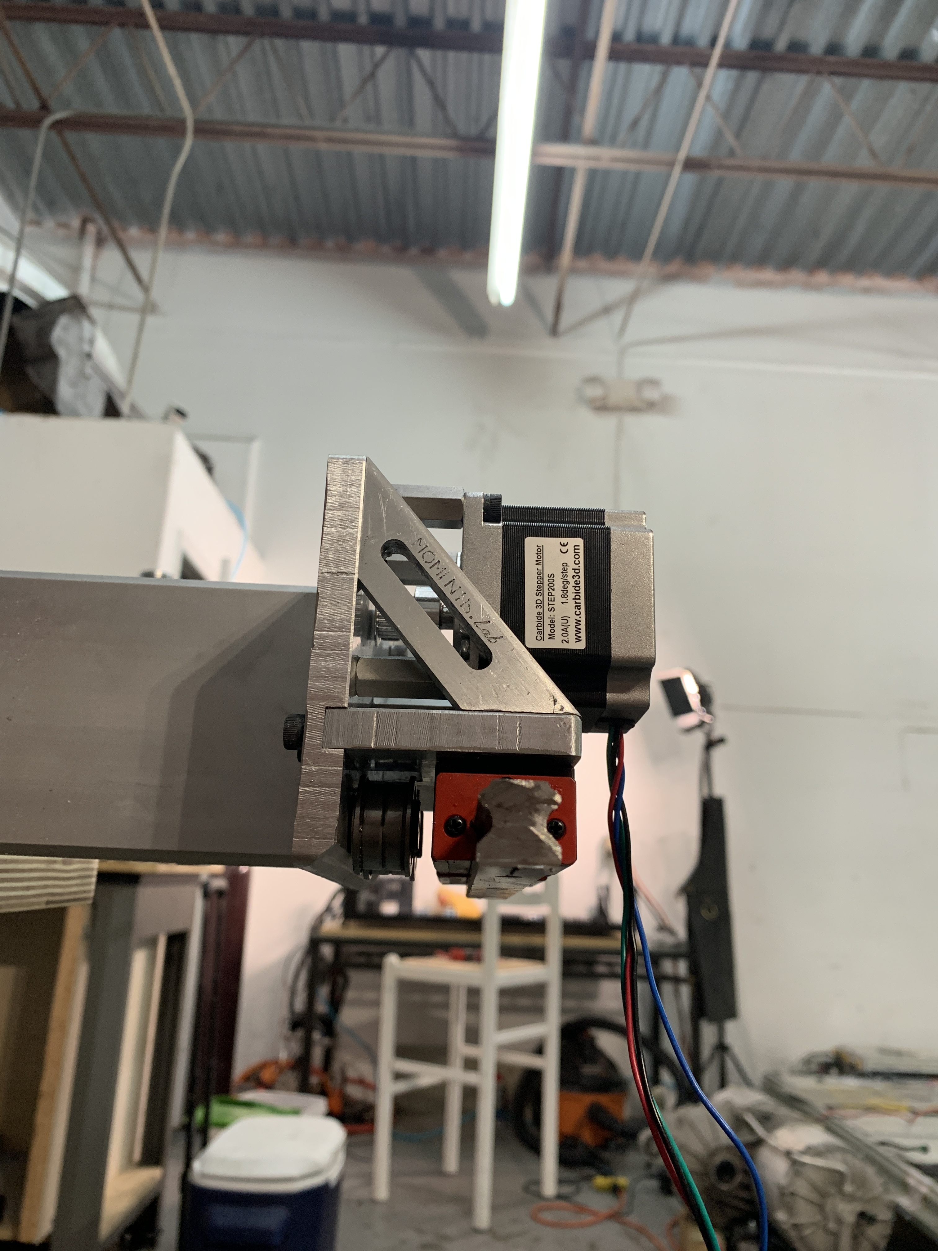
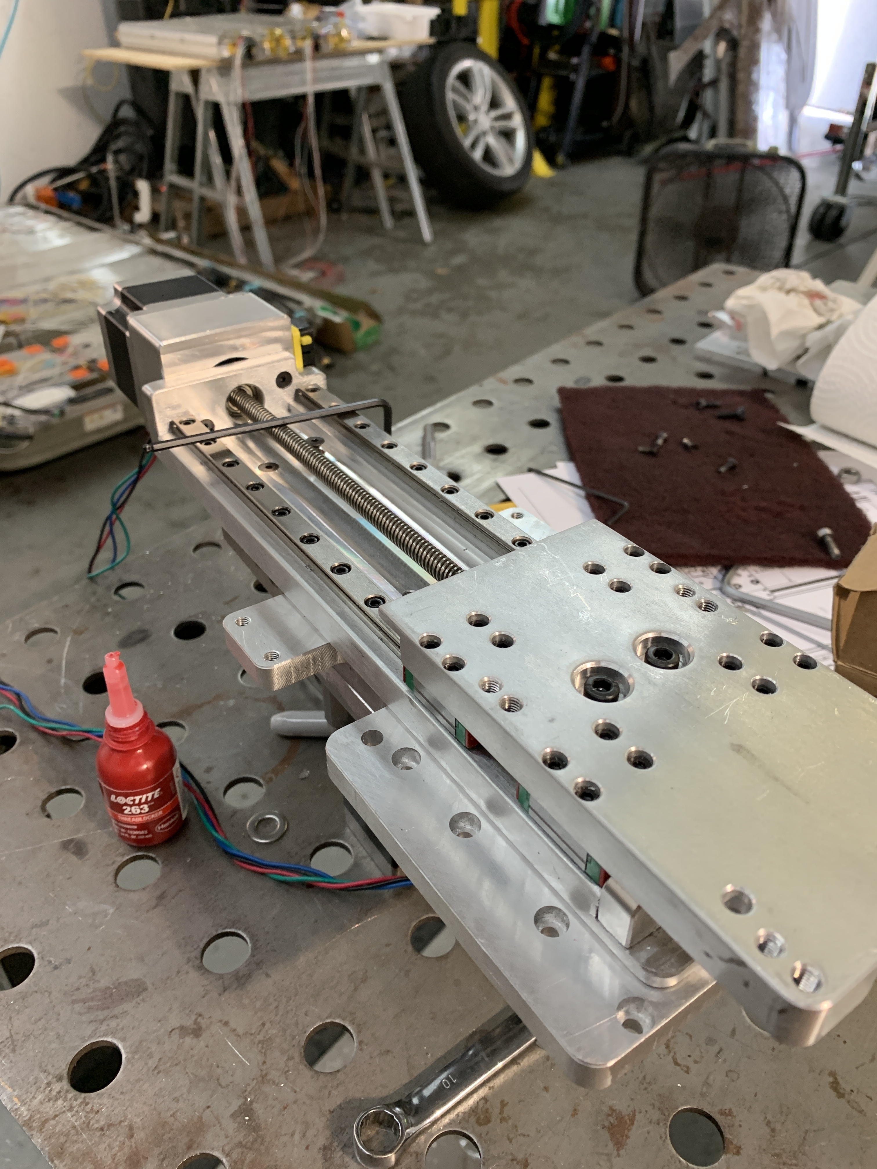
I kept my 9mm steel belts but upgraded to a modified version of Dan’s Shapeoko on Rails design. Here is my Shapeoko in its older self prepping its new bling.

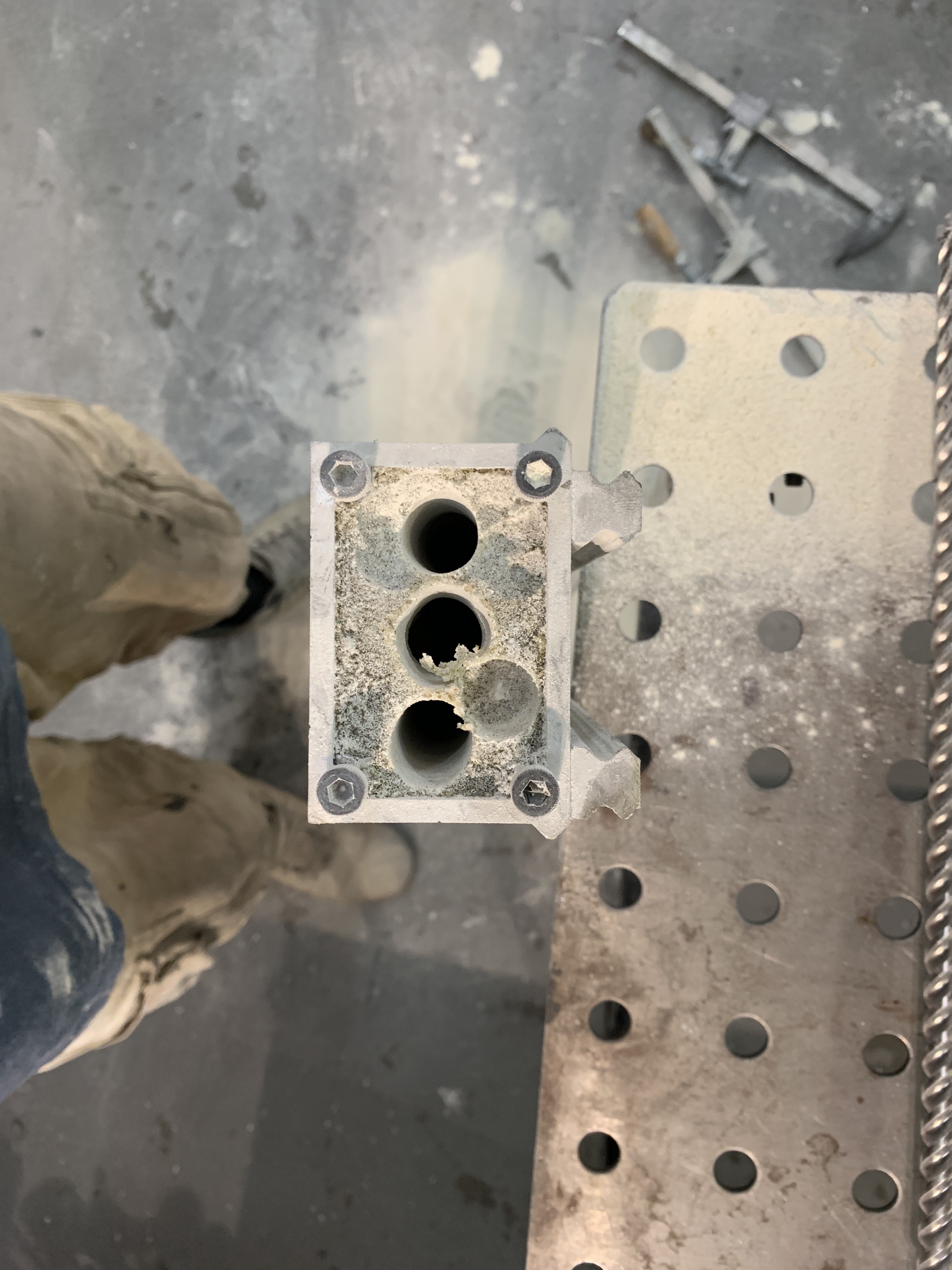
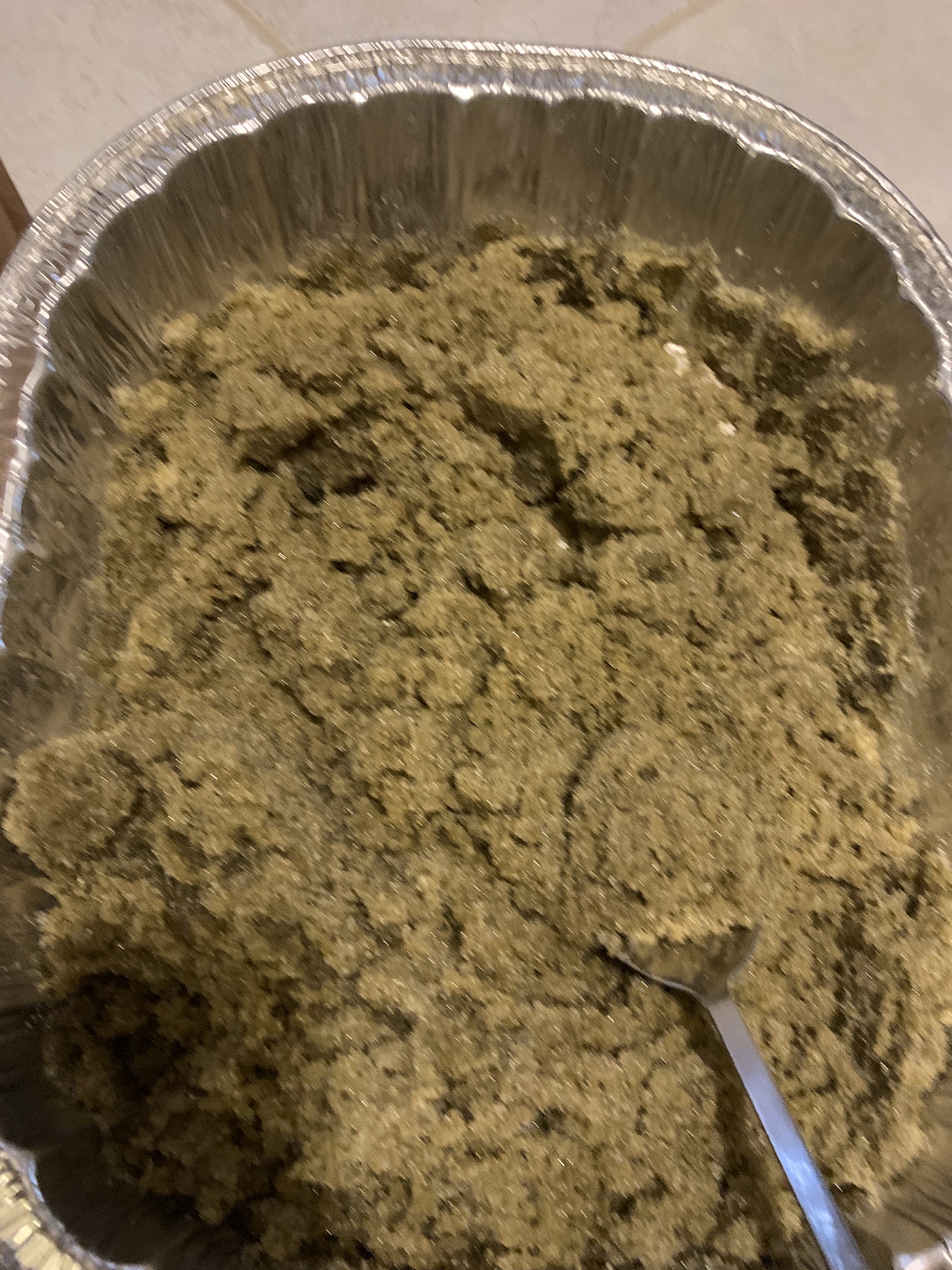
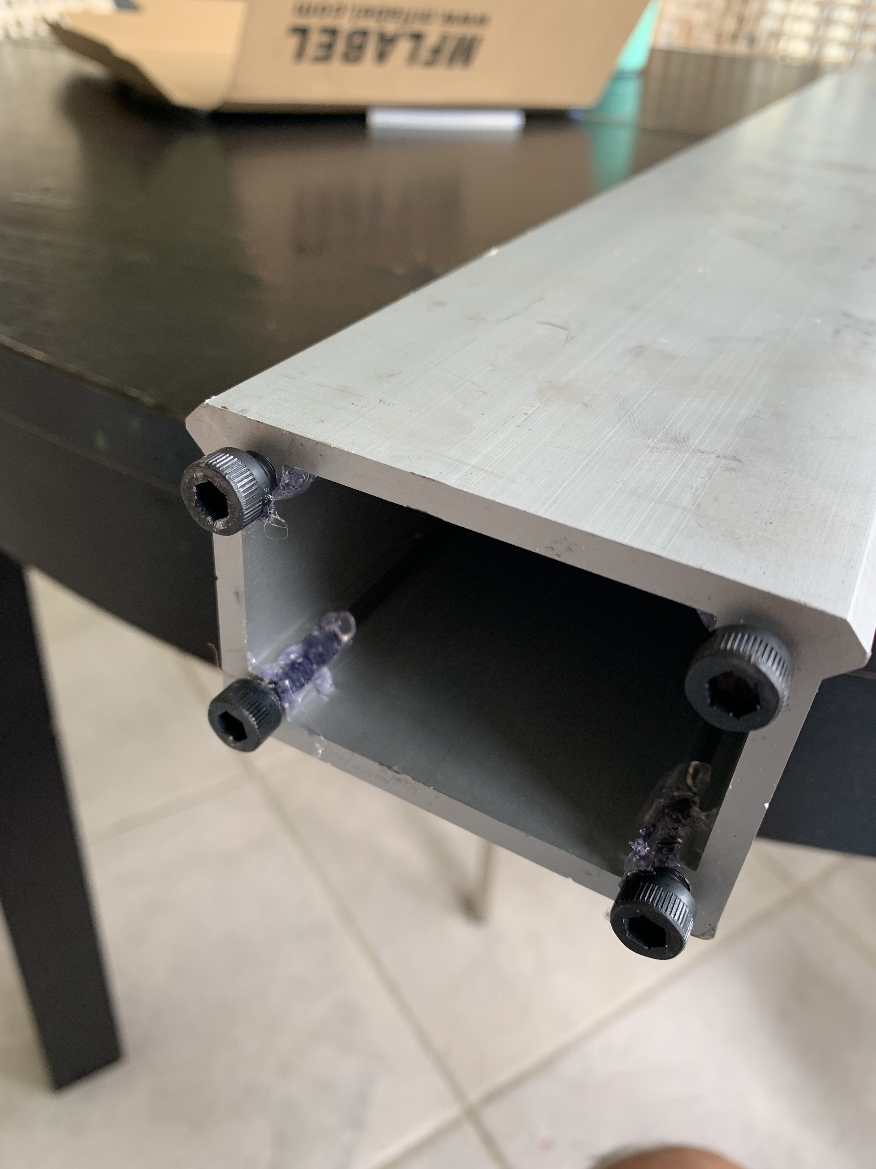
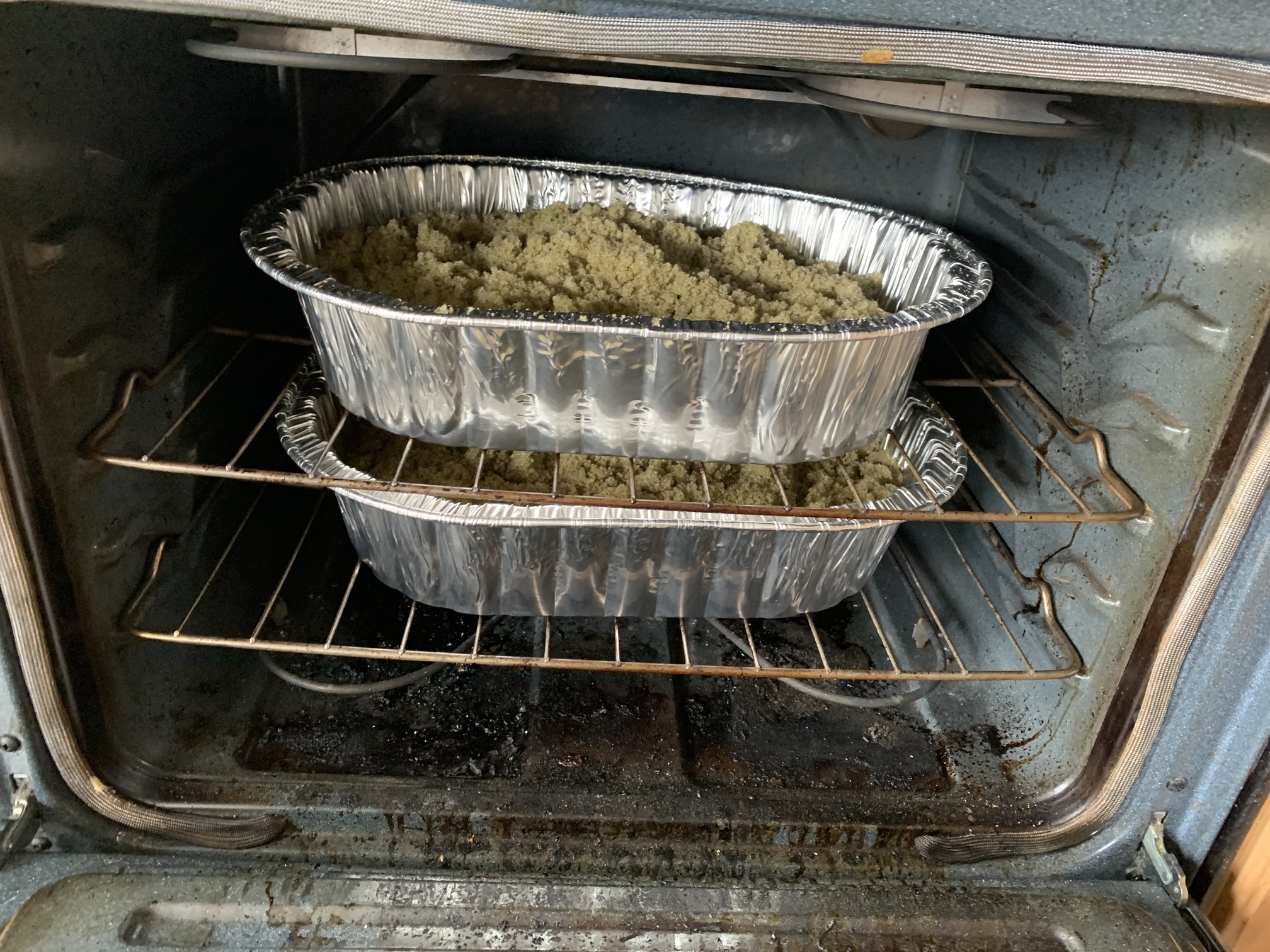
While my extrusions were disassembled, I made the decision to fill them with 80/20% sand/epoxy. I chose to fill X AND Y extrusions. Since I could not see anyone who did and knew the outcomes of filling the Y, I tried it. I have a very understanding wife (and amused kids) for letting me cook the sand for over 4h in the oven to get it really dry (should not take that long, but in South Florida, the level of humidity is pretty high)
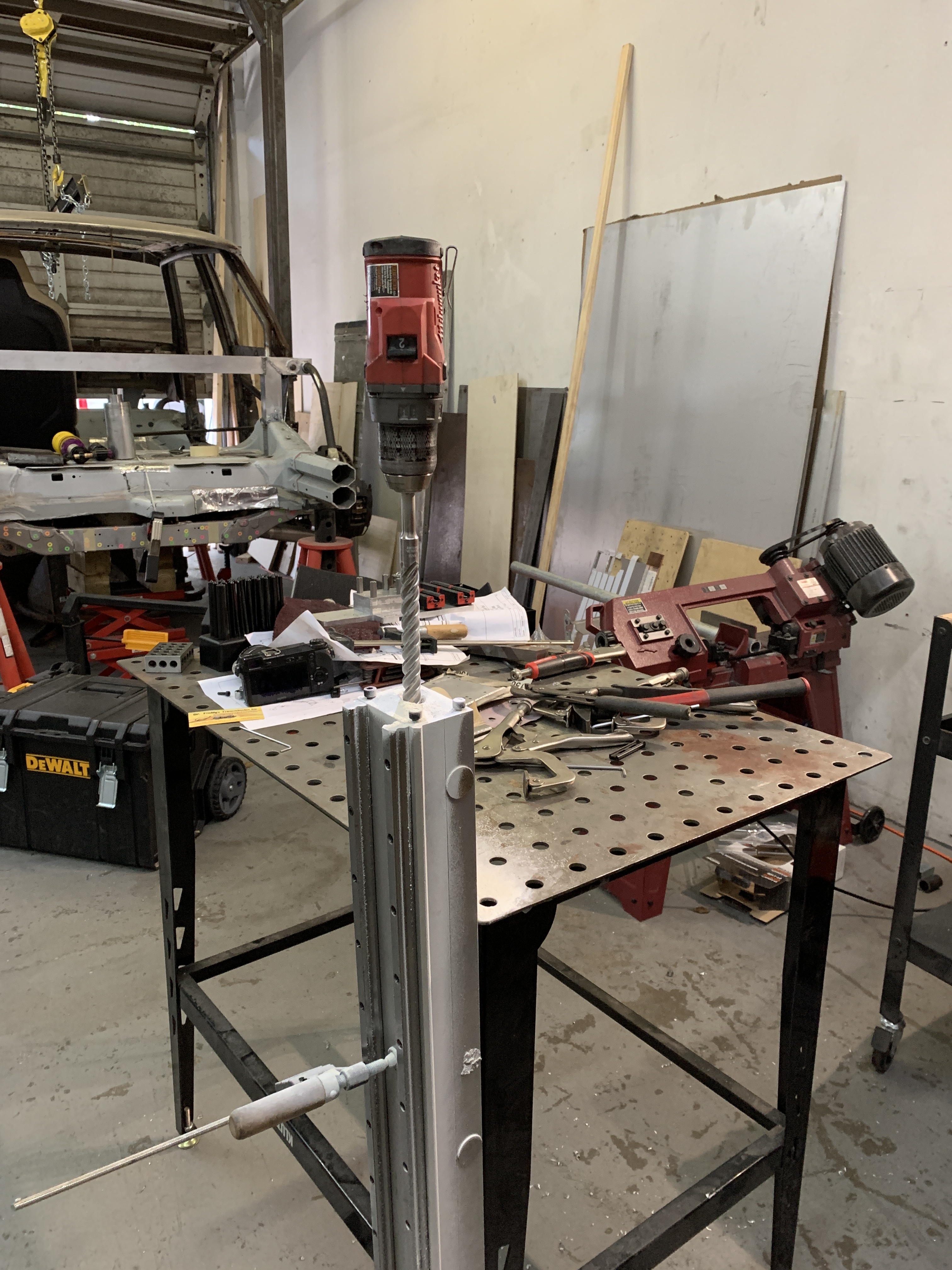
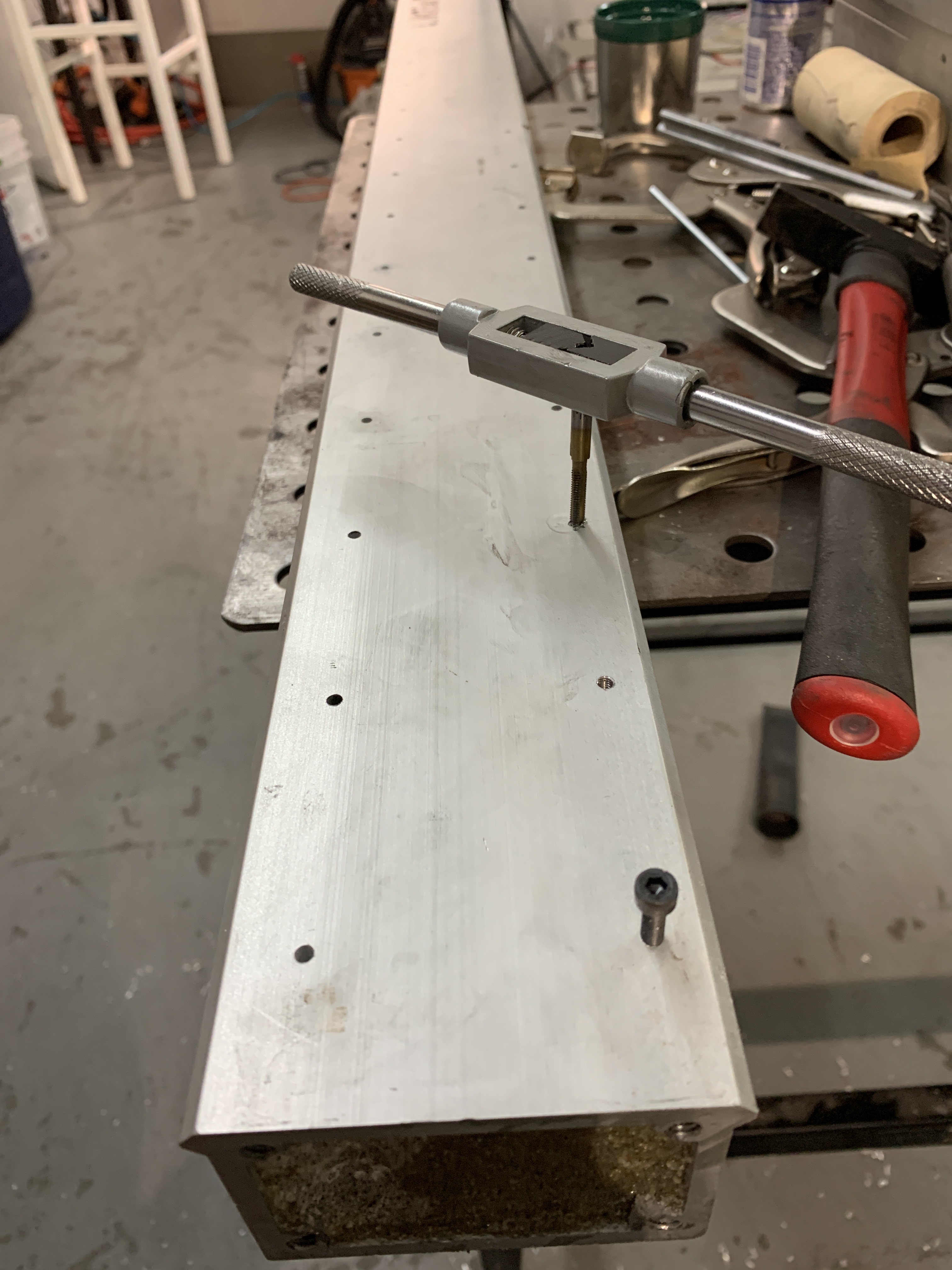
I can now say that it is impossible to move the shapeoko alone. I mean the extrusion are super heavy lol. I Then drilled three holes (1/3" - 24" drill, three holes by sides) to lighten it a bit. I don’t have a good scale, so I can only say “some” weight was lost.
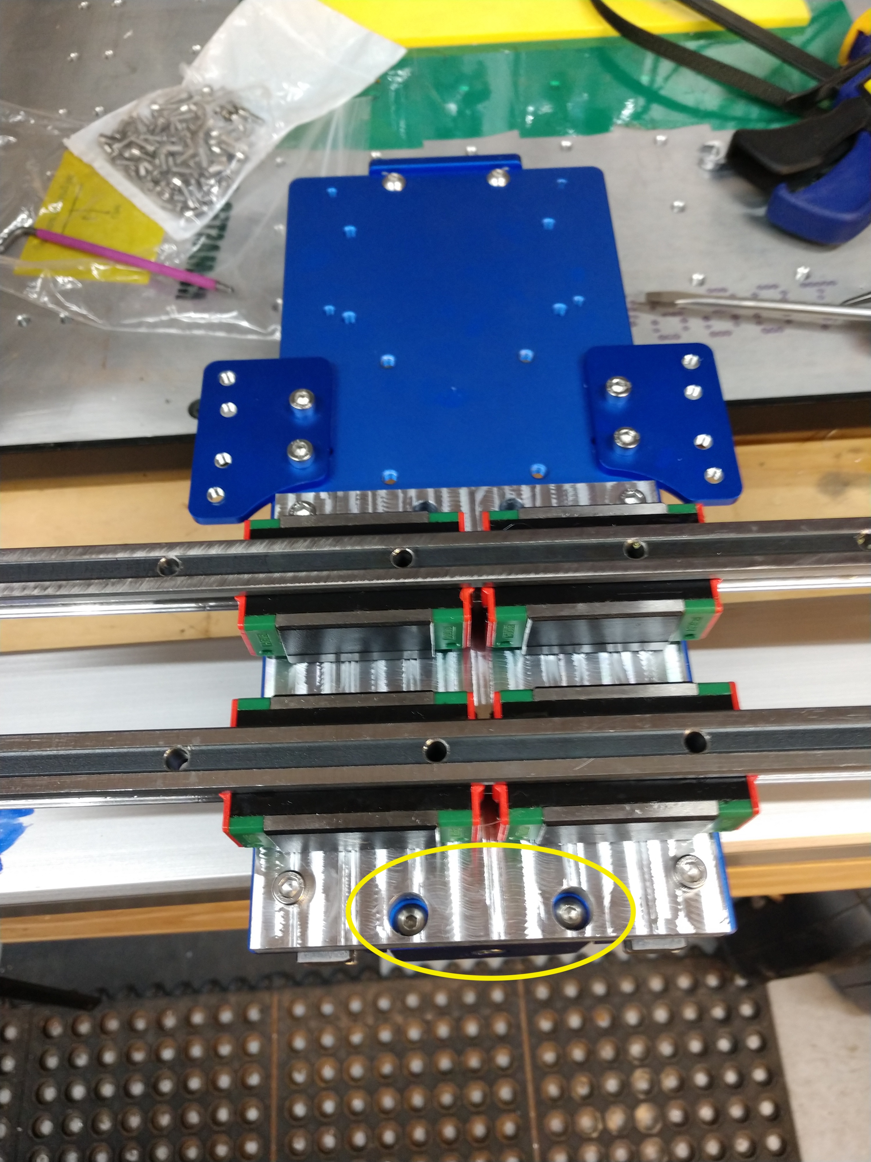
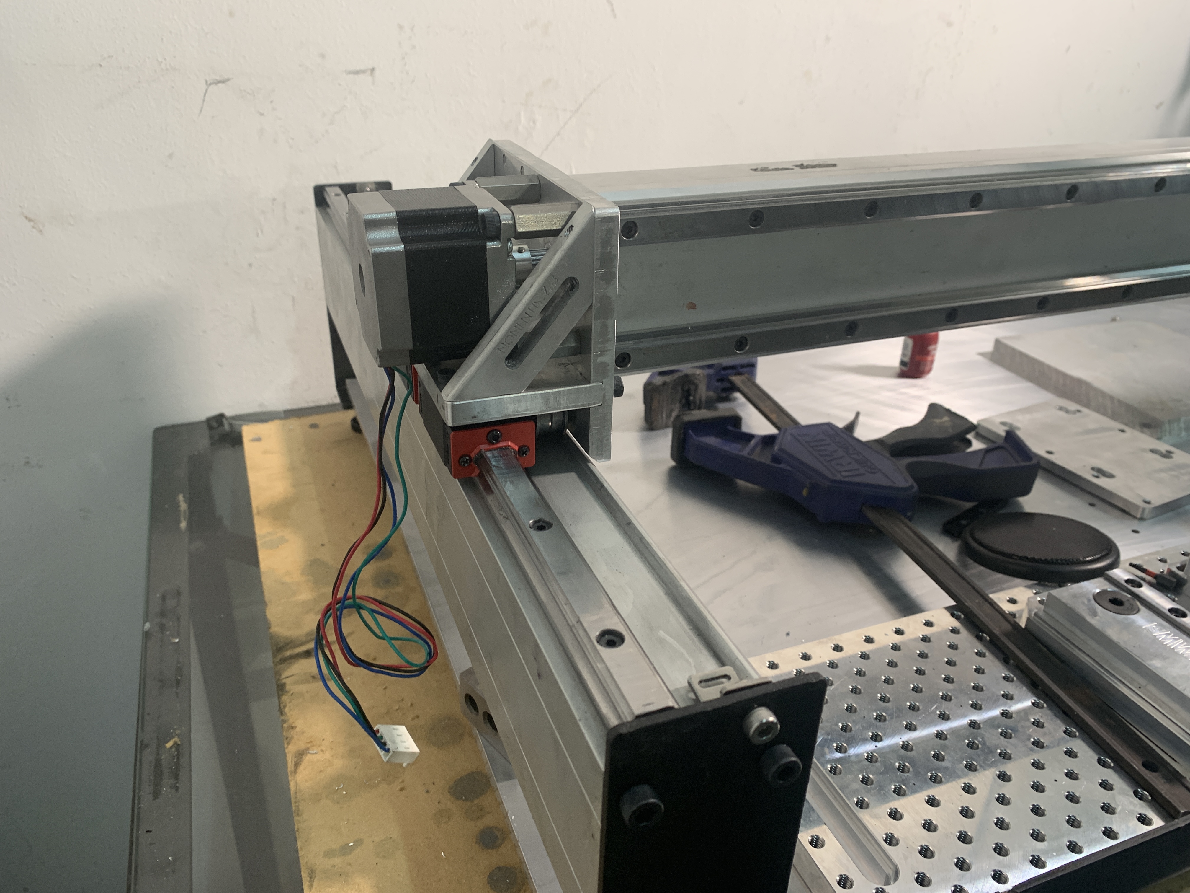
Assembly of the carriage blocks and rails took me the good part of two days.
I incorporated proximity switches that @Luke mentioned in a previous post. I knew I had to upgrade my steppers, one was grinding and the extra weight needed some more torque.
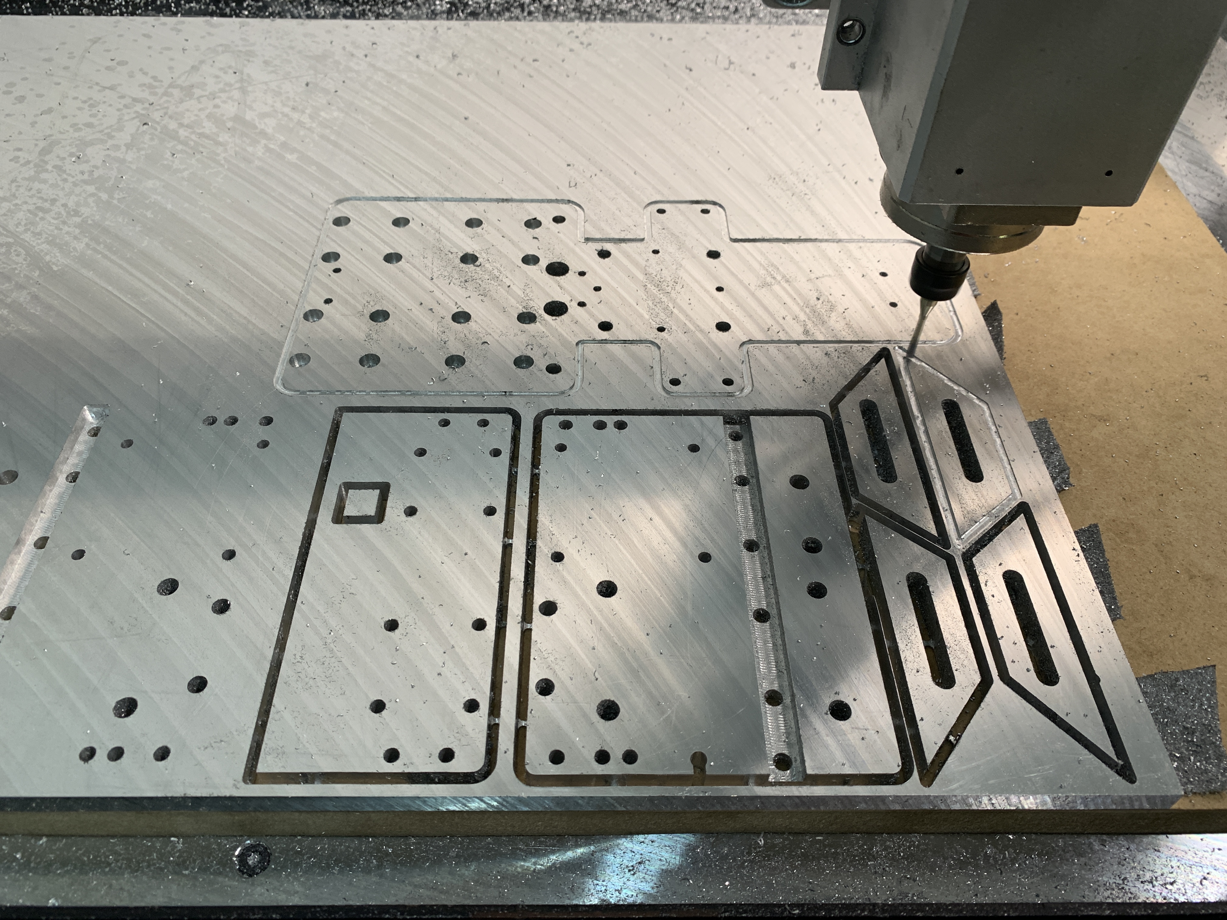
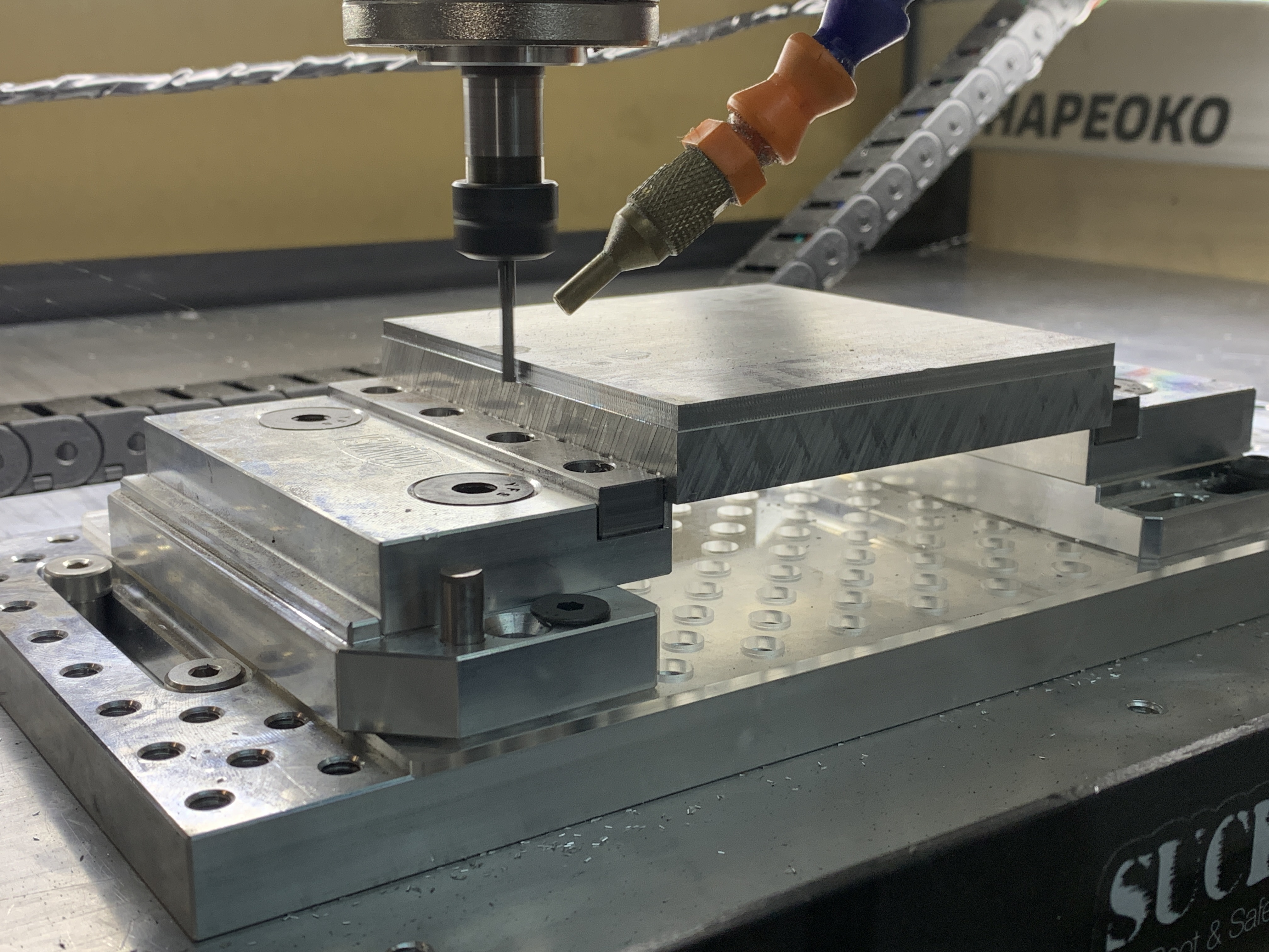
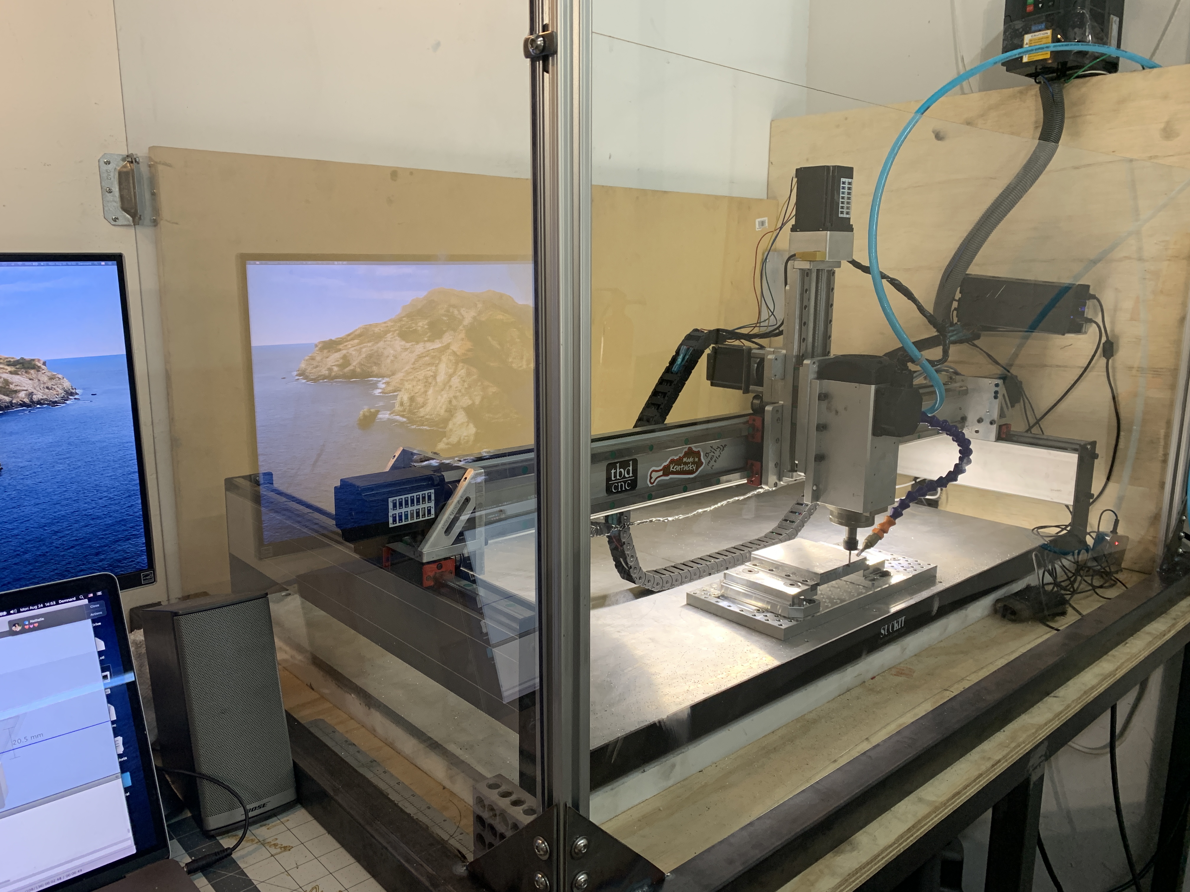
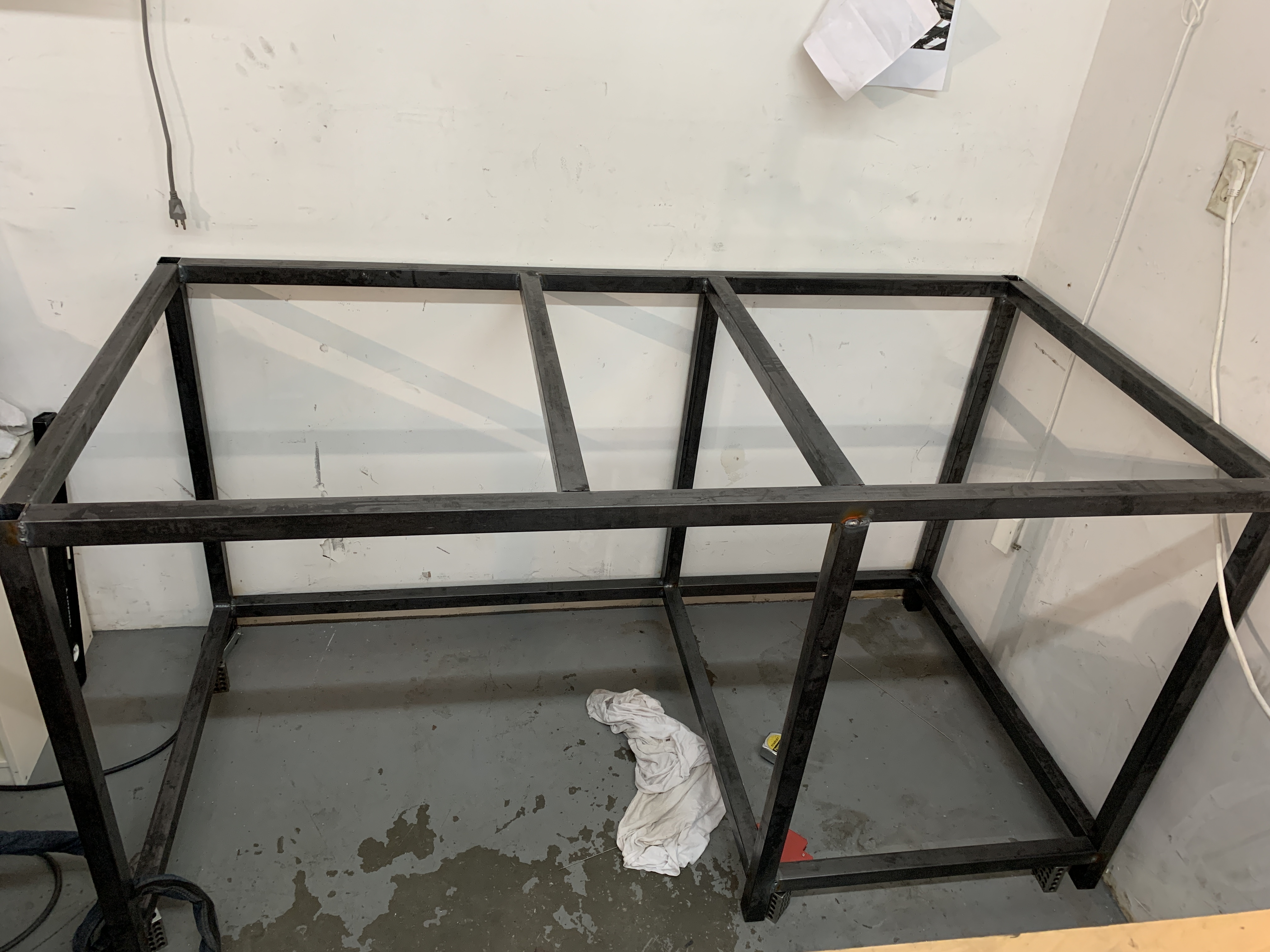
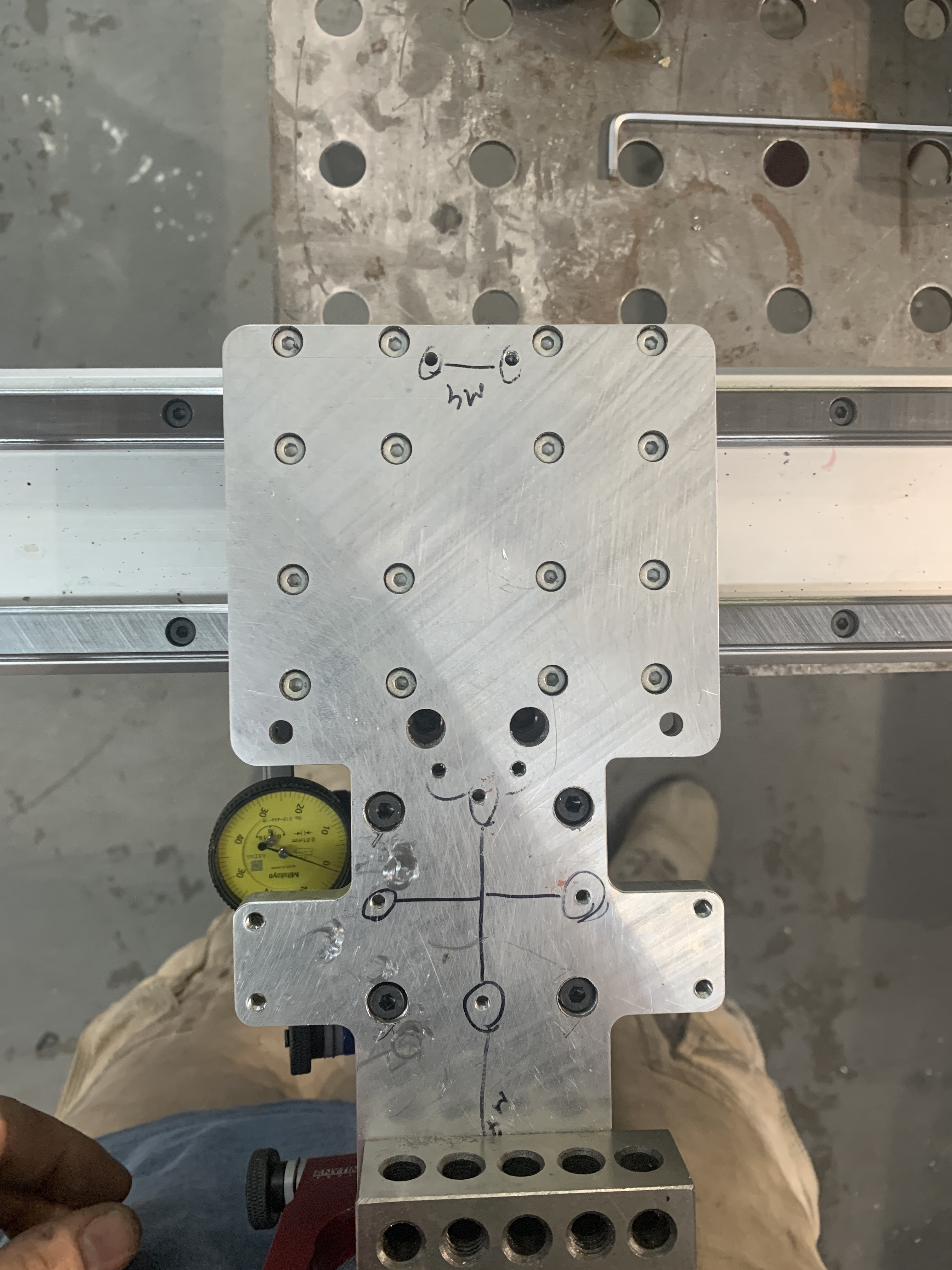
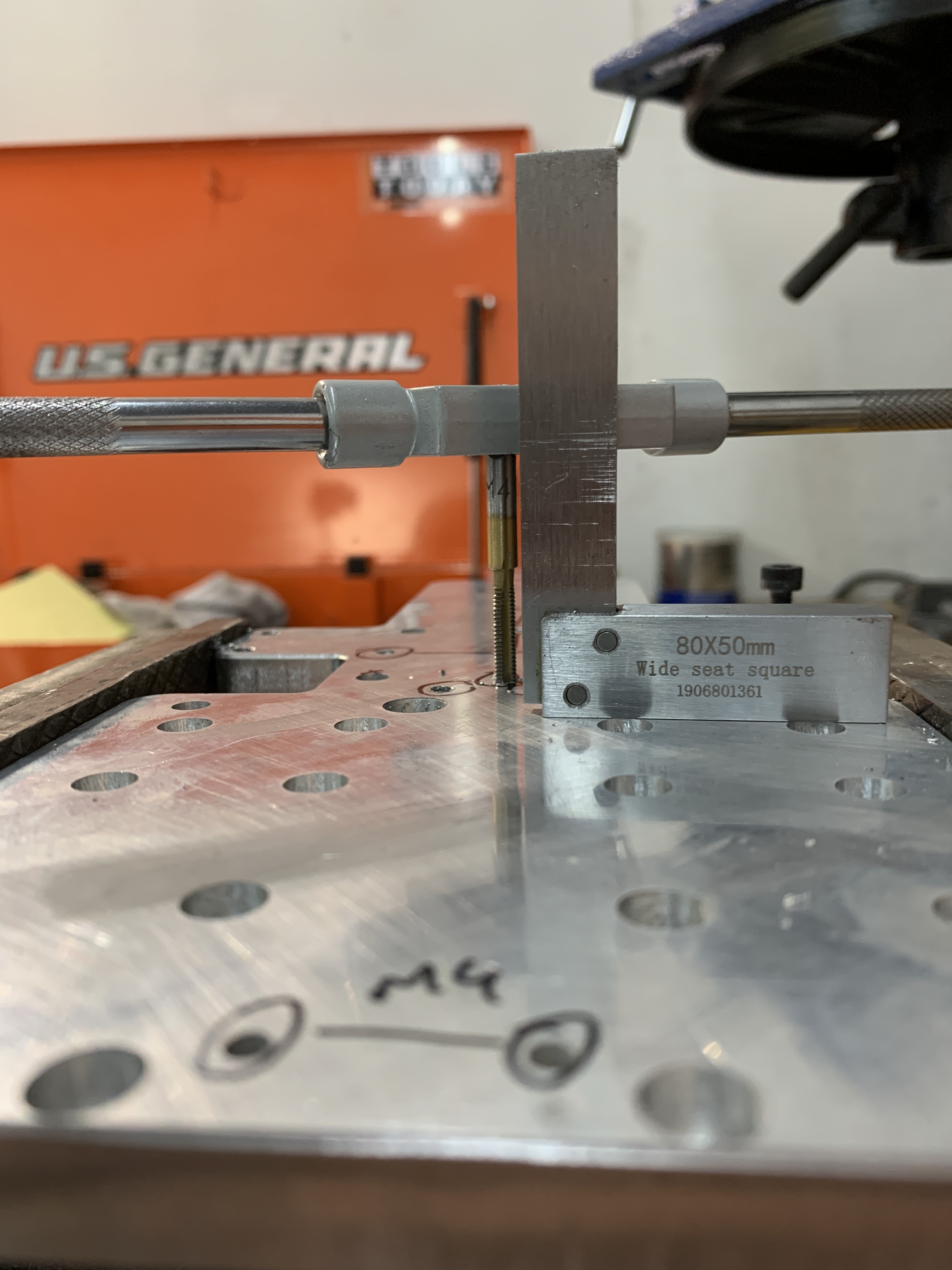
A new semi-enclosure was built. It is a simple metal frame with wood top. I placed a 48"x28" granit scrap from a locate kitchen maker under the shapeoko and removed the leveling feet. The frame is directly on the granite. Then I fixed my ATP-5 1/2" plate. Bought the plate and did my own holes ($190 I believe, which I find pretty good). I have a slight bend on the right side. I am within 0.05mm all over the left side of the work area, but then climbs 0.1mm on the right. Hoever, with the new fixture plate and mini vise in the middle, I am flat and square all around the fixture within 0.03mm. I am very happy for now
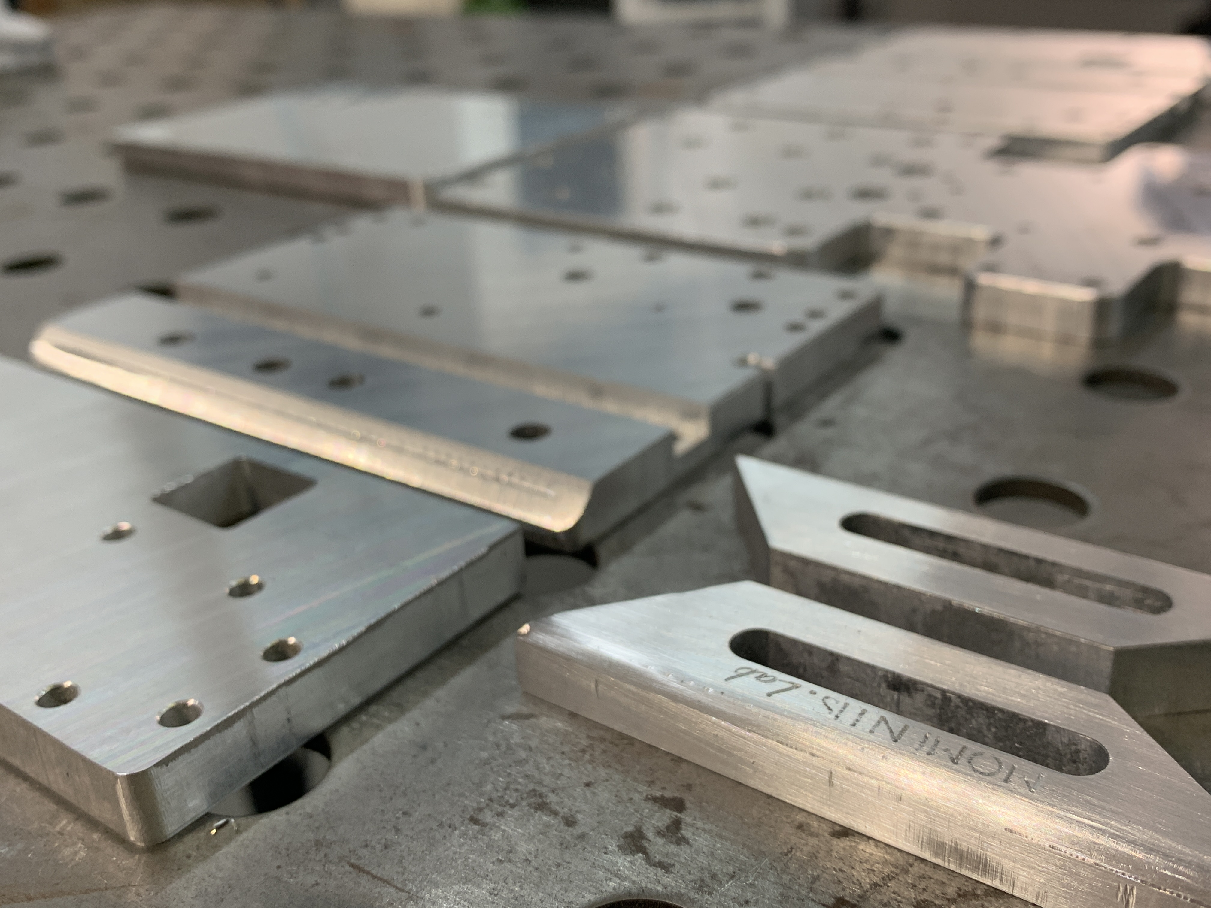
Now I’ll let the pictures speak. Heard they do it best.

Peace 
Dylan