WillAdams
January 25, 2021, 7:52pm
6
Things to start with:
machine level and all the parts square to each other and plumb?
Have you trammed your working area? I’d suggest adding a spoilboard and surfacing that:
Finally taking the time to revisit this with other machine sizes.
For a Shapeoko 3 the rapid coordinate positions are (assuming one has set the origin at the SW rapid position point):
NW = 0, 350
N = 200, 350
NE = 400, 350
W = 0, 215
C = 200, 215
E = 400, 215
SW = 0,0
S = 200, 0
SE = 400, 0
which yields:
[image]
It is possible to move 5mm to the left along X on a Z-Plus machine, and 65mm towards the front of the machine, and the Southernmost Rapid Position Points are align…
For the actual cut you didn’t have geometry assigned:
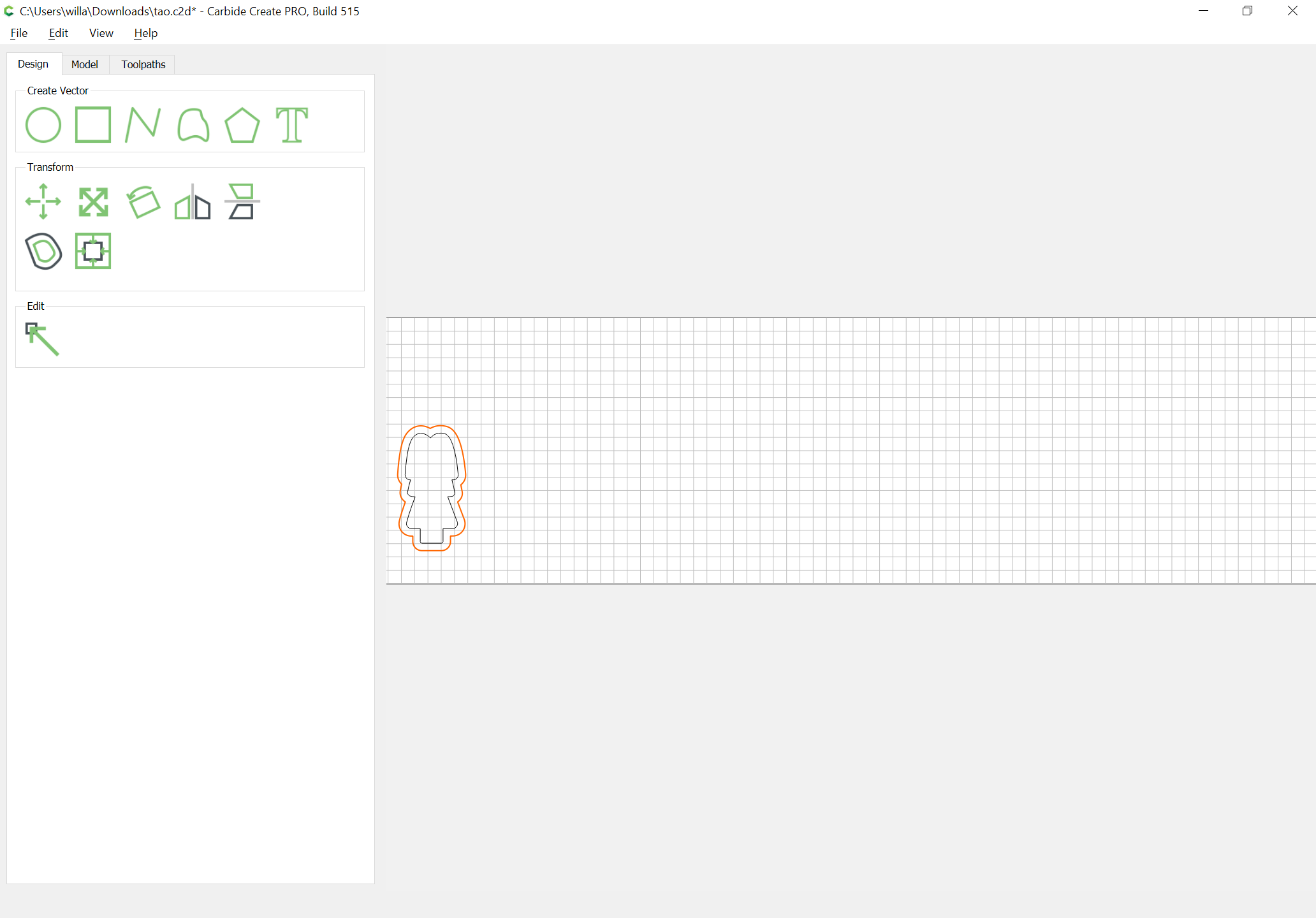
and you are cutting out a simple outer profile / contour — this results in 100% tooling engagement and can be difficult for the machine to do. Best practice is to add geometry around things and cut as a pocket:
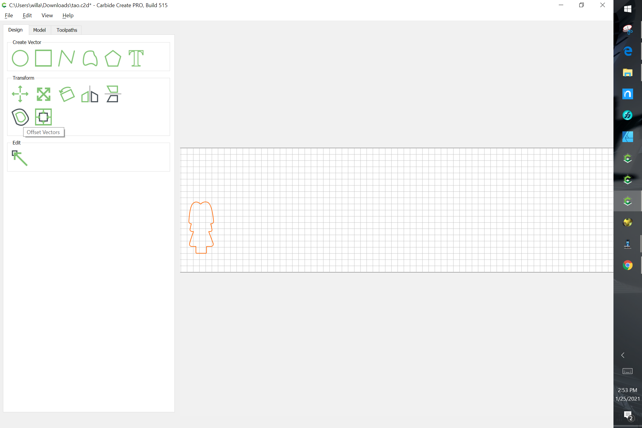
One technique which is often suggested to avoid slotting is to add geometry around a part which one wishes to cut out and cut as a pocket down to tab depth — here’s one technique for that.
In this case, the project is a bevel gauge which will be cut out of 0.0625" (~1.5mm) thick aluminum:
[bevelgauge]
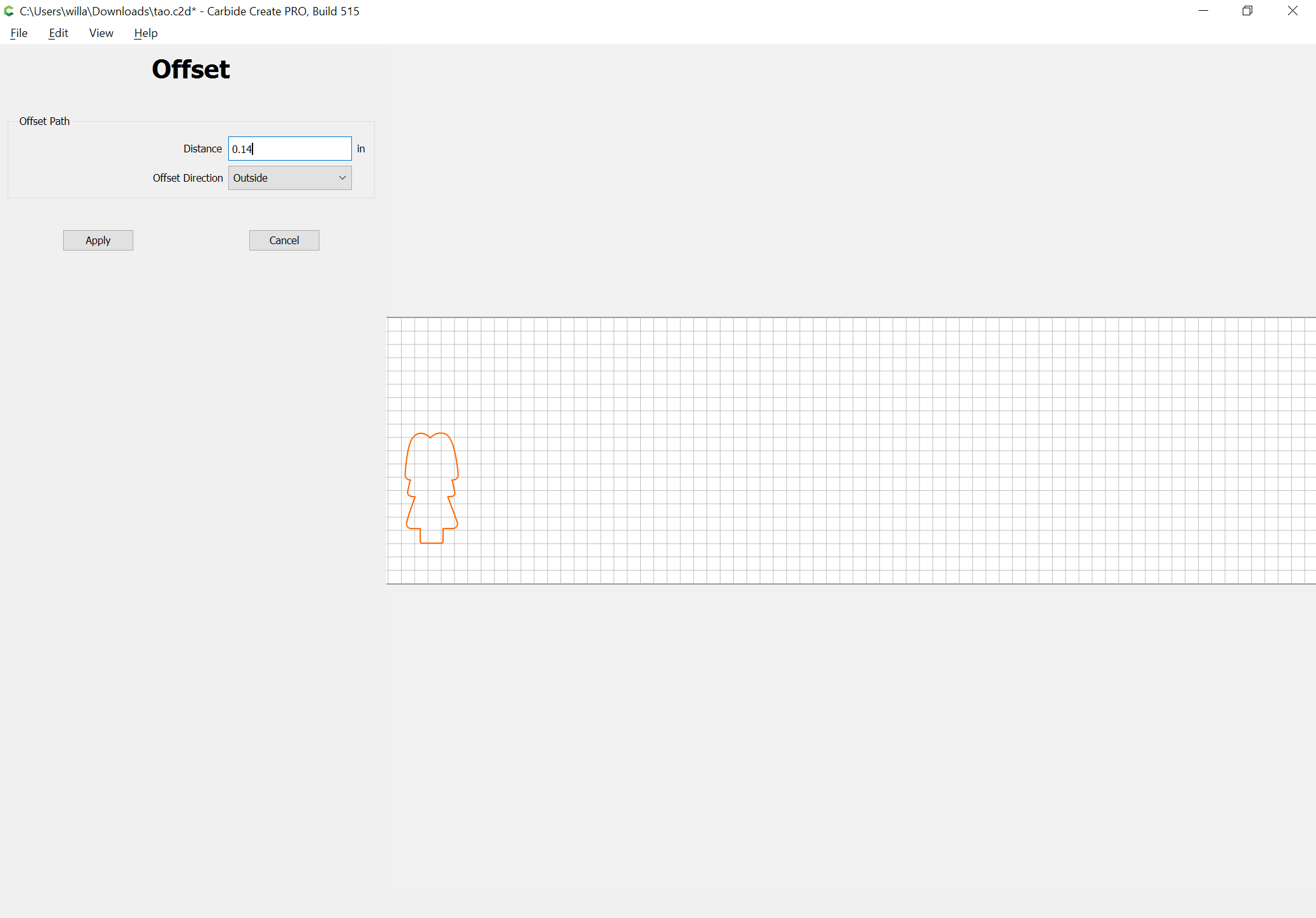
Due to the narrowness of the angles, an 0.03125" endmill has to be used, so after importing and scaling the file (we will be cutting out one which is 3") we select the perimeter and offset it tw…
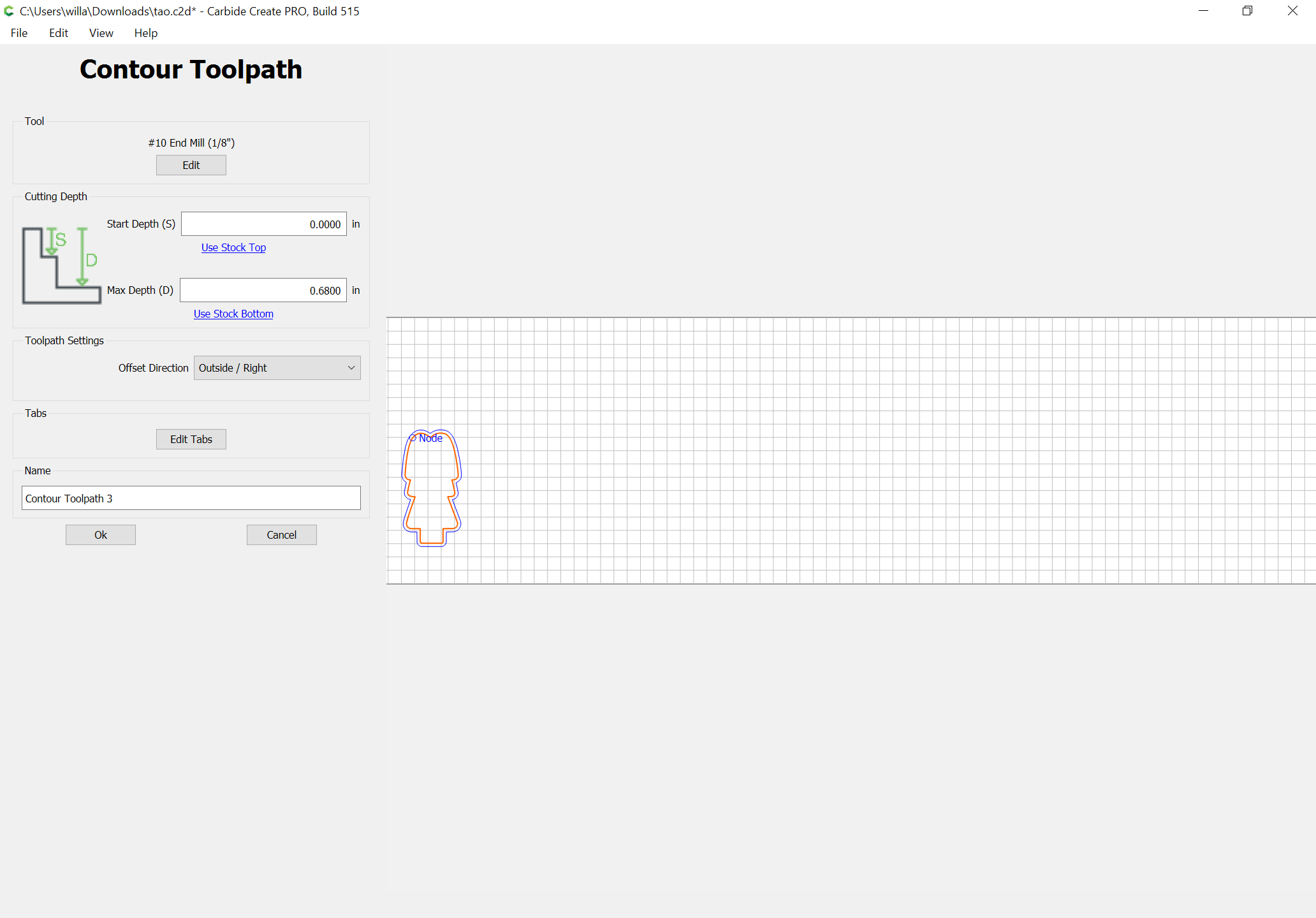
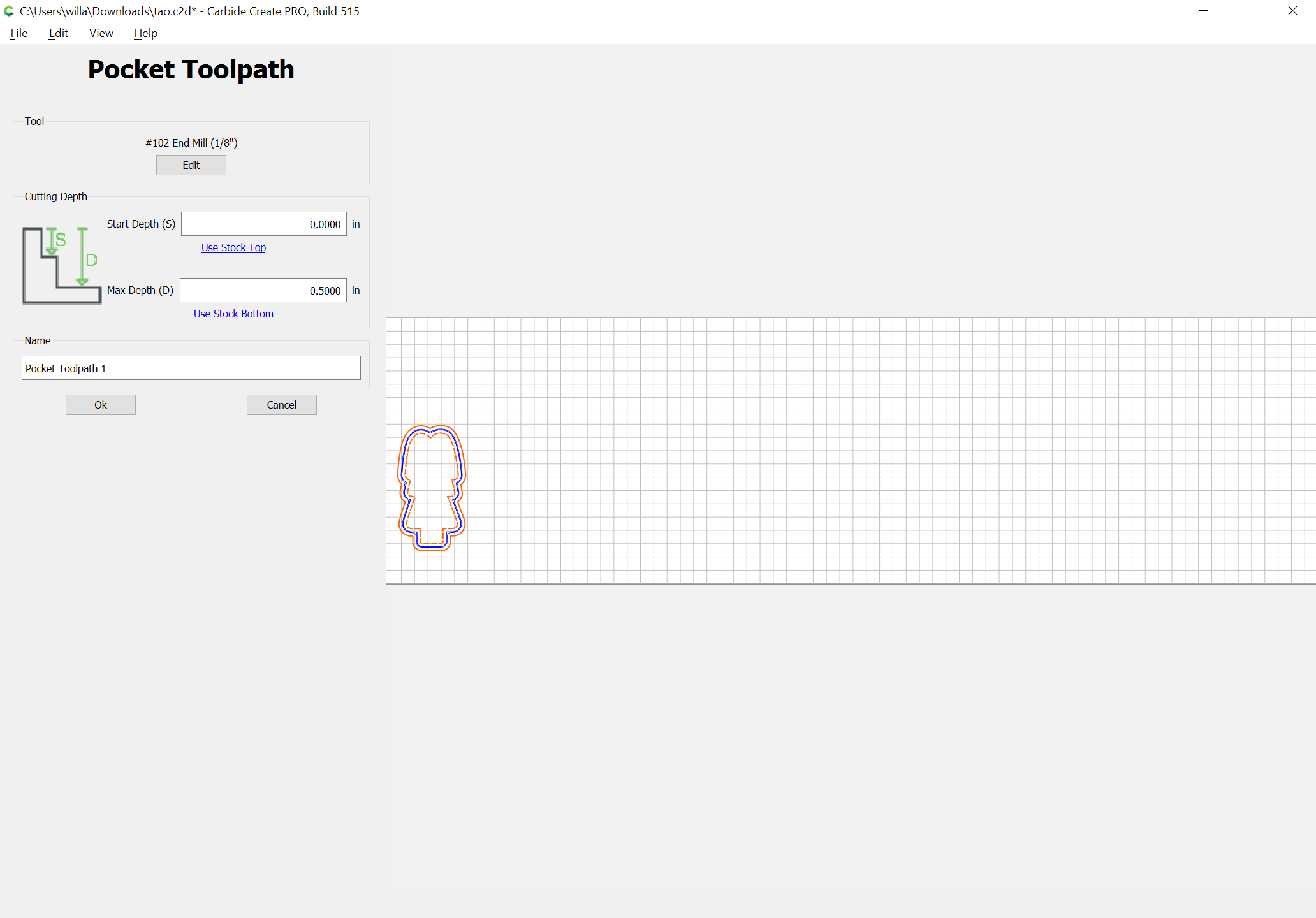
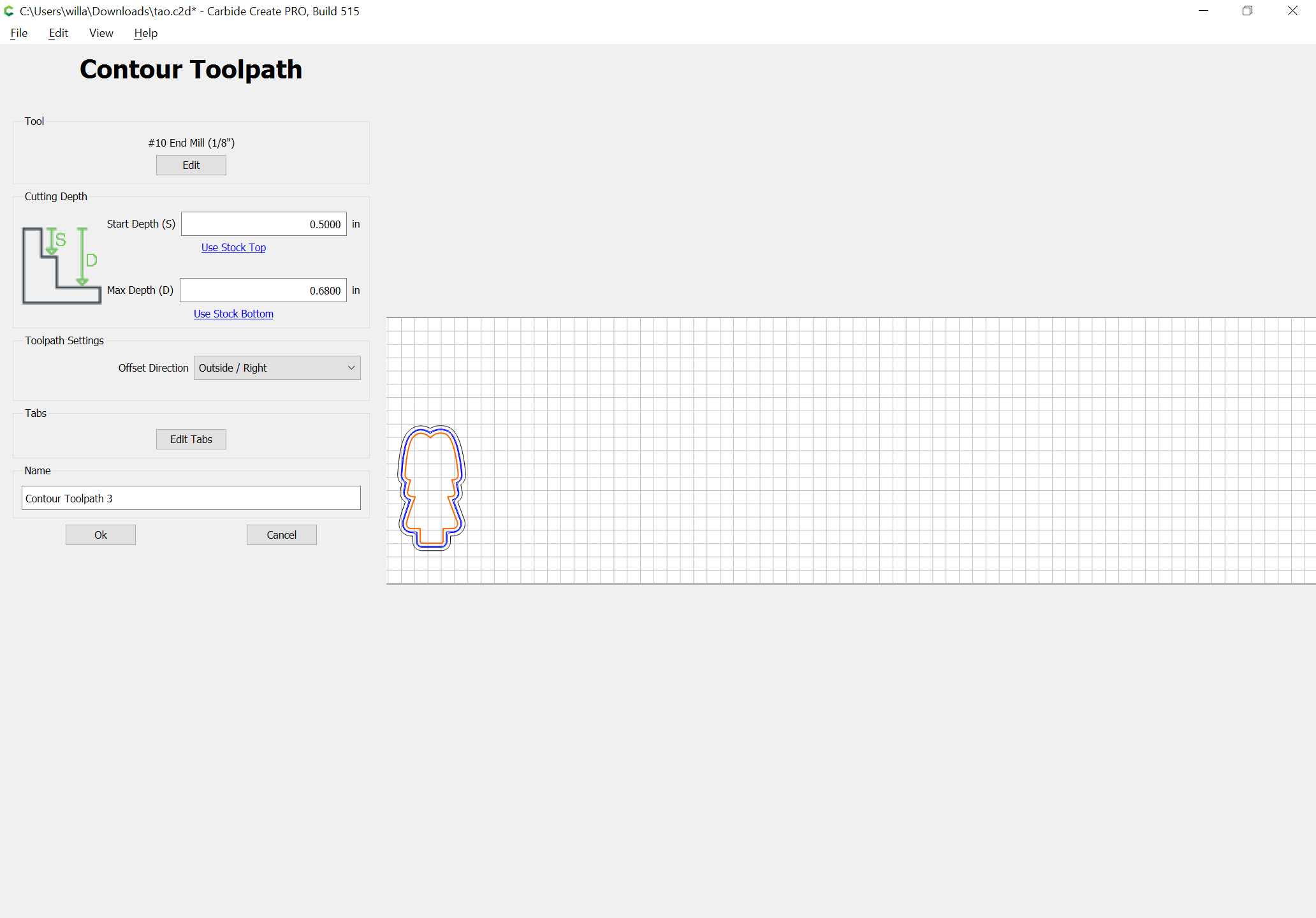
For your charming doll:
(assuming you wish to use a 1/8" endmill)
then modify the profile toolpath to start at the bottom of the pocket, and if desired have tabs:
Have you considered placing the image of the painted doll in the background and then drawing in all the features so that they could be cut as a V engraving so as to guide painting?
1 Like