Finally taking the time to revisit this with other machine sizes.
For a Shapeoko 3 the rapid coordinate positions are (assuming one has set the origin at the SW rapid position point):
| NW = 0, 350 | N = 200, 350 | NE = 400, 350 |
| W = 0, 215 | C = 200, 215 | E = 400, 215 |
| SW = 0,0 | S = 200, 0 | SE = 400, 0 |
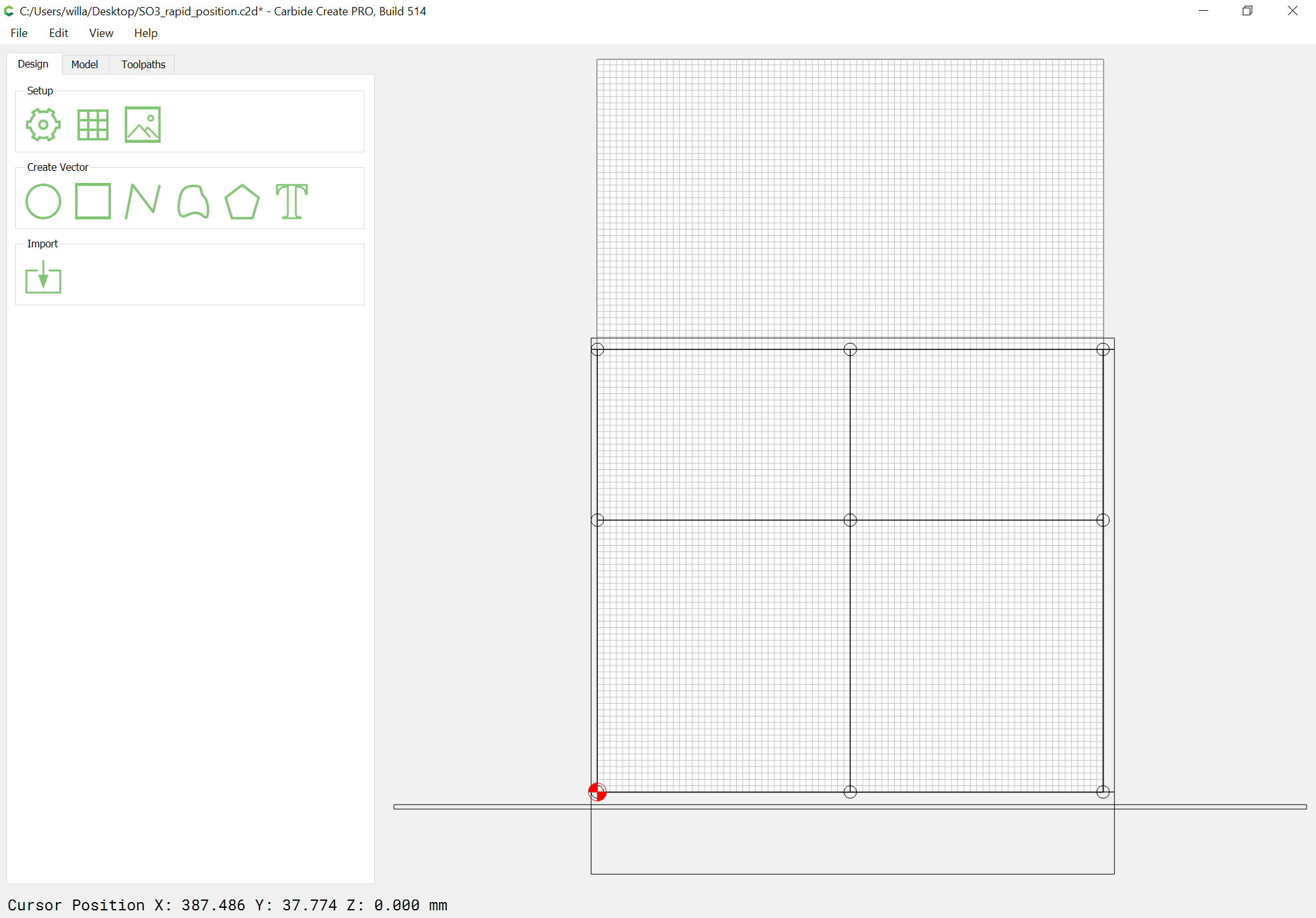
which yields:

It is possible to move 5mm to the left along X on a Z-Plus machine, and 65mm towards the front of the machine, and the Southernmost Rapid Position Points are aligned ~3mm in front of the front edge of the MDF on a machine which was not calibrated for belt stretch.
From the NE position it is possible to move 9mm right and 9mm to the rear.
The rear edge of the front edge plate is ~10mm from that front edge, which is ~3.5mm thick and 722mm wide.
Drawing in that we get:
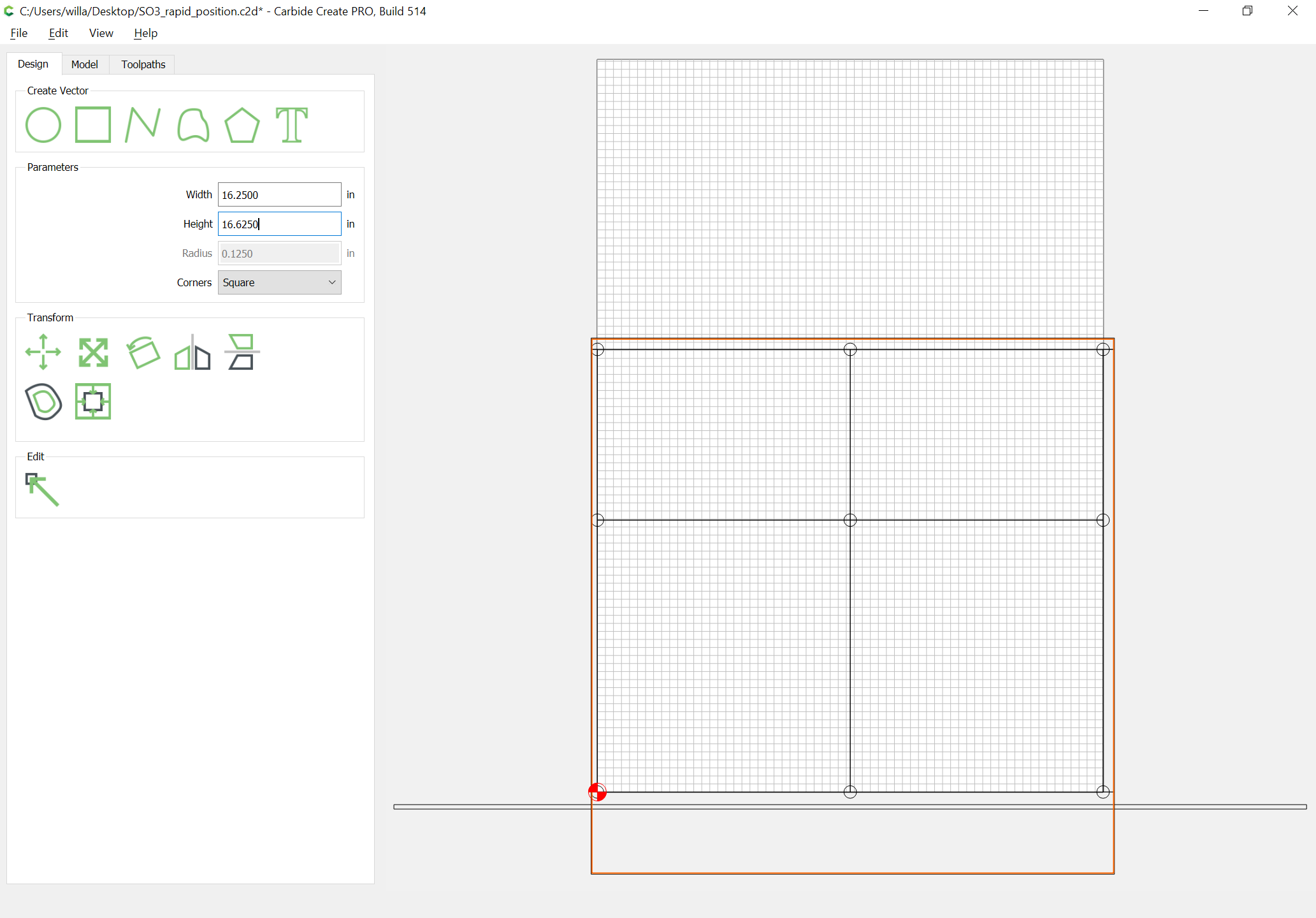
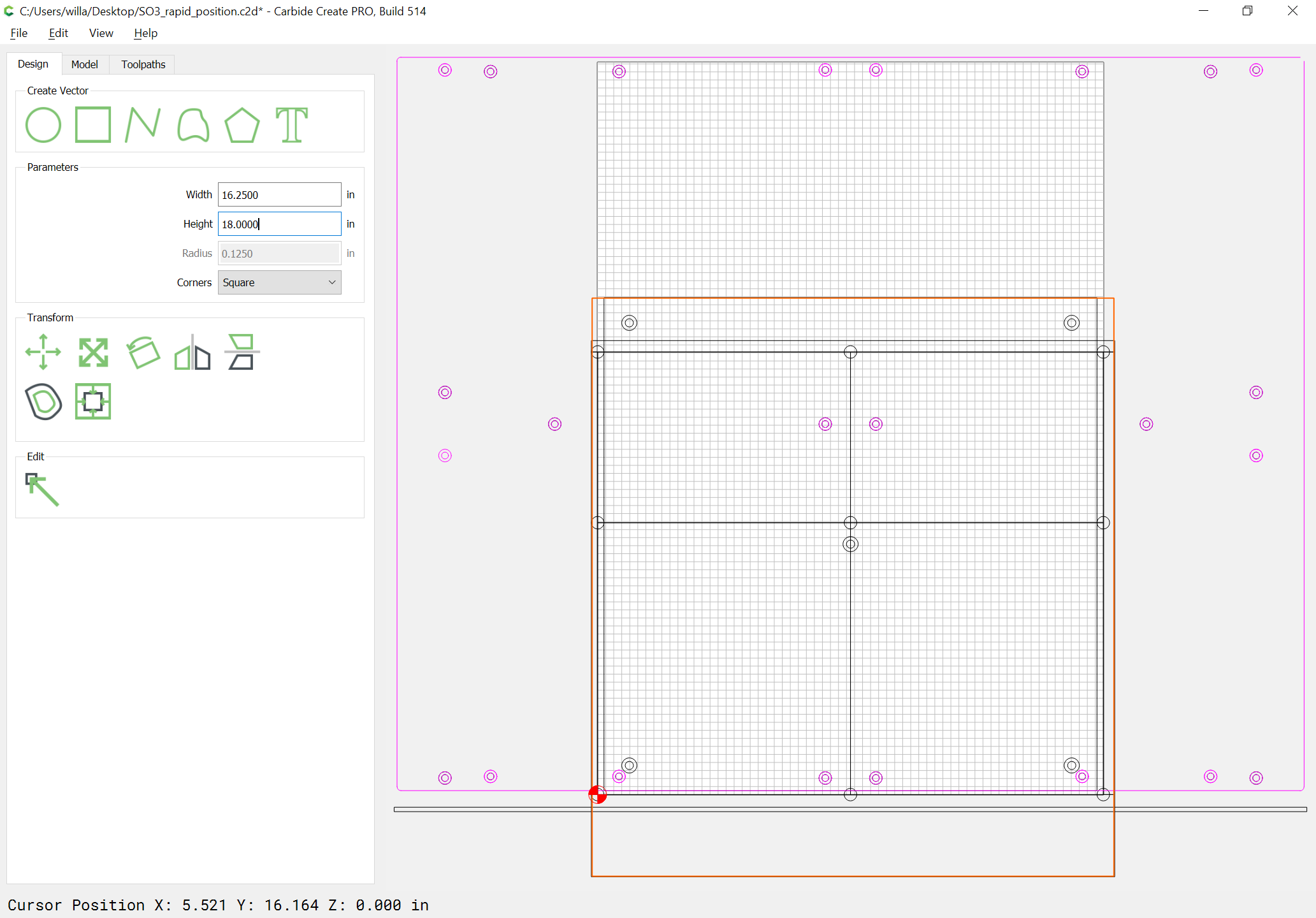
and we have a possible cutting area of 414 x 424mm:
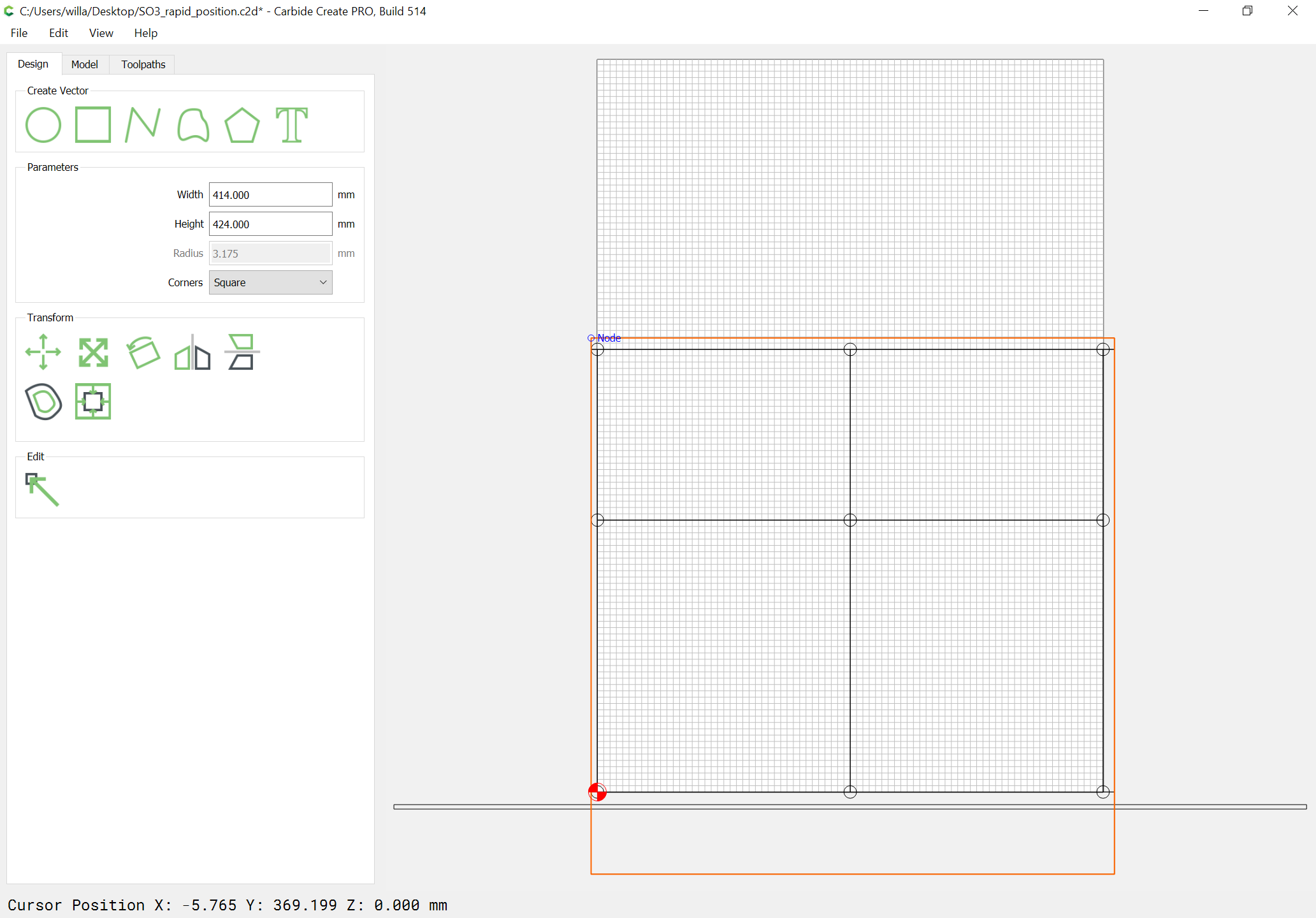
(plus the diameter of the endmill used)
which is a bit more than 16.25" wide, and 16.625" deep (switching to Imperial 'cause it will make life a bit easier for me in cutting it out, and I figure the slight reduction will make any belt stretch issues easier to deal with).
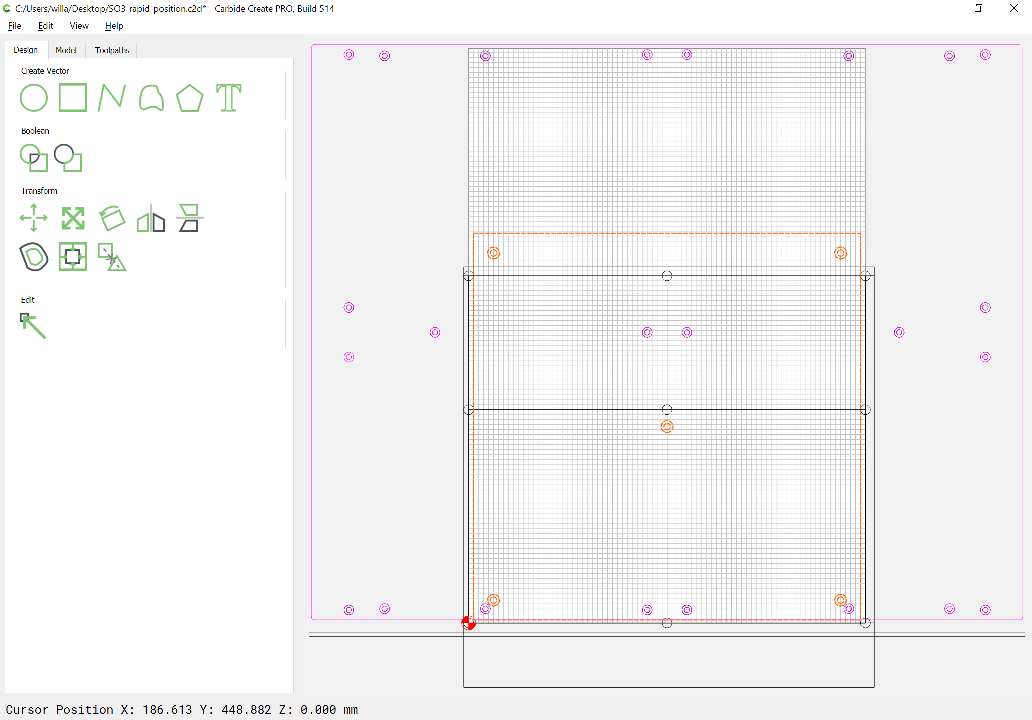
Then, for reference we import a version of the SO3 wasteboard file so that we can see where all the hardware is relative to things:
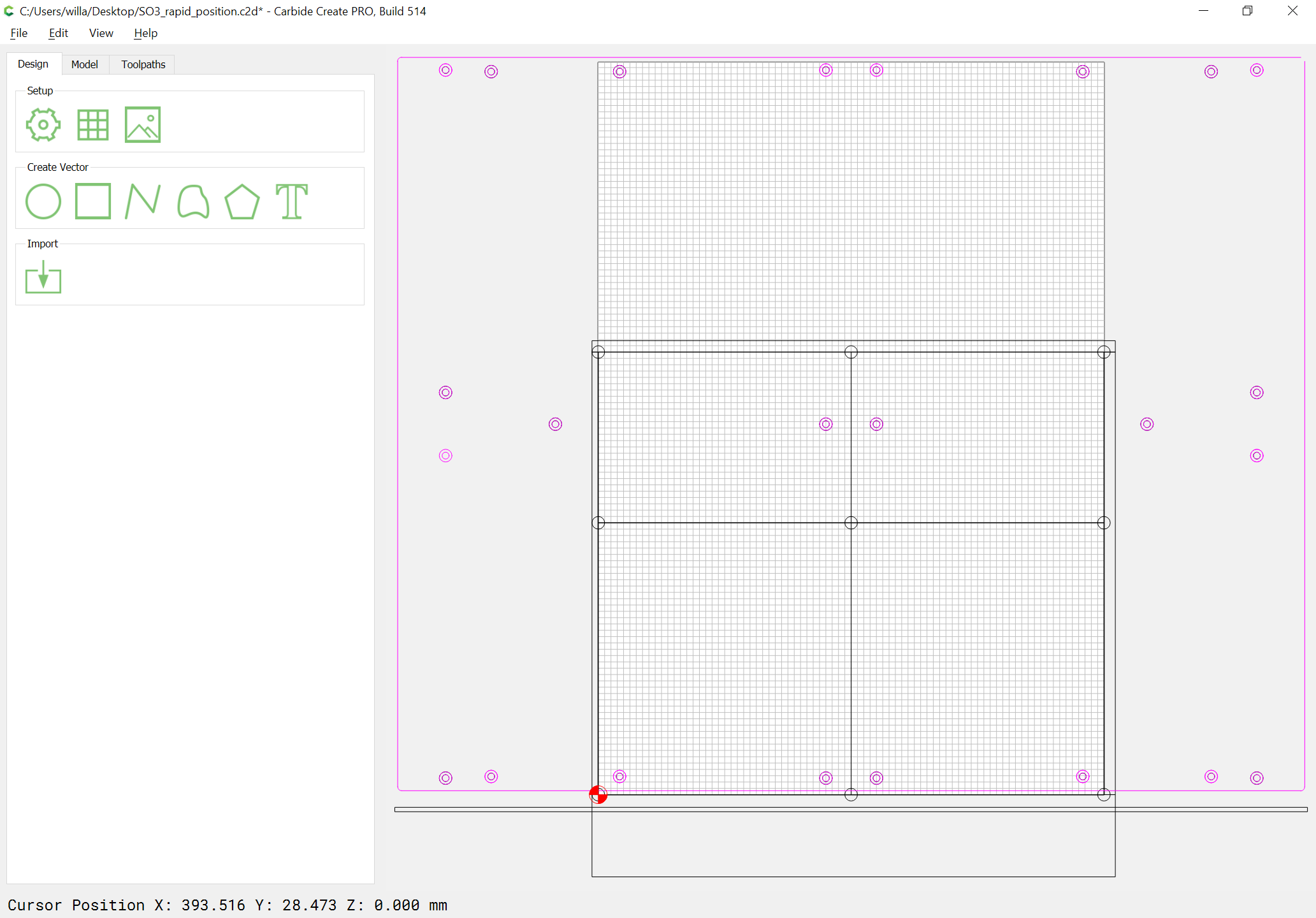
(note that the origin is set at the SW rapid position point)
and lastly, draw up a mounting system for fixtures which @Luke suggested:
which then requires that the stock being cut for the middle layer threaded insert board be slightly extended:
(the previous dimensions will be used for the spoilboard)
In case anyone wants the file (updated per below): SO3_rapid_position.c2d (368.7 KB)