Hi everybody.
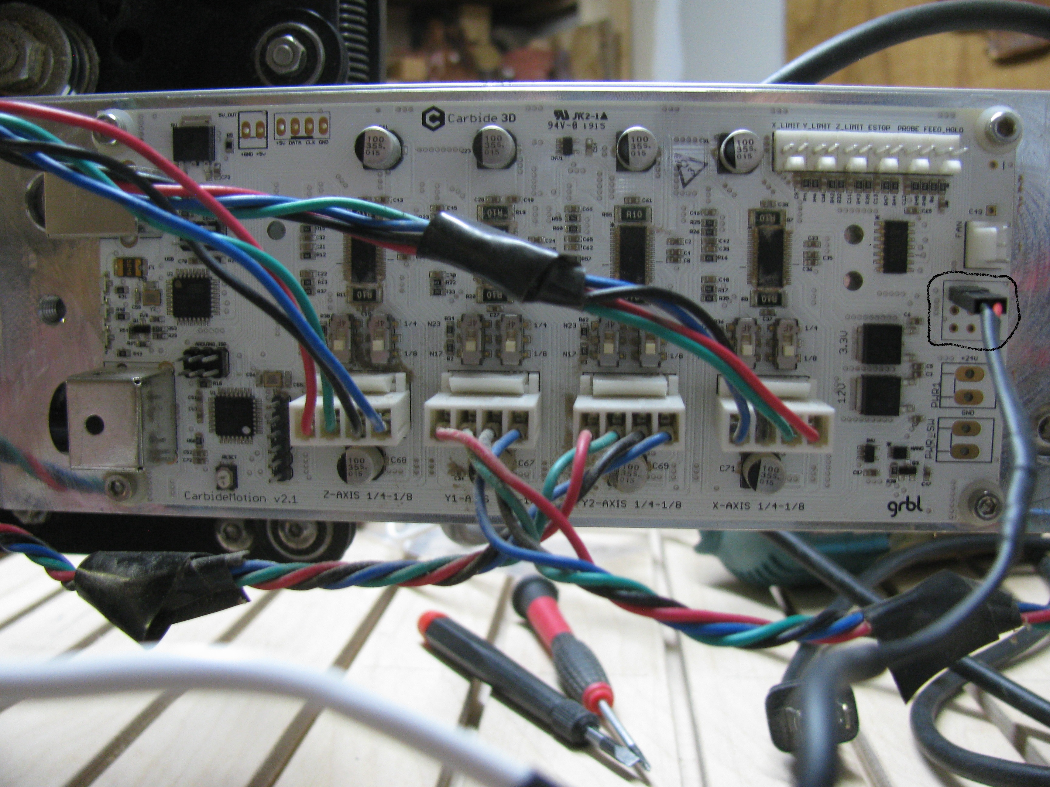
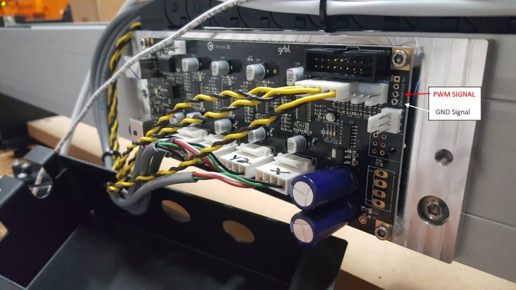
I am trying to hook up the Jtech laser to my Shapeoko 3. I found some video and tutorials on line but I just want be sure I do the right thing. The tutorials shows a different Grbl board than mine. So I am not quite sure if I plugged the signal cable from carbide board to the laser driver in the right spot. I attached two pictures of my board and where I plugged in the wire and one picture from the tutorials!
PS: first picture is my board.
Without ever having tried to hook up a laser, I’m going to say no.
Take a look at this.
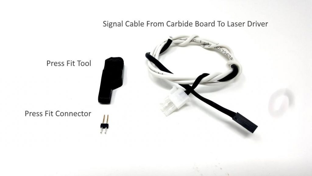
Thank you, no it looks like you are right.I can not see any other holes for that small press fit connector that I have for the signal cable!
Got any electronics experience? Looks like you’ll be soldering some pin headers and modifying the cable.
No, I am a lifetime woodworker and no again, I have not modified anythingt, it is all factory original! I tried to follow the instructions from what I was able to find online, but the layout of the board does not match my board. Since my board as shown above is different from the other board - I can’t figure out where to plug it in.
Thanks
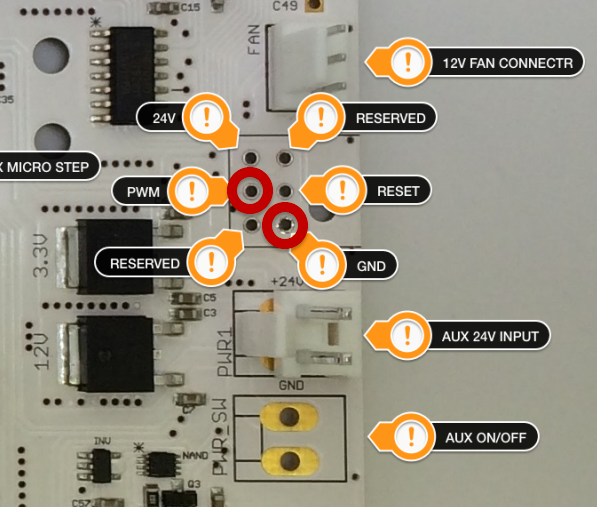
As I recall PWM on your board is middle right, not top right. There is a board layout for the original boards either on the Shapeoko Forum or wiki.
@franazzo Did you click the link in my original post? It shows the ones you need to connect. Unfortunately, they are not next to each other as on the newer boards. You’ll have to solder headers to the correct holes on the board or get press fit connectors that will work. You’ll also have to modify the connector on the cable to connect to those pins. Got anyone with soldering experience you could ask for help?
You could also contact jtech and see if they’ll send you an appropriate connection solution.


@franazzo Please don’t try to use it as you have it connected.
1 Like
Take a look at the link Neil provided, click on ‘this’ link in his first post, I passed over it as well, it’s late and don’t want to tax my brain too hard. If you look at the board layout he references GND is bottom right, PWM is Middle left. You can either solder wires directly to board or cut your header in two with diagonal cutters. If you have a Frye’s or MicroCenter near you they sell header pins and test jumpers you could use also if you don’t want to modify the J-Tech cabling.
2 Likes
Hi -Thanks very much for your response. Yes, I did check your post and I noticed that the set up that they sent me is not the right one and I will have to split the wires to get the right spots. I will get in touch with JTech and see what they have to say. Slowly with the help you have given me, I will probably be able to solve the problem. I will post an update of my progress within the next few days. If I have to, I can do some fine soldering.
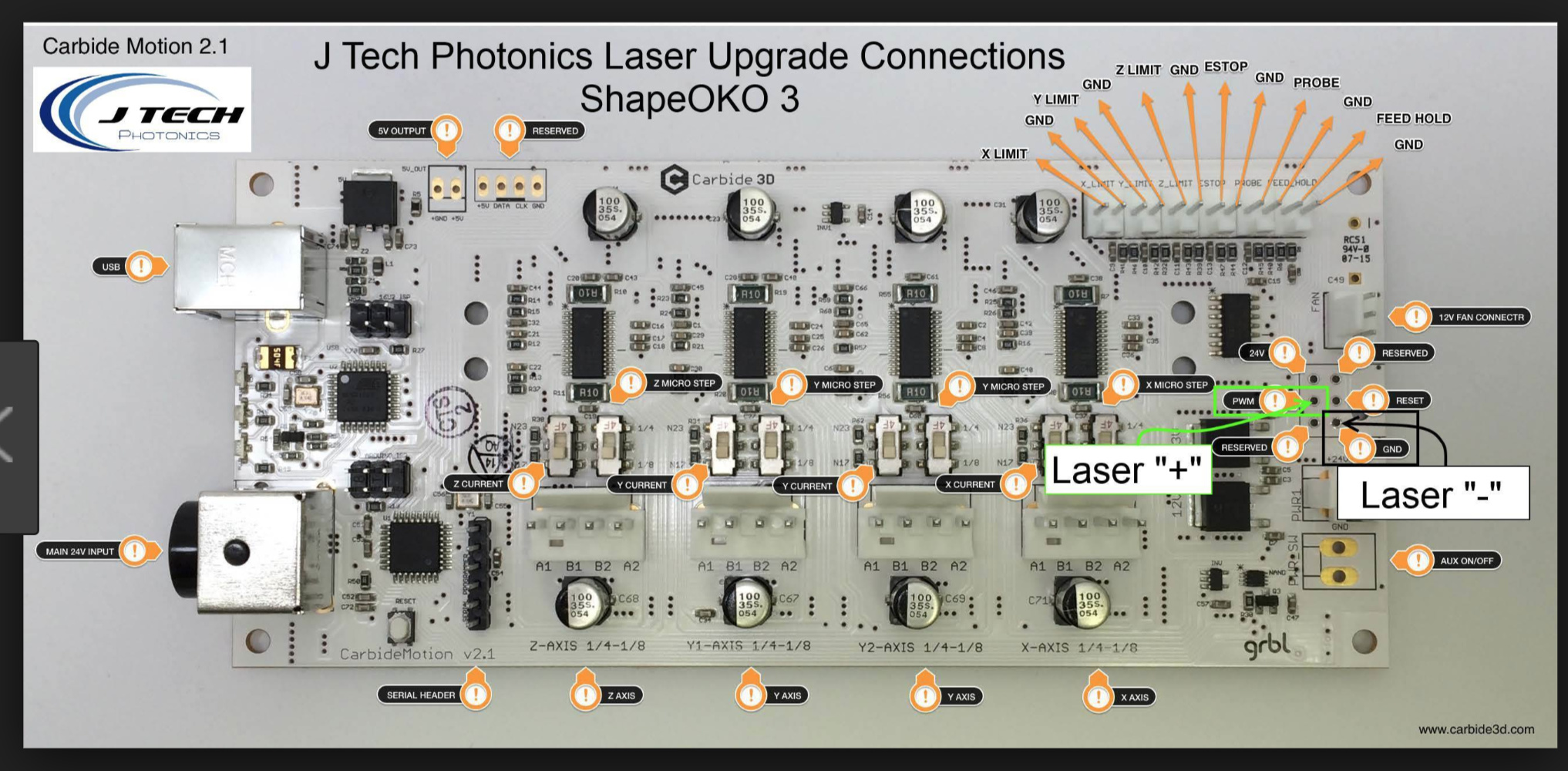
Hi - Thanks again for the pic and your help. The setup which JTech sent me is not quite right, so I have to split the wires and probably solder the wires into those tiny holes. After I split the wires, does it make a difference as to which wire goes into the PWM hole and which one goes into the GND? I will post again in the next few days with an update of my progress. I appreciate everyone’s assistance !
Thank you Rich, I was wondering about the + and -.
Hi Rich -Sorry to bother you again, however I would really like to know if it makes a difference where the Press Fit Connector goes. I don;t know it it makes a difference where the plus and minus goes? Is it switchable or not? Because the setup I got from JTech doesn’t specifiy this. Both pins are the same. ?
I believe the Press Fit connector only fits on V2.4 (there are 4 versions) boards, and since you have an older board, I wouldn’t use it. You may need to cut the connector off and just solder the wires directly onto the board (PWM and GND) at the location outlined in the JTech Photo.
Having said that, I recommend that you contact JTech for detail instructions for the older V2.1 Board.
Sorry I forgot to address your +/- question.
They are NOT switchable. GND = - (Negative) and PWN + (Positive) is 0V to 5V.
Your Laser controller is marked as to where these (+/-) wires go.

1 Like
Thank you Rich, and have a Happy New Year!
Hi Everyone! And Happy New Year!
I am back again  I just have a short question before I can start working on my laser again. I have all of the wires hooked up according to the sketches and when I turned it on, NOTHING happened !! Now, my question is “Does the software have to be installed before the driver unit is working?” I made sure that I had the color co ordination right and I double checked everything and it looks okay. So I am hoping to find an answer as to why it doesn’t turn on; there are no lights - just nothing!? Thanks for any help pointing me in the right direction, again!


List item
did you press the reset button after plugging it up?