Yes it’s shareable. I also use it at work for a wire EDM and was able to make a small change years ago. That post was quite different from a milling post so I was able to make the changes. Now anytime I make any changes it gives an error. I’m sure there is a manual somewhere, but I wouldn’t know where to find it. Here is the text in the post
************************** SYSTEM VARIABLES ****************************
POSTNAME : YCM XV MXP200I 01/12/06
XSTART : 0
YSTART : 0
ZSTART : 0
UPPERCASECOMMENTS : 1
TOOLCHANGE_HIGHZ : 999.9999
MACHINETOLERANCE : 0.0001
**************************** MACHINE MODES *******************************
COORDINATEMODE : ABSOLUTE
MEASUREMENTMODE : INCH
CIRCLEMODE : FULLCIRCLE
CENTERMODE : INCREMENTFROMSTART
RAPIDMODE : PLUNGE
WORKPLANEMODE : XYPLANE
RETURNPLANEMODE : RRETURN
MILLRETRACTMODE : MILLPLUNGE
LENGTHCOMPOUTMODE : TOOLCHANGEONLY
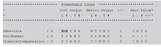
************************* FORMATABLE CODES *******************************
PROGRAMNUMBER : O Y 4 N N 0 Y 4 N N 0 0 1 N 0 0
SEQUENCENUMBER : N Y 4 N N 0 Y 4 N N 0 0 1 N 0 0
XABSOLUTE : X 1 4 Y 1 4 1 5 Y 1 3 1 1 N 0 0
YABSOLUTE : Y 1 4 Y 1 4 1 5 Y 1 3 1 1 N 0 0
ZABSOLUTE : Z 1 4 Y 1 4 1 5 Y 1 3 1 1 N 0 0
CIRCLERADIUS : R 1 4 Y 1 4 1 5 Y 1 3 1 1 N 0 0
XCENTERABSOLUTE : I 1 4 Y 1 4 1 5 Y 1 3 1 1 N 0 0
YCENTERABSOLUTE : J 1 4 Y 1 4 1 5 Y 1 3 1 1 N 0 0
ZCENTERABSOLUTE : K 1 4 Y 1 4 1 5 Y 1 3 1 1 N 0 0
FEEDRATE : F 1 3 Y 1 2 1 4 N 1 0 0 1 N 0 0
RPLANE : R_ 1 4 Y 1 4 1 5 Y 1 3 1 1 N 0 0
DWELLTIME : P 1 5 Y 1 3 1 5 Y 1 3 0 1 N 0 0
PECK : Q 1 4 Y 1 4 1 5 Y 1 3 1 1 N 0 0
INITPECKINCREMENT : I_ 1 4 Y 1 4 1 5 Y 1 3 1 1 N 0 0
POCKETRADIUS : I__ 1 4 Y 1 4 1 5 Y 1 3 1 1 N 0 0
POCKETDEPTH : Z__ 1 4 Y 1 4 1 5 Y 1 3 1 1 N 0 0
MISCFORMAT1 : L 1 2 N N 0 1 5 Y 1 3 1 1 N 0 0
STEP : Q_ 1 4 Y 1 4 1 5 Y 1 3 1 1 N 0 0
MISCFORMAT2 : J_ 1 4 Y 1 4 1 5 Y 1 3 1 1 N 0 0
RETRACTAMOUNT : K_ 1 4 Y 1 4 1 5 Y 1 3 1 1 N 0 0
SPINDLESPEED : S N 4 N N 0 N 4 N N 0 0 1 N 0 0
TOOLNUMBER : T Y 2 N N 0 Y 2 N N 0 0 1 N 0 0
DIAMETERCOMPENSATION : D Y 2 N N 0 Y 2 N N 0 0 1 N 0 0
LENGTHCOMPENSATION : H Y 2 N N 0 Y 2 N N 0 0 1 N 0 0
MISCFORMAT3 : G Y 2 N N 0 Y 2 N N 0 0 - - - -
MISCFORMAT4 : X_ 1 4 Y 1 4 1 5 Y 1 3 1 1 N 0 0
MISCFORMAT5 : Y_ 1 4 Y 1 4 1 5 Y 1 3 1 1 N 0 0
MISCFORMAT6 : Z_ 1 4 Y 1 4 1 5 Y 1 3 1 1 N 0 0
************************* SYMBOLIC CODES ***************************
MOTIONRAPID : G00
MOTIONLINEAR : G01
MOTIONCW : G02
MOTIONCCW : G03
DWELL : G04
SPIRALCW : G12
SPIRALCCW : G13
XYPLANE : G17
ZXPLANE : G18
YZPLANE : G19
INCH : G20
METRIC : G21
ZERORETURN : G28
COMPENSATIONOFF : G40
COMPENSATIONLEFT : G41
COMPENSATIONRIGHT : G42
COMPENSATIONPLUS : G43
COMPENSATIONMINUS : G44
LENGTHCANCEL : G49
WORKSYSTEM1 : G54
WORKSYSTEM2 : G55
WORKSYSTEM3 : G56
WORKSYSTEM4 : G57
WORKSYSTEM5 : G58
WORKSYSTEM6 : G59
INZONEPOSITIONING : G64
CANCEL : G80
DRILL1 : G81
DRILL2 : G82
PECK1 : G83
PECK2 : G73
TAP1 : G84
TAP2 : G74
BORE1 : G85
BORE2 : G86
BORE3 : G76
BORE4 : G89
ABSOLUTE : G90
INCREMENTAL : G91
SETORIGIN : G92
IRETURN : G98
RRETURN : G99
PERCENTSIGN : %
PROGRAMSTOP : M00
OPTIONALSTOP : M01
REWINDSTOP : M02
SPINDLECW : M03
SPINDLECCW : M04
SPINDLEOFF : M05
TOOLCHANGE : M06
COOLANTON : M08
COOLANTOFF : M09
ENDPROGRAM : M30
MISCSYMBOLICCODE1 : Y0_Z0
**************************** EXAMPLES ********************************
VARIABLE : StartPointFlag Test Tap
EX_STARTPOINT : IF (StartPointFlag)
: G00 G90 WORKSYSTEMCODE* X Y IF(Tap<>(4))S SPINDLEDIRECTION ENDIf
: G43* H* Z_(initialclearance) M08 IF(nexttool>0) T(nexttool) ELSE T(firsttool) ENDIF
: IF (nextdim(3)<>initialclearance) Z ELSE NCOUTPUTOFF Z NCOUTPUTON ENDIF
: StartPointFlag=(0)
: ENDIF
EX_RAPID : IF (StartPointFlag) EXITEXAMPLE ENDIF
: G00 X Y Z
EX_LINEAR : Test=(nextclfile(631))
: G01 X Y Z F
EX_CIRCLE : IF (xpresent = xlast && ypresent = ylast)
: G17 CIRCLEDIRECTION X Y Z I* J* F
: ELSE
: G17 CIRCLEDIRECTION X Y Z R* F
: ENDIF
EX_CIRCLEZX : IF (xpresent = xlast && ypresent = ylast)
: G18 CIRCLEDIRECTION X* Z* I* K*
: ELSE
: G18 CIRCLEDIRECTION X* Z* R*
: ENDIF
EX_CIRCLEYZ : IF (xpresent = xlast && ypresent = ylast)
: G19 CIRCLEDIRECTION Y* Z* J* K*
: ELSE
: G19 CIRCLEDIRECTION Y* Z* R*
: ENDIF
EX_COMPENSATION : G01* COMPENSATIONSIDE X Y Z D F M08
EX_COMPENSATIONOFF : G01* G40 X Y Z F
EX_CYCLESTART : COMMENT(1)
EX_TOOLCANCEL : “Z5.0” M09*
: “G91” G28* “Z0” M05*
: M01*
EX_PARK : IF (PARKRETURNCODE = PARKRETURNYZ)
: “G00 G53 Y0 Z0”
: PARKRETURNCODE*
: BLANKLINE
: COMMENT
: BLANKLINE
: G43* H* Z_(initialclearance) M08
: ENDIF
VARIABLE : opnum
EX_STARTCODE : opnum=(0)
: %
: O* PROGRAMNAME
: “(YCM XV.ASC 11/10/06)”
: BLANKLINE
: “( ******* PART SETUP INFO ******* )”
: BLANKLINE
: SETORIGINCOMMENT
: BLANKLINE
: “( ******* TOOL SETUP DATA ******* )”
: BLANKLINE
EX_TOOLDEFINITION : TOOLCHANGECOMMENT
EX_MAINSTART : BLANKLINE
: “( ******** PART PROGRAM ********* )”
EX_FIRSTTOOLCHANGE : BLANKLINE
: N(presenttool) G00* G17* G28* G40* G80* “G91 Z0”
: T* M06* TOOLCHANGECOMMENT(1)
: StartPointFlag=(1)
: Tap=(nextclfile(110))
EX_OTHERTOOLCHANGE : BLANKLINE
: N(presenttool) G00* G17* G28* G40* G80* “G91 Z0”
: T* M06* TOOLCHANGECOMMENT(1)
: StartPointFlag=(1)
: Tap=(nextclfile(110))
EX_LASTTOOLCHANGE : BLANKLINE
: N(presenttool) G00* G17* G28* G40* G80* “G91 Z0”
: T* M06* TOOLCHANGECOMMENT(1)
: StartPointFlag=(1)
: Tap=(nextclfile(110))
EX_ENDCODE : G28* “Y0”
: T*(firsttool) M06*
: G90* M30*
: %
EX_DRILLSTART : COMMENT
: RETURNPLANECODE* DRILLCYCLECODE* X Y Z* R_* F* M08
EX_DRILLBODY : RETURNPLANECODE DRILLCYCLECODE X Y Z R_ M08
EX_DRILLCANCEL : G80*
EX_DRILL2START : COMMENT
: RETURNPLANECODE* DRILLCYCLECODE* X Y Z* R_* F* P* M08
EX_DRILL2BODY : RETURNPLANECODE DRILLCYCLECODE X Y Z R_ F P M08
EX_DRILL2CANCEL : G80*
EX_PECKSTART : COMMENT
: RETURNPLANECODE* PECKCYCLECODE* X Y Z* R_* Q* F* M08
EX_PECKBODY : RETURNPLANECODE PECKCYCLECODE X Y Z R_ Q F M08
EX_PECKCANCEL : G80*
EX_TAPSTART : COMMENT
: “M29” S*
: RETURNPLANECODE* TAPCYCLECODE* X Y Z* R_* F* M08
EX_TAPBODY : RETURNPLANECODE TAPCYCLECODE X Y Z R_ F M08
EX_TAPCANCEL : G80*
EX_BORESTART : COMMENT
: RETURNPLANECODE* BORECYCLECODE* X* Y* Z* R_* P* F* M08
EX_BOREBODY : RETURNPLANECODE BORECYCLECODE X Y Z R_ P F M08
EX_BORECANCEL : G80*
**************************** END EXAMPLES *********************************
I know I have to make the changes in the first tool change area, but every time I change anything I get an error.