Hello,
I just bought a Nomad 3 and am trying to cnc my first project: a challenge coin that I designed as a 3D model. I intend on doing a wood test model, then a brass final piece.
I have used the Meshcam simulation and the result appears very soft ( the letters and details are not sharp). I will be using .125 square mill for roughing and a .032 ballnose endmill for finishing.
Can anyone give me some advice on how to mill the details with sharpness?
Any help would be greatly appreciated!
Hello Vicky - welcome to the community and all that
What are the dimensions of the coin? If it’s about 1" / 25mm then you unfortunately won’t get much detail with the tools you’ve chosen. A ball endmill or a square endmill cannot carve out a sharp acute angle (since they are round).
You would probably be better off treating this as a VCarve-ish project and use a sharp angled VBit (30 degrees or less). This will allow some of the detail to come through. Clearance bits of 2mm and 1mm could be used to clear some of the flat areas prior to the VBit doing its thing.
Thank you for the quick reply!
The coin will be 1.75" x .08 ", so its quite large. As for software, I am using meshcam, as it is the easiest to learn. Carbide create is the only other one that I have. I have a PCB engraver endmill, but I cannot see an option in Meshcam for it.
Can you please give me any recommendations? It it worth it to buy vcarve (it’s pretty pricey!).
I’ve used version 6 of Meshcam only a few times using the license came with my Nomad 883 Pro. You probably need to add a new tool to have the engraver as an option - I’m not 100% sure if it knows how to use it though, but it’s worth a try.
You probably need to get some 30 degree V bits from somewhere rather than use the PCB engraver (Amazon have some cheap ones that come in packs of 10 so you can destroy them during your experimentation).
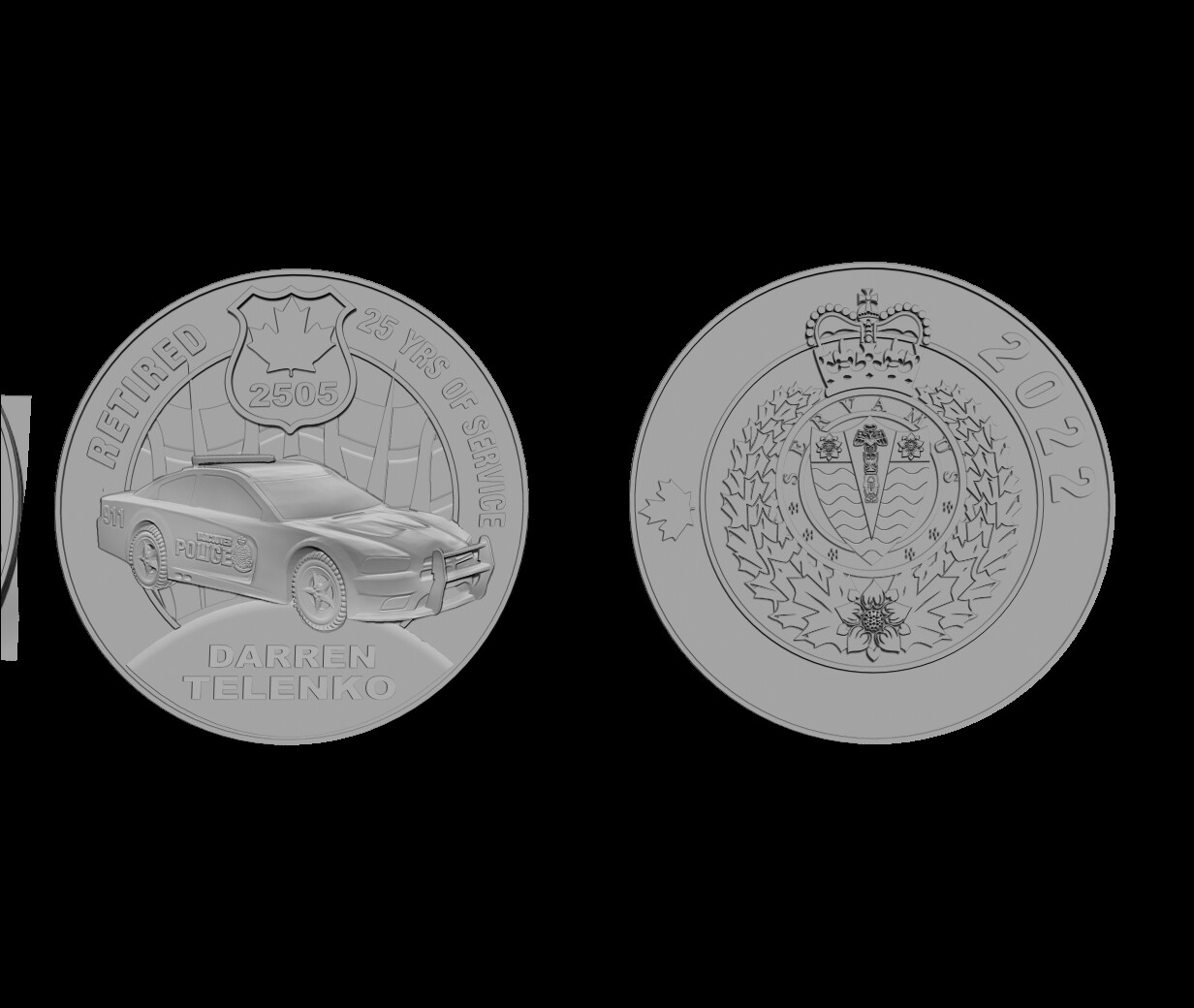
For your design, you have several parts that are really just “2.5D” - the text, badge symbol, the insignia on the reverse of the coin, the officer’s name (… he’s seen some difficult things in his years according to the news).
The only complex 3D shape is the patrol car. Maybe the flower on the insignia too but I can’t see that clearly.
So separating these two elements out might give you a better result.
You could use Carbide Create’s Advanced VCarve to do the 2.5D parts, exported as flat vectors, with a VBit and another small endmill. This should make a reasonably sharply defined cut.
The car is trickier and will probably need a very fine tapered ball mill and Meshcam - or if you can convert it to a greyscale image, you could use a trial of Carbide Create Pro to generate the toolpaths for that and keep the project in the one file.
I use VCarve Desktop and I find it works really well (I would still probably separate the car from the rest), but as you say it is expensive and you probably need to get a hang of things before diving in with your wallet any further.
I’m sure other people will have some other ideas, too.
I believe one of the issue of it looking “soft” is the amount of detail desired vs. the end mill size. For that detail, you are probably going to have to use a smaller end mill. A 0.25mm radius (0.0196" dia tip) tapered ball mill may get you closer to what you want, but you may have to go smaller than that.
As @WillAdams says, Carbide Create Pro doesn’t import STLs. If it did, MeshCAM would be of less value (according to other posts by Will), and there are common people involved in both software products.
So people are stuck with CC Pro using images that are height maps… which practically nobody uses, so you have to use external tools to convert your STL into a height map, like this one created by a forum member: STL2PNG - javascript edition
This may be too many steps for you at this stage. Maybe look at the other suggestions within MeshCAM (adding smaller tools etc) first?
I’ve been playing around with the trial version of VCarve desktop. I think that if I use a .125 endmill for roughing, then finishing with both a .032 endmill and .032 ballmill, the results are pretty good (at least according to the simulation).
I have to work with the few tools that I have on hand, as this project needs to be completed ASAP lol.
One more question, if you don’t mind: If I want to do a final pass with a 60 degree pcb engraver, do I need to create a .svg file. Do I import the .svg on top of the .stl file?
Thank you! This video looks pretty straight forward when using .svg files. However, I think I need to stuck with my 3D Model, as the police car has dimension and is not a flat image. I’d like to try this technique on another project in the future.