For some time I’ve been trying to solve inconsistency in z depth.
I went through the process of calibration for belt stretch and I get a really good result - using my Mitutoyo calipers I get within 0.004" over a 2 inch span.
But when I go to actually cut material, I’m way off in final depth, even when using Bitzero. For example, today I was cutting 1/16 aluminum. My calipers measured it at 0.064" but I couldn’t cut through it until I set CC depth to 0.078". But the X and Y features are nearly perfect, to within 3-4 thou.
Is that normal? Any tests that I could run to help diagnose?
Please add a little more. Like what Z axis you have, standard belt, ZPlus, HDZ. Sounds like you are losing steps if you have a standard Z axis and the solution is usually tightening the belt and/or checking your set screws on the Z axis pully.
I thought about the tightening issue. I didn’t think it seemed loose because when I press down on the spindle mount, I don’t seem to get much flex. But maybe “not much flex” translates to 0.010’’ discrepancies?
I think you should first check whether manually jogging on Z, in the air, moves the axis by the right amount (i.e. jog 1 inch with a ruler near the router mount, and check how much it actually moved)
If that is not spot on, you may want to calibrate Z steps per mm (GRBL param $102)
If that is ok, it may be that your plunge rate is a bit high and/or that the Z belt is (still) a bit loose.
I thought that I fixed this but I’m still having problems. Here’s what I did:
-Took out router, and router mount, removed Z-axis motor pulley and ensured that the grub screw was on the flat spot. Tightened grub screws, reset Z axis belt tension.
-Checked z-axis calibration with a digital caliper. Reset $102 parameter until my Z axis moved to within 0.005’’ of my expected movement. 5 thou is good enough for me
-Resurfaced my spoilboard. Verified that the spoilboard was flat across the entire size by using the BitZero probe in the 4 corners, and in the center. I was within 0.003’’ across the entire board
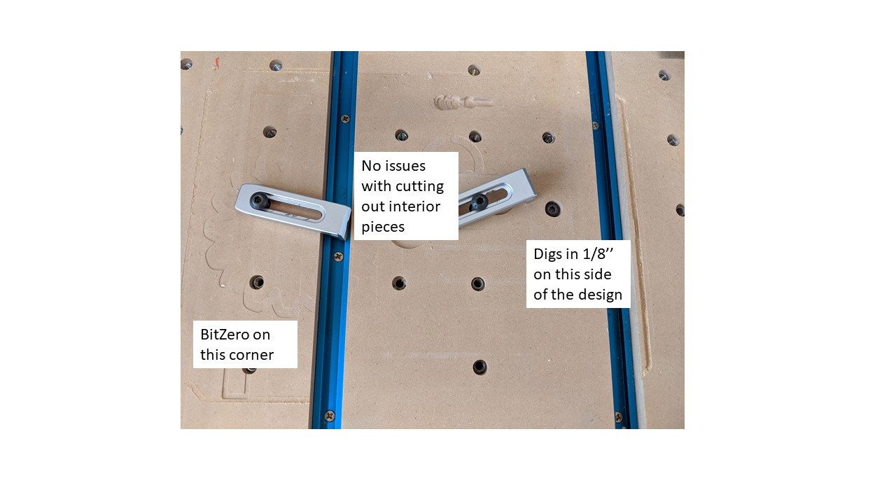
Then I cut my design, shown here. There are only 2 toolpaths, both of them set to the same Z depth. The interior “windows” cut out just fine. I measured the thickness of the material to be 0.2350 so I set my Z depth to cut to 0.230, and it was almost spot-on and didn’t cut into the spoilboard. But on the outside run, it decided to dig down into the right hand side by almost 1/8"!
After this, I removed the material, and checked the Z axis. I tried to move it up and down but it’s solid, and not slipping on the pulley. The collet was still very tight - no movement there.
I fought this for years…and found a way around it by
(1) lowering the Z off the stock
(2) predrilling a hole for the stock,
(3) ramping the Z down VERY slowly or
(4) lowering the Z down feed to VERY VERY VERY slow.
I cut Aluminum 95% of the time and have had almost 0 errors following those rules (In that order). 4.7 year owner…PS If you can afford it…sign up for the new Z-Plus… it will solve all the Z issues.
Travis - yes, I think so. When I roll the v wheels on both sides of the x plate, the whole carriage moves.
Just wondering, doesn’t z axis slipping result in not cutting deep enough? In this case, the depth on the left side of the piece is fine, but the depth on the right is way too much. So it’s like the machine is moving down the z axis but not counting it
Hi Richard,
Can you help me on #1 and #2? What do you mean by lowering the z off the stock? And by pre drilling, does that just work for holes? Thanks.
My thinking was that’s it’s weird it’s deep on one side but not the other - so maybe the Bit is being pulled down on one side due to loose v wheels on the side plates. So it’s not the z plate being loose - it’s the whole z carriage being dragged down?
My thinking was that for this profile cut, the bit goes in one direction (say, up) while cutting the right side, while going in another direction (down) when cutting the left side. So there might be asymetrical slop in the Y axis.
@RichCournoyer: you’re on ! But what’s your bet? Weak Z?
Ok, so checked my v wheels. There was some asymmetry, but none were loose. The v wheel on the RHS, front, of the y axis was tighter than all the others. So loosened them all up, and tightened them again until just making contact. I confirmed there is no slop.
Since the OEM Z is limited to about 18 lbs of downforce, it is well known among the Aluminum cutting group that loosing Z steps is VERY easy when entering into a part using the END of an end mill (Why the heck do they call them End Mills if they hate cutting on the End (rhetorical question).
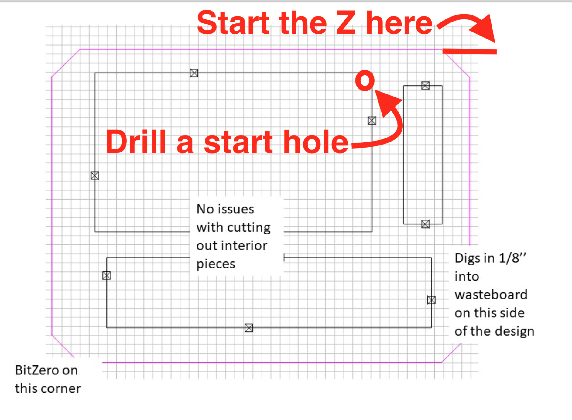
Anyway it would be great if we could place a mark, or tag that denotes WHERE the cutter will start the cut. This was we could have it start from a hole that we (e.g.manually) place on the part (For say a pocket) OR we could place a polyline leading into the edge of a part, and have it start at the end of this polyline (which as been drawn off the part’s edge.