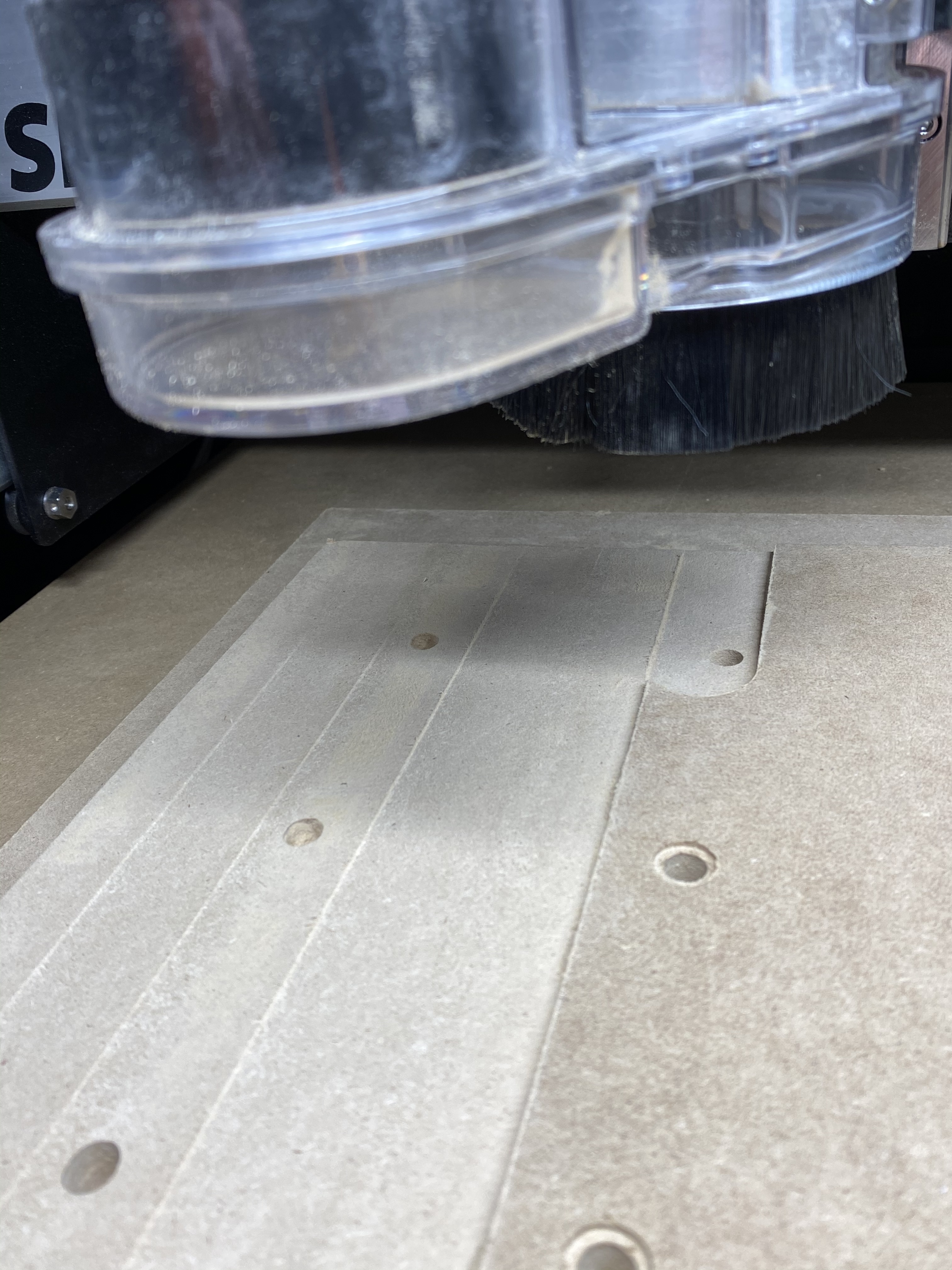
I used fusion 360 to create a waste board. The pocket holes and countersink tool paths went fine, but when I surfaced it with my 3 tip surfacing bit, I ran into problems. The bit made 6 passes and all were at different depths. I had set my off set from top of stock at 0.5mm and the deepest pass it cut measures 2.2mm. That’s way off and I’m confused. If they were all 2.2mm I’d feel like it was a simple fix but the fact they are all different depths within a 0.1mm is confusing. I’ll explain what I’ve checked and did prior to running g code. Belts are tight. Wheels are tight. Machine is square and level, used bit zero to get x and y with a probe and then installed the surfacing bit and used the bit zero to get zero. I then ran the cut and ended up stopping after 6 passes because it just was all wrong! Any help would be appreciated
Terry, I use the imperial measurement and I take off 0.010" for each pass and that is also my tool depth of cut. So I made a rectangle of the spoil board with some extra so I go over the edge and I pocket 0.010". If that does not make a perfectly level surface I rezero and run it again taking off 0.010" each pass and only one pass. I use pencil lines all over my wasteboard so I can tell when the surface is one depth because all my pencil lines are gone. After the first pass I move to where the lines are still visible and zero there. Obviously this is a low spot and wont waste time making multiple passes. I can usually get mine level in 2-3 passes.
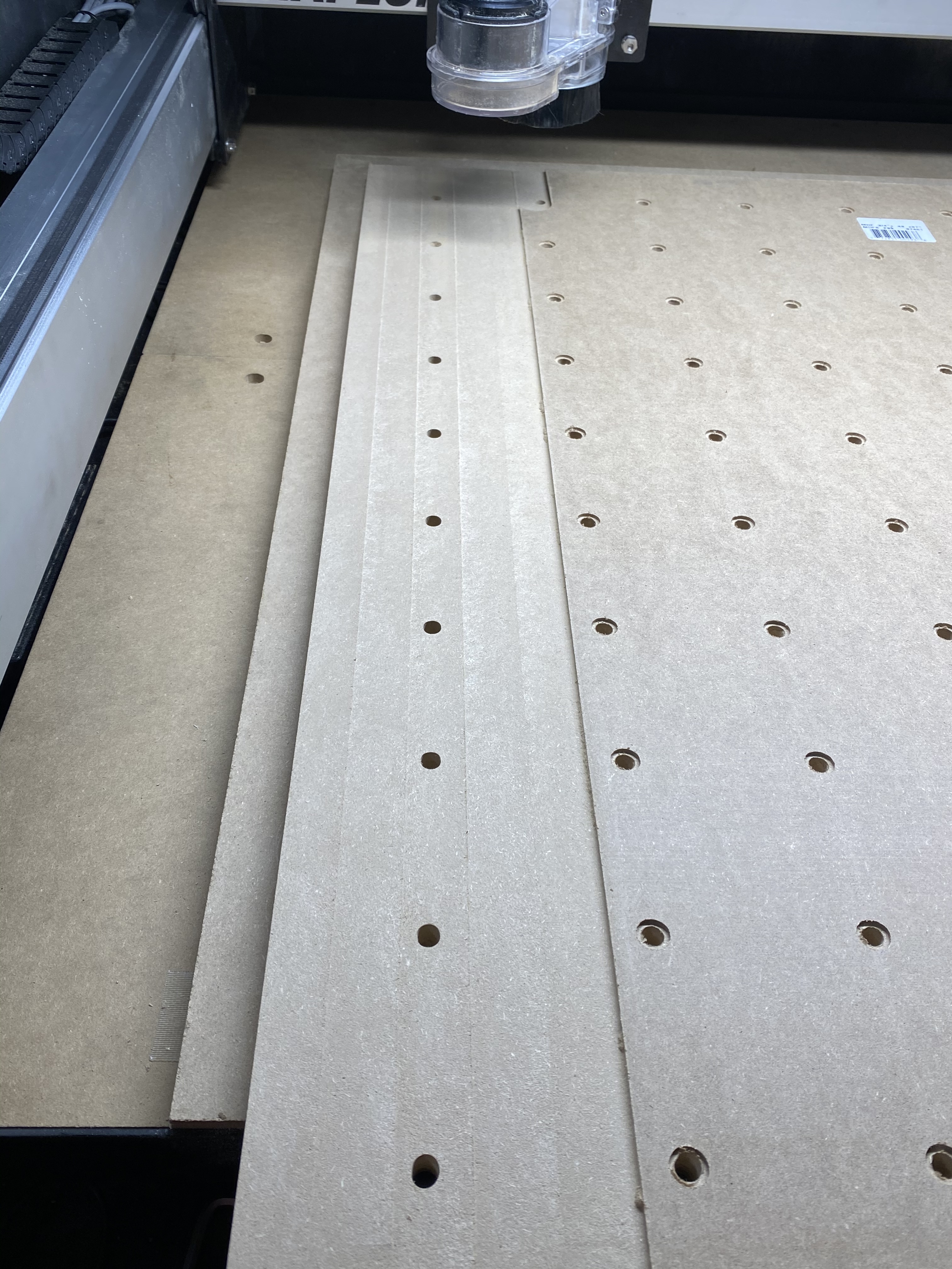
Attached is a document I created for making a torsion box. In it is instructions for leveling a wasteboard. Also attached is another document discussing making a wasteboard for a Shapeoko 3. I can see in your picture above that your wasteboard is bigger than your cutting area and that is ok but if you want to put a larger piece of material on you would have a gap under the material. This can lead to problems.
I use examples from an XXL but the instructions are useful for any size Shapeoko. Let me know what you think.
torsion_box.pdf (2.0 MB)
spoilboard_considerations.pdf (1.3 MB)
Additionally here is a copy of my custom tool database for the fly cutters. One is a Whiteside 6210 and the other is a 1" Chinese cutter. Both are equilivient.
| number | vendor | model | URL | name | type | diameter | cornerradius | flutelength | shaftdiameter | angle | numflutes | stickout | coating | metric | notes | machine | material | plungerate | feedrate | rpm | depth | cutpower | finishallowance | 3dstepover | 3dfeedrate | 3drpm |
|---|---|---|---|---|---|---|---|---|---|---|---|---|---|---|---|---|---|---|---|---|---|---|---|---|---|---|
| 601 | whiteside | 6210 | Fly Cutter | end | 1 | 0.125 | 0.125 | 0 | 2 | 3 | 0.125 | 0 | Shapeoko | MDF | 10 | 80 | 16000 | 0.01 | 1 | 20 | 80 | 16000 | ||||
| 602 | Sugelary | X002JUT7TF | Fly Cutter | end | 1 | 0.125 | 0.25 | 0.25 | 2 | 3 | 0.25 | 0 | Shapeoko | MDF | 10 | 100 | 16000 | 0.01 | 1 | 20 | 80 | 16000 |
One tidbit is the Carbide3d Tool Database Definitions for CC.
carbide3d_tool_database_defenitions.pdf (30.5 KB)
All of the information I listed above I used Carbide Create. Fusion 360 is a great program but some programs are just easier to use than others. Fusion 360 is easy to get lost in the weeds. Simple projects like surfacing a wasteboard are done easier and possibly faster in Carbide Create. Plus in writing the documents everyone can use Carbide Create and not everyone has Fusion 360. I used imperial measurements and some like metric. Since most of the Carbide3d tools are in inch and the Whiteside 6210 is 1 inch I just used imperial. You can convert to metric but I just want my wasteboard surfaced quickly and easily and am not a purist about measurement systems.
I’m the opposite of you in this regard - after 50 years of measuring things in metric, I have an instinctive feel for what Terry said, but have no instinctive feel about what 0.010" is. So converting to metric is often more than just “because” - it aids understanding.
Hey Terry,
Do the ridges get deeper, or are some shallow then others deep and then shallow again?
If it’s always getting deeper, perhaps the bit is slipping, or your router is not trammed properly?
Hi Terry,
As there is no mention of it in your initial post, have you checked your tramming? If this is out then you would expect to see cuts like this especially with the wider diameter cutters people use for flattening washboards. If the cutter is not parallel to the machine base or washboard, then either the leading or trailing edge of the cut will be deeper. Definitely worth the time to check tramming and nothing a few bits of tin foil as shims won’t sort out.
Lot of good into on the forum with regards to tramming if you need more info.

I had a similar issue when I just rebuilt by XXL… Tram lines running front to back. So certainly look at the post above for squaring the spindle. I used a slight different process using one of these… Digital Angle Gauge.
I put it on the gantry and zeroed it. Then put it on the spindle mount and found I had a .7 degree deviation. It then depends on the style of z-axis you have. I have the original one, so for me it was a matter of loosening the 2 spindle mounting screws and adjusting until I read to as close to 0 degree’s as possible.
Produced a perfectly smooth waste board with no tram lines in any direction…
Just to add one more bit to this…
If you have tram lines running front to back, your spindle is tilted left or right of center.
If you have tram lines running left to right, your spindle is tilted front or rear of center.
The trick is to then figure out why 
If you are seeing visible lines after surfacing your wasteboard then you router needs to be leveled. Your fingers are incredibly sensitive instruments. So look across your wasteboard and see which the lines are running to determine which way your router needs to be adjusted. If the lines run from back to front your router needs to be adjusted side to side. Feel the lines and if the high side is on the left your router needs to move to the right. If the high side is on the right the router needs to move to the left. The pattern is whichever way the high side is you move the opposite way to level the router. If the lines are running are running across the waste board your router needs to be tilted in the front or back direction. Again determine which you the high side is and your router needs to move the opposite direction. So if your ridges are higher in the front the top rear of the router mount needs to be shimmed with folder up aluminum foil or brass shims. If the ridges are higher in the back then you need to shim the bottom of your router mount to level out the ridges.
Now getting the router level on both directions can be tricky. One aide is to remove your router from the Z carriage. Use the 1 2 3 Set Up Blocks machinists use for set up. You can buy them on Amazon and other places relatively inexpensive. You can use two of the blocks to level your router mount in relationship to the wasteboard of both directions at once. You still may need to shim the router mount front to back with shims and the left to right can be done by loosening your mounting bolts and/or the HD eccentrics present on some newer mounts.
After you get your router square to the wasteboard you will need to resurface again to remove the ridges. If you can faintly see and feel ridges you can just run a sander across the wasteboard to remove them. But if you are seeing and feeling major cliffs you need to tram your router mount.
Hey Guy
Thank you for your reply. I wanted to run my exact issue by you. I made the entire waste board in fusion. I used 3/4 mdf and made my holes 8mm and my countersink 12mm. I then set up the surfacing to go 0.5mm so barely skim the top. When I ran the first 2 tool paths (holes and counter sink) I do so by placing the 3/4" on the factory waste board and all the tool paths ran flawlessly. I couldn’t just flip the board over and do the surfacing because I made my waste board 32"x32" the router cannot make it to the last 2’ of the board when i push it as far front as possible (wastteboard hits the front guard) To fix this i placed another 3/4" wasteboard under the one I want to surface then moved it 2’ forward (over the front guard) and re zeroed my xyz with my bit zero. I made sure my offset was 0.5mm and from top of stock not bottom to avoid issues. In theory I did everything right. I realize now that the scallop effect is from a trimming issue but what is getting me confused is to why the depths of the passes is 2mm. That’s way past what was programmed. The same metric measurements were used on the holes and countersinking and they went perfect. Why would the surfacing be so off? Only thing I could think of was the second waste board to get the heights I needed in order to surface the entire board. Since I used the bit zero to set x y with a probe and then z with the actual 1’ surface bit, all should have gone as planned. Any ideas would be helpful my friend.
Does the bit zero work with a surfacing bit that typically has a concaved center. that would be about 2mm off. bit zero or bitsetter?
No. Disable the BitSetter when using endmills which do not have structure along the center at the depth of cut.
Hey Gerry
It started to get deeper then 2 passes were identical then less deep. In total I made 5 full passes and when the 6tth started it looked deeper. The 4,5 passes were identical so I thought maybe it was working but the 6 was deep. They are all different depths except 4,5. The g code was set up for 0.5mm so I dont understand why all of them are way off. I you look down to one of guys posts I replied with my entire set up and situation so maybe that will help shed some light. Im very discouraged right now.
I disabled my bit setter because it was not able to hit the center of my 1’ surfacing bit. Its a bit where the middle is open and has 3 tips so it would never hit the bitsetter properly and since there is no tool change needed the bit setter is kind of useless if you use the bit zero to get zero. I used a probe to get x and y with my bit zero, then installed the surfacing bit and then set zero with the bit zero so, why it went 2mm deep instead of 0.5mm deep is driving me crazy. makes no sense.
i used the bit zero. bitsetter would not hit the blades as they are concave in the center. Bit zero hit perfectly on the bit ends and should have been good for 0 but still went 2mm deep and other degrees of depth but none were .0,5mm
i like the last part of your comment. perfectly smooth and no tram lines lol. I wish. So I have the z plus and I will try the tram techniques for the scalloping but the depth is where im left scratching my head. Should of been 0.5mm and i have 5 passes and were not at 0.5mm. some were 2mm deep. Makes no sense. Bit was tight, bit zero was used to set z axis at 0. confused over here.
Very odd indeed. If your machine is okay, then either you have a wavy bit of mdf or your code file is actually a model of an abstract sculpture or a tilled field:)
Can you post the .nc file so we can discount it?
gladly but please be kind as this was my first ever project on fusion and I am big time newbie. Here is the .nc file. SURFACE MASTER!.nc (1.0 KB)
this was my hole and countersink tool paths
HOLE AND SINK.nc (92.8 KB)
Folks may have already mentioned this but if you are getting varying depths put a black mark on your router bit where it meets the router collet. After a varying depth pause the CM application and power off your router if you do not have BItRunner. Look at your black mark and see if the bit has lowered and there is space between the black mark and the collet. Or if the black mark has disappeared loosen your collet and take the bit out find your black mark and reinsert the bit and tighten it up. This is to see if your bit has come loose and is coming further out of the router or being pushed up higher by cutting forces. The black mark should be right where you made it if the bit is not moving in the collet.