I’m trying to figure out use the 1/4" McFly to level my project after filling several pockets with epoxy.
I thought it would be either a texture pass of a rectangle that’s the same dimensions of the stock or possibly a shallow pocket (although the usual cut pattern of spiral-out isn’t desirable), but I’m not seeing the McFly tool listed in the library for any of the tool-path options.
I’m sure this is covered somewhere, but I’m apparently search-challenged today and can’t find instructions or examples on how to do this.
The McFly tools are only listed under Mills for Hardwood & Softwood.
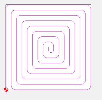
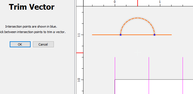
I really don’t like the plunge in center / conventional cut pocket pattern, so I will create a single spiral vector and use a contour path with no offset.
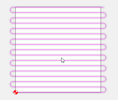
Or a zig-zag, lace-cut pattern and cut with the grain
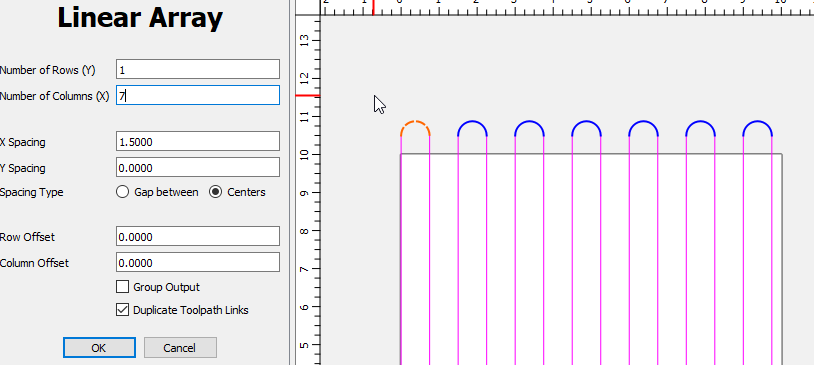
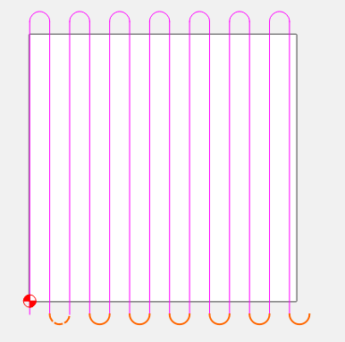
Ah, okay it’s a contour cut, so I would need to create the zig-zag pattern, based on the width of the McFly, so there is sufficient overlap with each pass and also runoff at each end to get clean edges.
I’m probably approaching my limit on stupid questions here, but… onward. What do you use to create the pattern? CC is okay (and I’m still learning the ‘just above basic’ stuff, but I haven’t found it to be overly intuitive or cooperative when it comes to creating repetitive and uniform patterns.
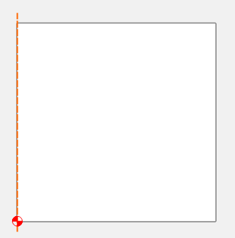
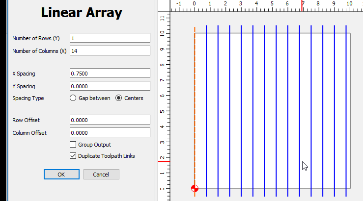
I’m trying to think how I’d create the zig-zag in CC you did and maybe start with the Polyline tool, figure out how to get each end aligned straight, rounded and evenly spaced. OR and more likely, I’d just find a similar zig-zag pattern online, trace it and resize it until it covered my stock size and forget about trying to manage the amount of tool overlap as long as there was some.
I use a Whiteside 6210 fly bit which is similar. If my project is 10" x 10" I make the rectangle/square 10.5 X 10.5 so I get a full cut of the project and not leave a small lip around the outside. My step over is 30%. You could get away with up to 50% but depending on your router tram you tend to get ridges if your router is not perfectly level front to back and/or side to side. When you pick the tool that is in the C3D tool database you can edit step over or create a custom tool based on the original McFly tool.
When surfacing epoxy or my spoil board I set the depth of the pocket at 0.010". I also set the depth of cut to 0.010". So I get a single pass. If I still need to make another pass I jog the router off the project and jog down to -0.010 and reset Z zero. The first pass you cut off 0.010". I just start the file over and repeat as necessary. I set the initial Z zero on the part of the project that does not have epoxy on it. On the spoilboard I scribble pencil marks all over the spoilboard and make a single pass. If the pencil marks still show in areas I jog to those areas and reset Z zero and start the program again. It usually only takes 2 or 3 passes to get my spoilboard leveled out. If you have deep cuts in the spoil board you do not need to completely remove them. The material will sit flat on the parts that are level.
Thank you! That was a perfect explanation for how I think about managing the machine and the cuts in my projects. The depth, stepover and passes questions were brewing and that answered them.
Defining the zig-zag pattern is probably the simplest of the issues, but concerning me the most so far.
Humility comes in realizing that while I may know something you don’t, you know a lot of things that I don’t. And neither one of us know more than 1% of all the knowledge there is to be had. (likely much less)
You know that might be an easy toolpath to add to the array of possible toolpaths. I think Fusion360 has a facing toolpath in it repertoire. A simple facing zig zag with smooth transitions might be a good suggestion for the next revision of Carbide Create