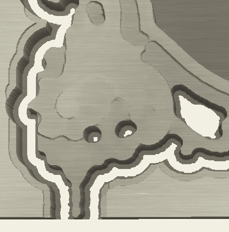
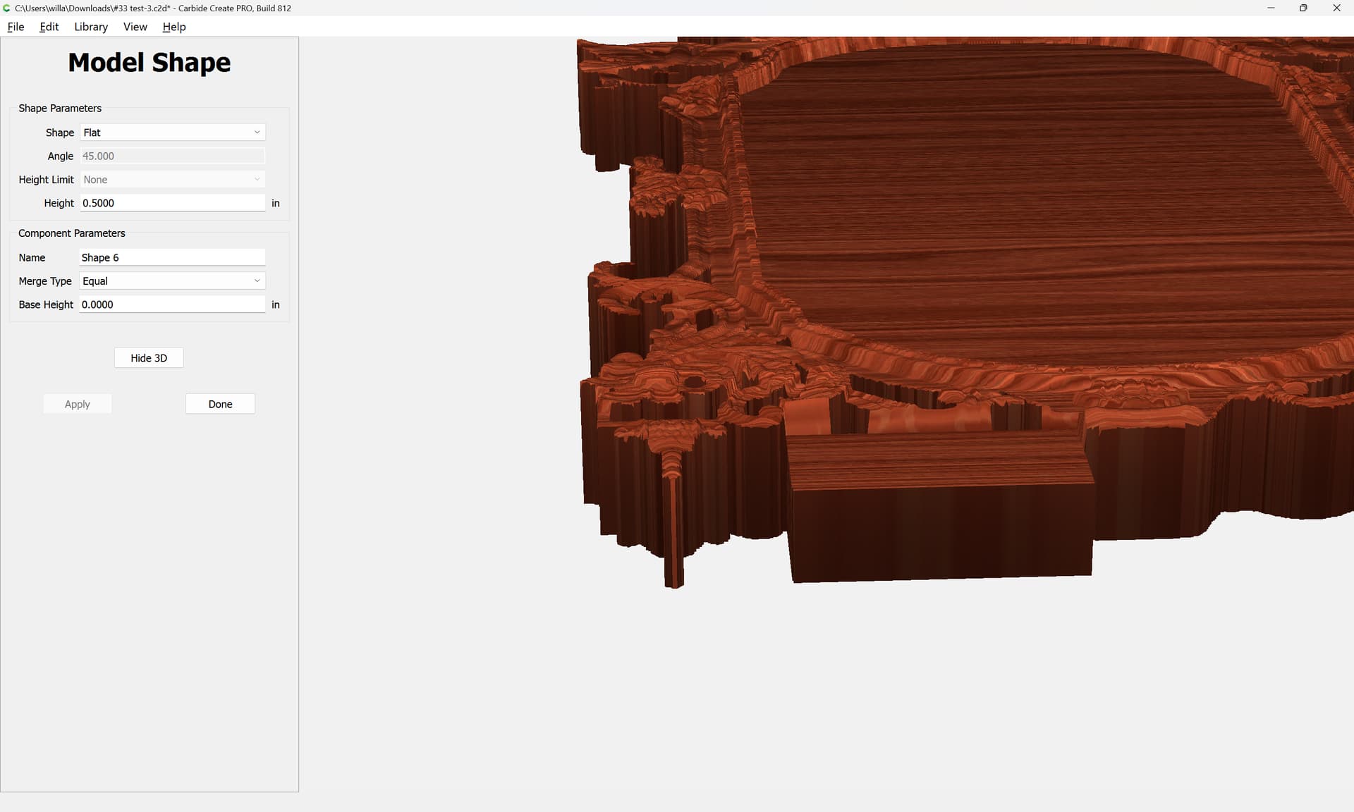
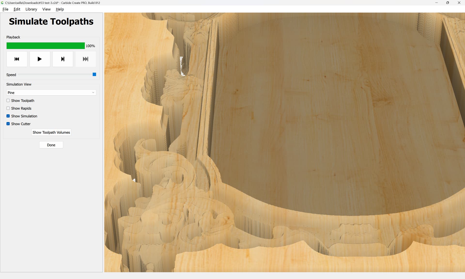
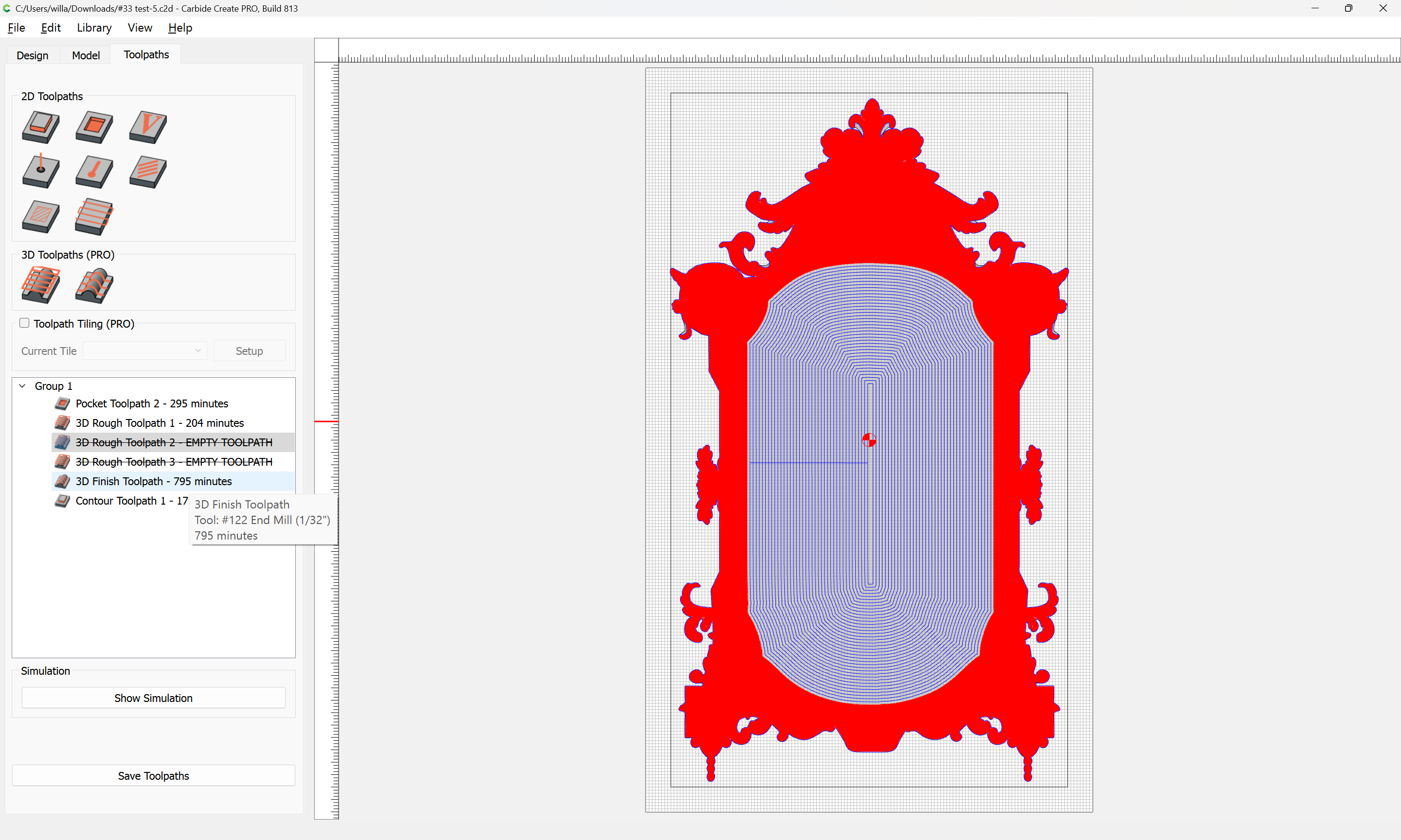
I have been asked by my daughter to make her a picture frame. I added outline vectors to pocket the middle and to speed up the 3d cuts. I have the stl she chose and created tool paths. In the simulation, as in the actual cut project, there are uncut ledges around the base I can’t figure out how to get them off.
If there are better ways to set the toolpaths, please let me know that too.
If you are willing to carve into the wasteboard, the other thing you could do is to say that the Stock Thickness is deeper than the actual stock. If you say it is 1/16" deeper than it really is, the ball mill will plunge that much into the wasteboard, and that would be deep enough to get past the ball portion of the ballmill.
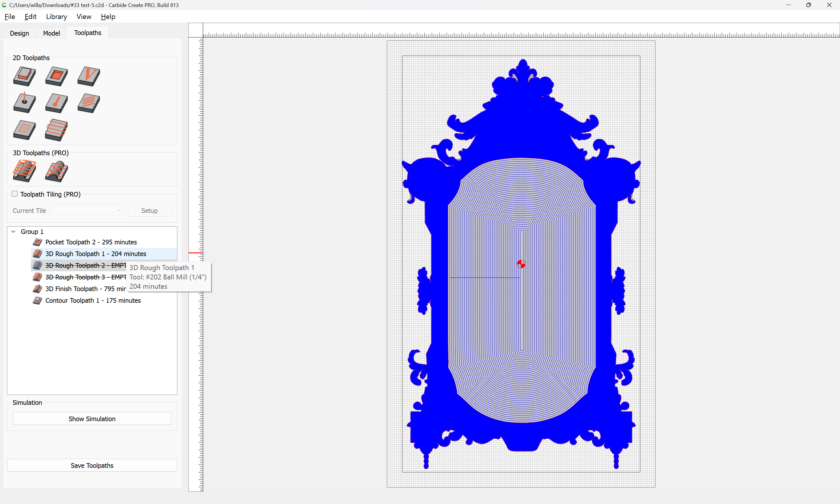
I worked on the file some more and changed my first roughing bit to a 202 as suggested.
I added additional iterations of 1/8 and 1/16 but don’t see any changes, just additional time cutting which leaves to believe I did not understand the suggestion correctly.
I will be purchasing longer bits that will cut all the way through the material but used the feeds and speeds for what was in the respective databases for the bit diameter.
I would greatly appreciate someone looking at my file and telling me how to make it better or quicker.
Due to the time estimate in toolpaths, I would prefer not to cut it as the cut time will exceed the amount of time even I can sit and watch the machine work.
I have an additional question on setting Outline vectors on a STL. I just kept entering numbers until what I was hoping for showed up. I hope there is a better way.
The community has written a bit on this sort of thing at:
I will note that all the mirrors like this which I have seen have not been made of a single piece, but are instead pieced together in sections — I’d worry about warping.