Still new to doing CAM in Fusion.
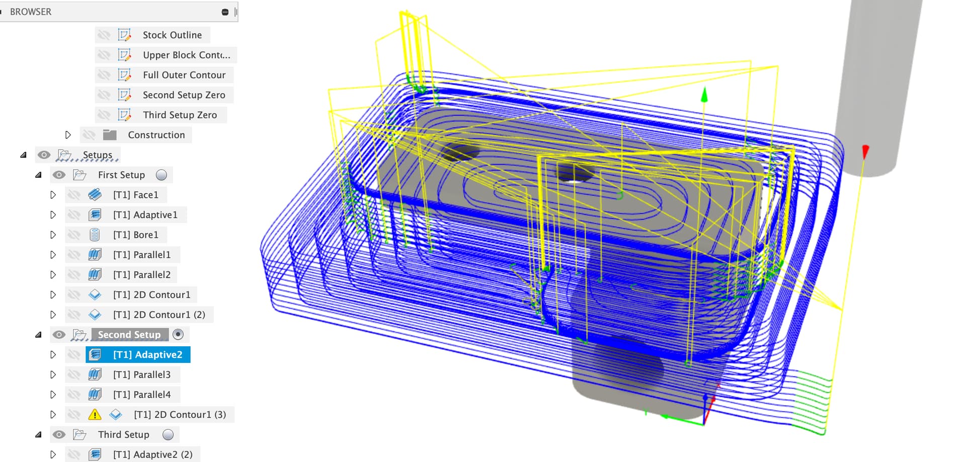
Here is the adpative toolpath, I was concerned that it seems a lot of tool edge engagment. Total depth of part is only 6mm

Still new to doing CAM in Fusion.
Here is the adpative toolpath, I was concerned that it seems a lot of tool edge engagment. Total depth of part is only 6mm
What material?
It’s your stock accurately defined?
I don’t like the initial plunge.
Sorry, Aluminum.
That is what I was worried about. A friend help me find where to get it do do this in small passes.
The plunge or the job?
Which machine do you have? Which Z?
I think you could easily do a full depth adaptive clearing, but I’d decrease your optimal load a bit. You probably also want to leave some stock (radial and axial) and cone by with a couple of finish passes for the surfaces and the profiles.
Ok Would anyone be kind enough to look at this model in Fusion and suggest toolpaths with Nomad Tool #2 in Aluminum?
Which machine are you using?
Shapeoko 3/4 / Pro?
Nomad?
And…
What size stock are you planning to cut this out of?
Any plans on how to hold it whilst you cut it? (Vice, glue & tape etc.)
Which tool are you referring to with #2 BTW? There are 3mm holes in the part which means something smaller than the 1/8" will be needed for those.
I did state this was on the Nomad and with Aluminum . The small holes will be drilled later.
I have 2" wide 1/2 thick 6061 stock
I tried using 3d adaptive to start and while it produces a good toolpath, it left me with two issues, firstly I could find no way to do a finish pass that created a valid toolpath, and if I tried to run the adaptive it was trying to do full plunge into stock. I don’t think the machine can handle that. Even with the few test pockets I did with carbide create it seem to struggle which was discouraging as milling small aluminum parts was my entire reason for the machine.
Hang in there, the machine can definitely do it but you need to manage your expectations and therefore your toolpath
Have you seen that video from Winston about machining aluminium on the Nomad ?

Share you latest file with that try and we’ll have a look?
Entry into aluminium should be with ramping, preferably helical ramping. If you do enable helical ramping it should be fine
OK,
I use a Shapeoko rather than the Nomad so my knowledge of what the Nomad can do is limited.
In general for hobby machines depth of cut is the enemy, low depth cuts at high RPM moving fast through the material are mostly better. Chip evacuation can also be an issue, especially in deep holes where some sort of air blast or lubricant helps a lot.
In the adaptive strategy there’s a box “Maximum Roughing Stepdown”, start with that at, say 0.5mm (guessing for Nomad, I use 1.5mm on a Shapeoko) and accept lots of passes at the stock to rough it down.
Also leave some stock to leave and come back with finishing passes, 2D contour works well for this.
Are you comfortable with re-mounting the part and getting a consistent workpiece zero for all three angles you’ll need to machine it from?
I think the toolpath shown is plunging outside what it believes to be the stock but that needs to be definite, I agree a helical ramp is safer.
@Julien I’ve seen those videos, and as helpful as they are (I have written notes for all the reciepes), applying them to actual toolpaths was not as straight forward as I would lilke.
I had at least at first helical ramping on. Honestly I’ve only tried once to actually run it once on the machine. I’m startign to suspect one error on my part is not having the stock in Fusion the ACTUAL stock size other than the Z height.
@LiamN Leaving stock was one of the issues even in Fusion toolpath generation. There didnt’t seem to be ANY contour path that worked even remotely and machining the areas I need without destroying other areas. And on another version of this I was only flipping it and doing a surfacing to remove the excess from the bottom.
yes emounting and zero I can handle.
For sure you need to have the stock declared in Fusion match the real one, since Fusion will aggressively approach the stock / plunge nearby as Liam mentioned.
Share the Fusion file with the toolpath you are struggling with?
This has What I think would be a working 3d Adaptive
CineTape Horn Mount HELP v2.zip (175.9 KB)
I also Changed the stock size , I realize now the way I did it before was dumb. While this is still not the actual stock x,y it accounts for enough that I’m maching away enough to clear for contour passes
That file is quite a bit further forward.
Fusion needs quite a bit of help with doing things like contours, I normally project the contours I’m going to follow on a part like this into a sketch to then tell Fusion what to do.
I’ll supply an example later if that’s helpful.
ok, at first look, a few comments:
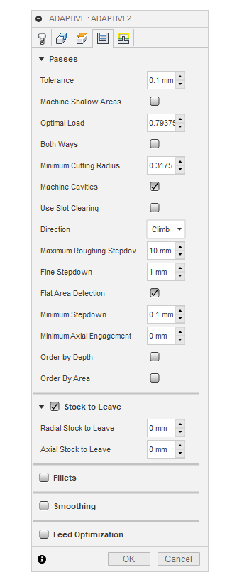
For the adaptive toolpath, you have your optimal load set at 1.27mm, which is way too high when using a 1/8" endmill in aluminium on a Nomad. In that video Winston recommended 0.305mm (0.012") optimal load.
On the other end you have max roughing stepdown at 0.25mm, Winston recommended 0.762mm (= three times less passes), but maybe pick 0.5mm to be on the safe side for a first try
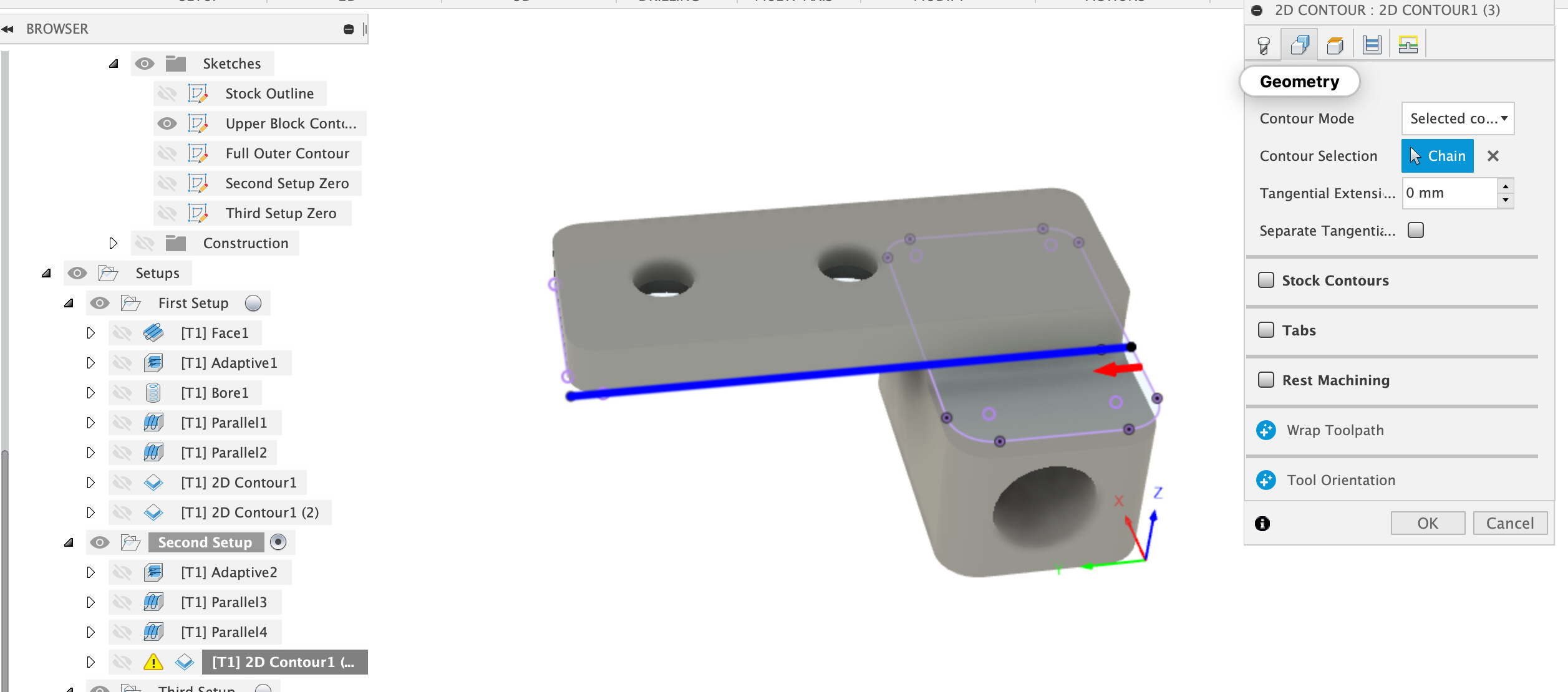
for the third toolpath, what do you want it to do ?
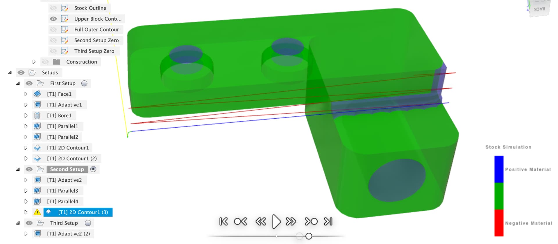
It does not have rest machining enabled, so it’s not going to be aware of the previous operations (and since you have stock to leave set in the adaptive toolpath, it matters)
beware that the height of your piece is 11mm, so you’ll need to make sure your 1/8" has a length of cut of at least that, or it will rub
the inner lower holes have a diameter smaller than 1/8", so you’ll need another endmill and toolpath for those
@Julien Thanks… Lets ignore the contour for now. That was just my most recent attempt to find something that would create a toolpath that make any sense. The adaptive has left .5mm radial and axial and I cannot find anyway to create a valid removal toolpath. I played with horizontal and that looks promising for axial and I might figure that one out. But the radial ???
One of the many ways to skin this cat would be to duplicate your adaptive toolpath, check rest machining / from previous operations, uncheck stock to leave, and that second 3D adaptive toolpath will happen to shave off the 0.5mm axial and radial left by the first 3D adaptive toolpath
I’m not saying this is a great finishing strategy…
Just FYI, I’m also having a go at some toolpaths for your model, it’s taking a while though as I’m doing that whilst watching my machine run.
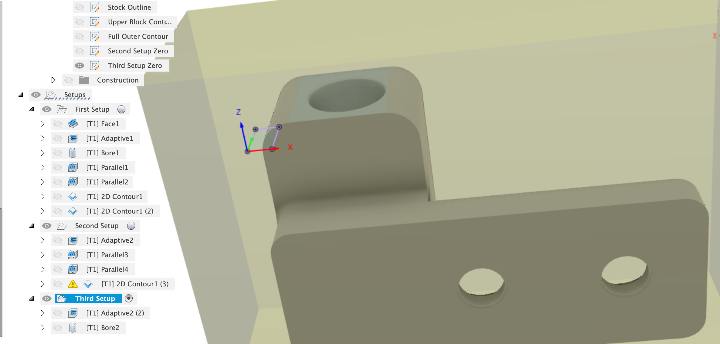
Here’s a version with some more ops to it to get further round the part, building on what Julien already did.
Do not assume that any of the feeds / speeds / depths are any good for a Nomad, I know very little about the Nomad. Also I am not sure that the bore operations are safe without air blast or coolant on the two flute 1/8" especially the deep bore in the third setup.
CineTape Horn Mount HELP v2 v13.f3d.zip (290.6 KB)
I’ll go through the changes in order to explain why it’s like it is. There’s many ways to do any part and this is just one. It’s not complete, there’s a couple of bits that aren’t machined and I’d consider removing some of them from the design unless critical. One needs a ball end mill to finish.
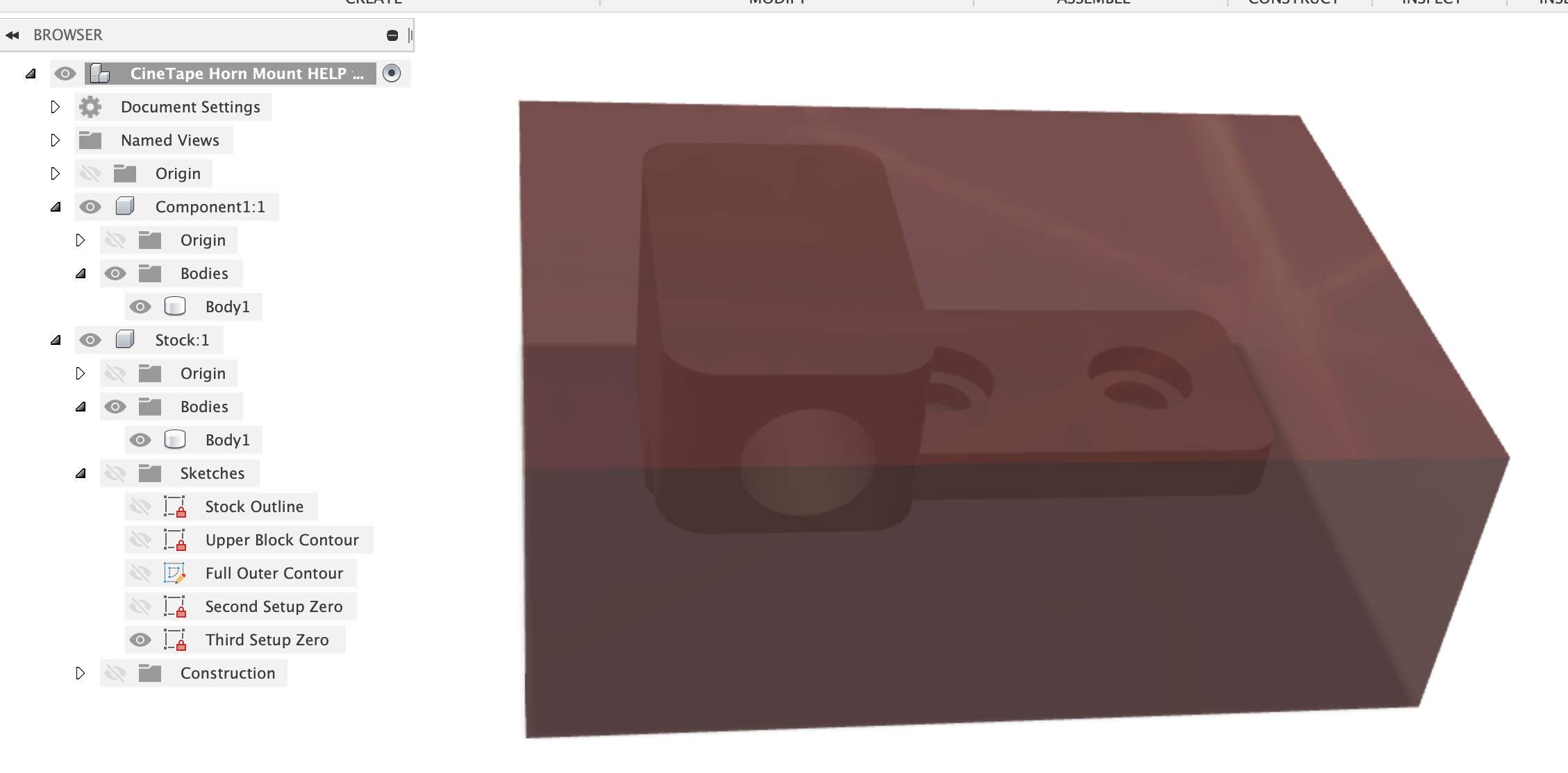
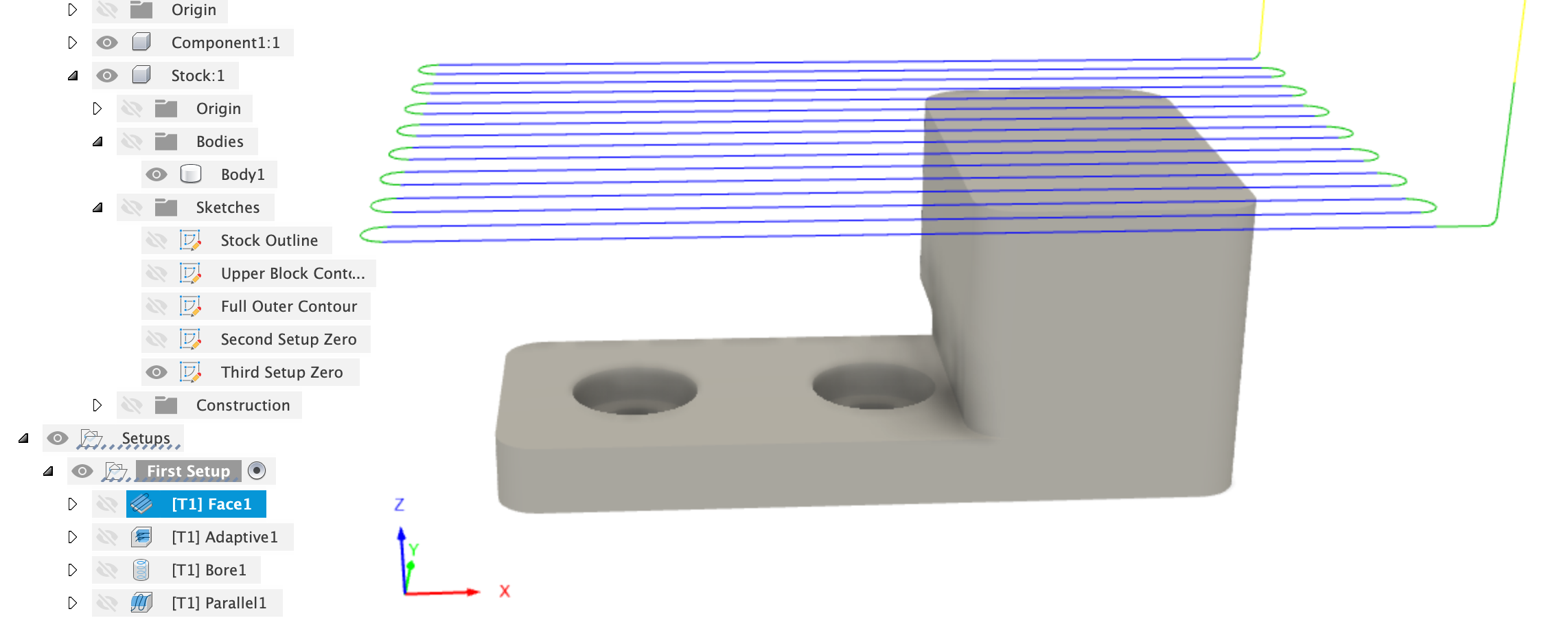
First I modelled the stock as an object, this also lets me put some sketches in the stock to use in setup.
First Setup
The first setup is for the major work, I set the Z plane and X axis specifically and selected a zero point, note that I set the base of the stock as zero so that we don’t have a dimension problem if the stock isn’t perfectly 1/2". You’ll need to zero off the baseboard, vice or whatever you are mounting the workpiece on.
First operation is a facing to take about 0.2mm off the top and face the part.
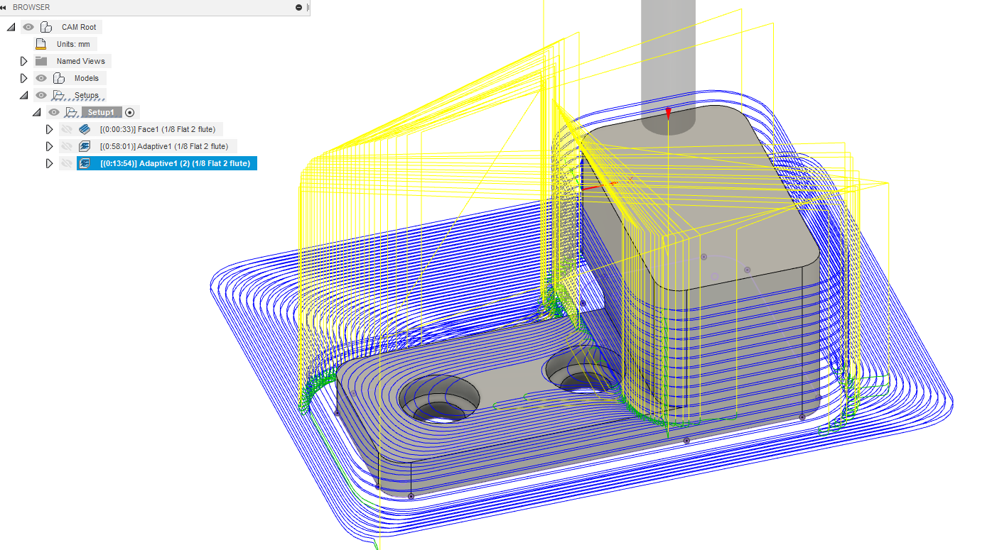
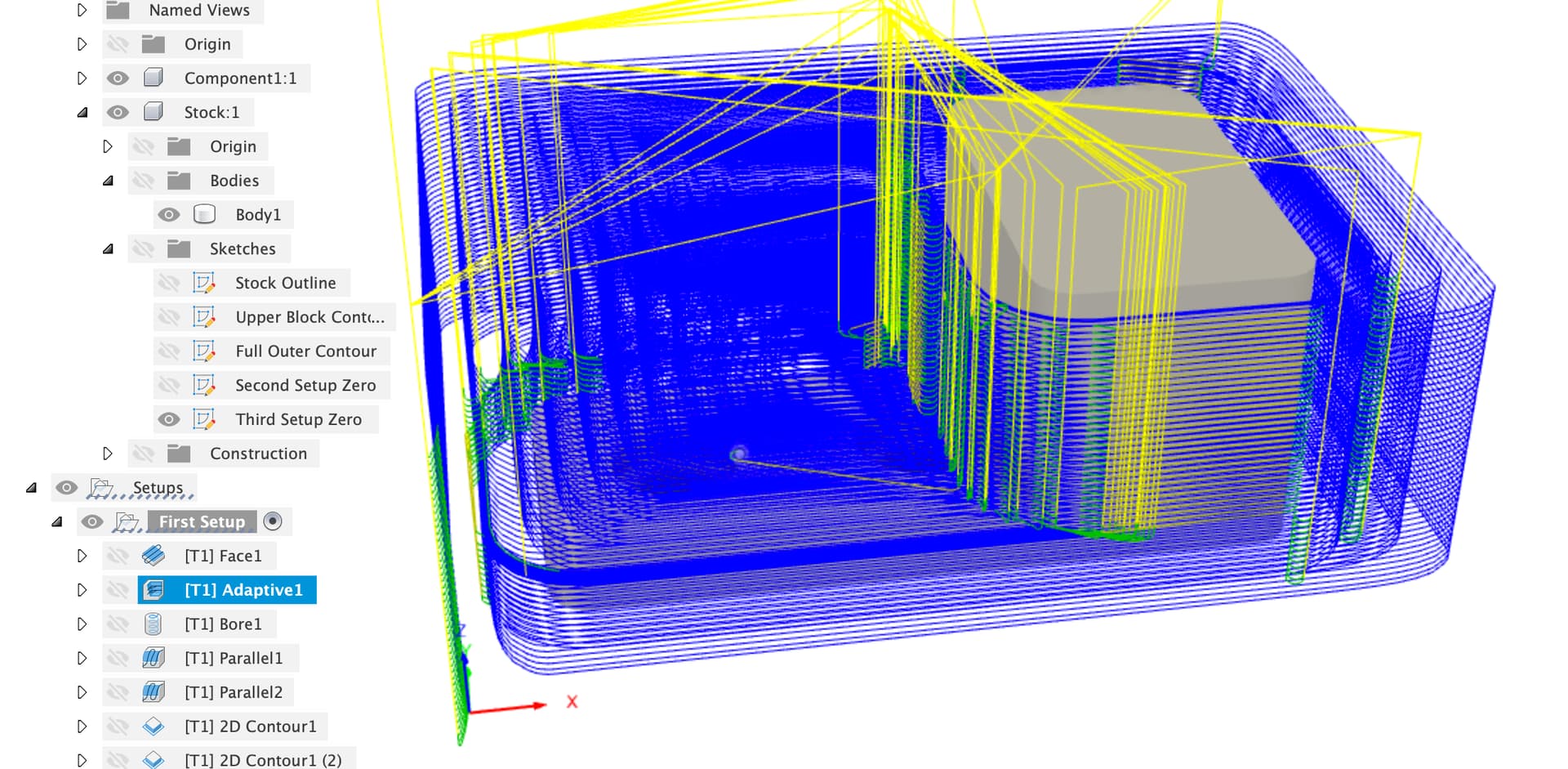
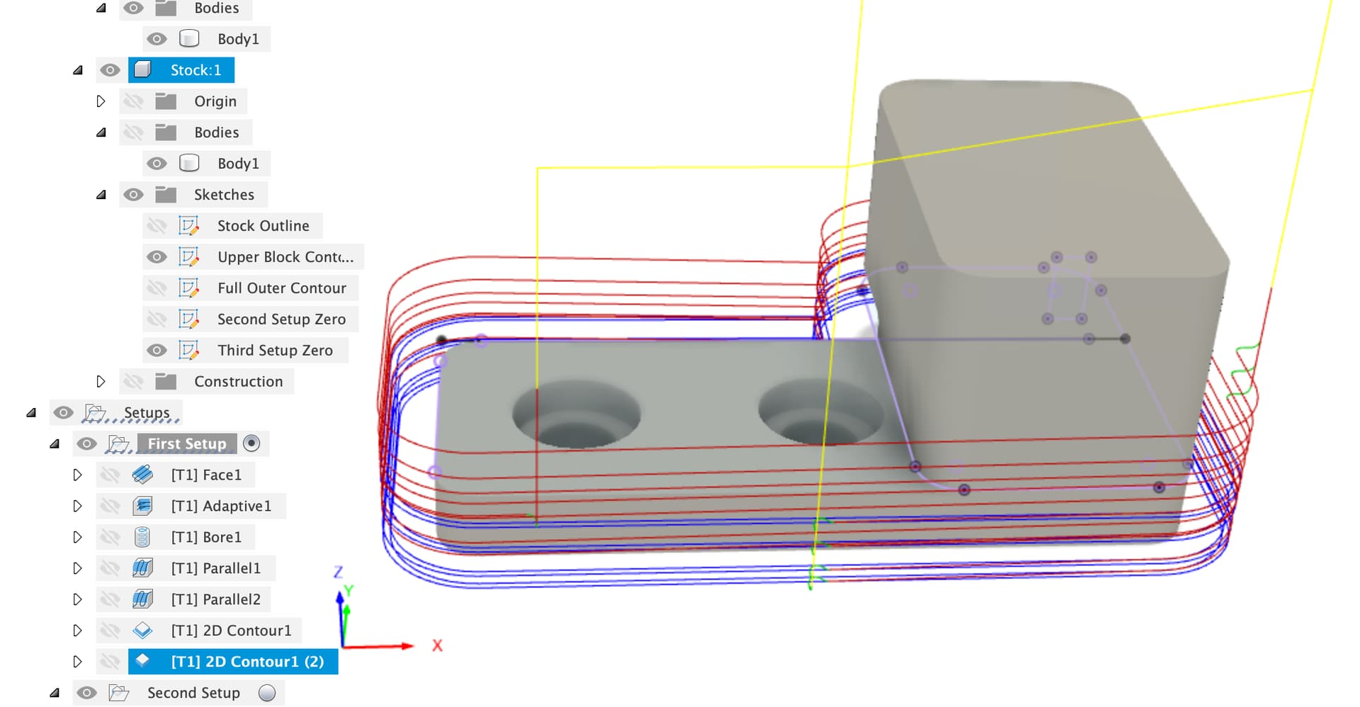
Next up is an adaptive clear
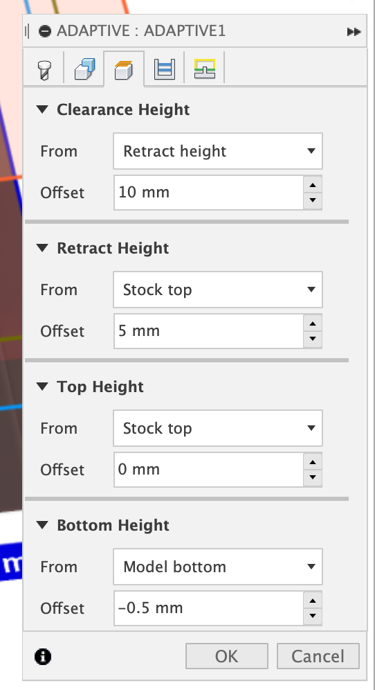
This goes all the way to the bottom of the part, carefully setting the bottom height to -0.5mm from the part to make up for the axial stock to leave does this.
Also note that the adaptive is entering from outside the stock so we don’t need to worry about helical ramping. Also the Adaptive is always cutting on the outside of the workpiece to give us a much better chip clearance through this stage.
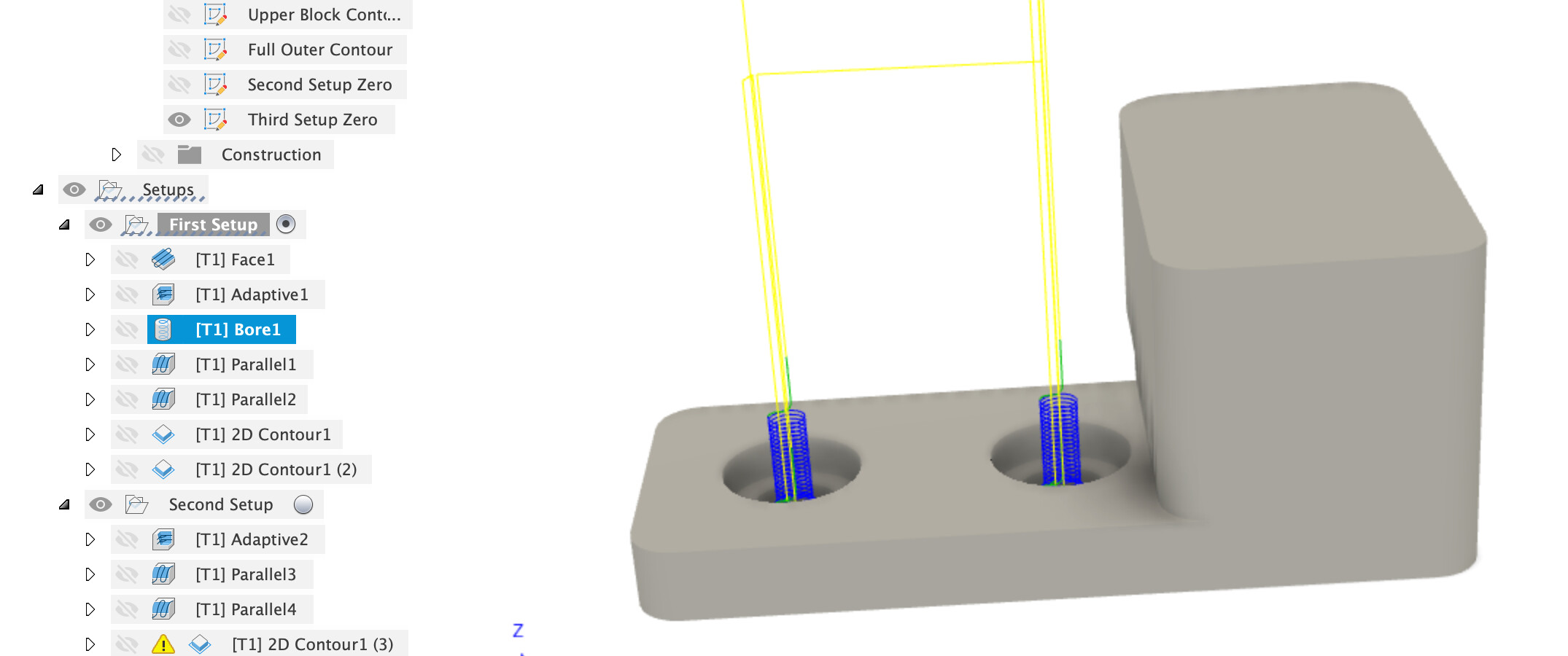
A boring op gives the upper part of the small holes (which you’ll finish by hand)
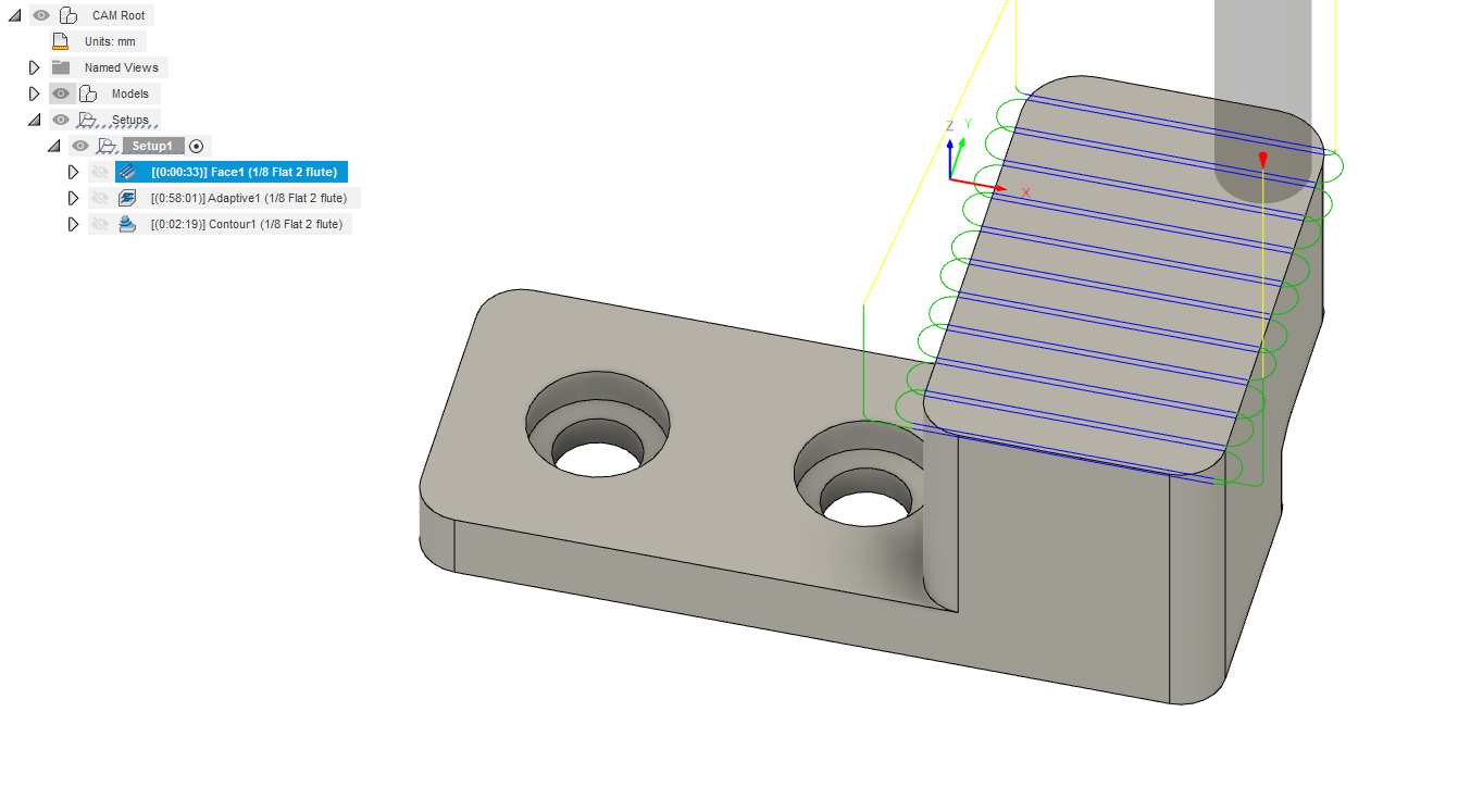
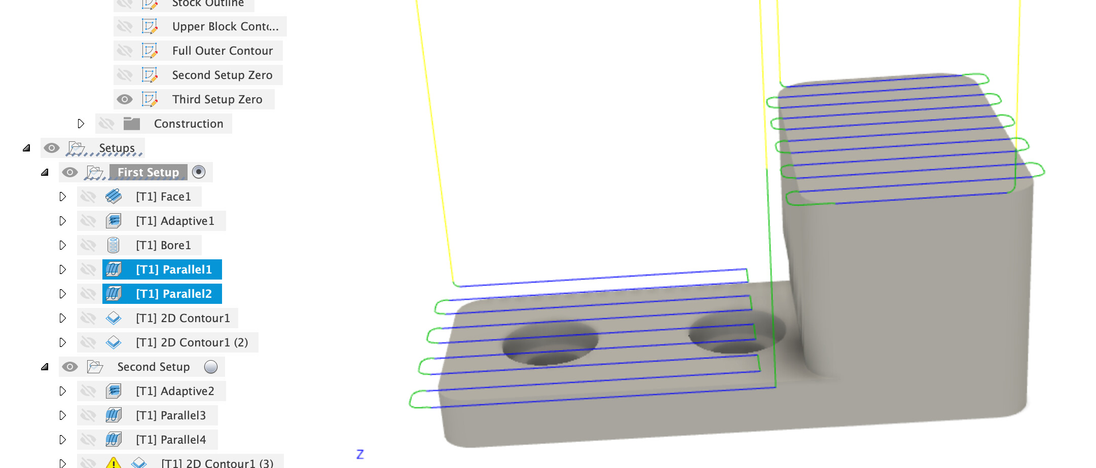
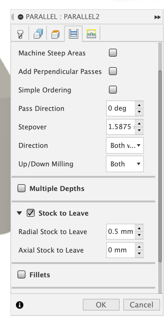
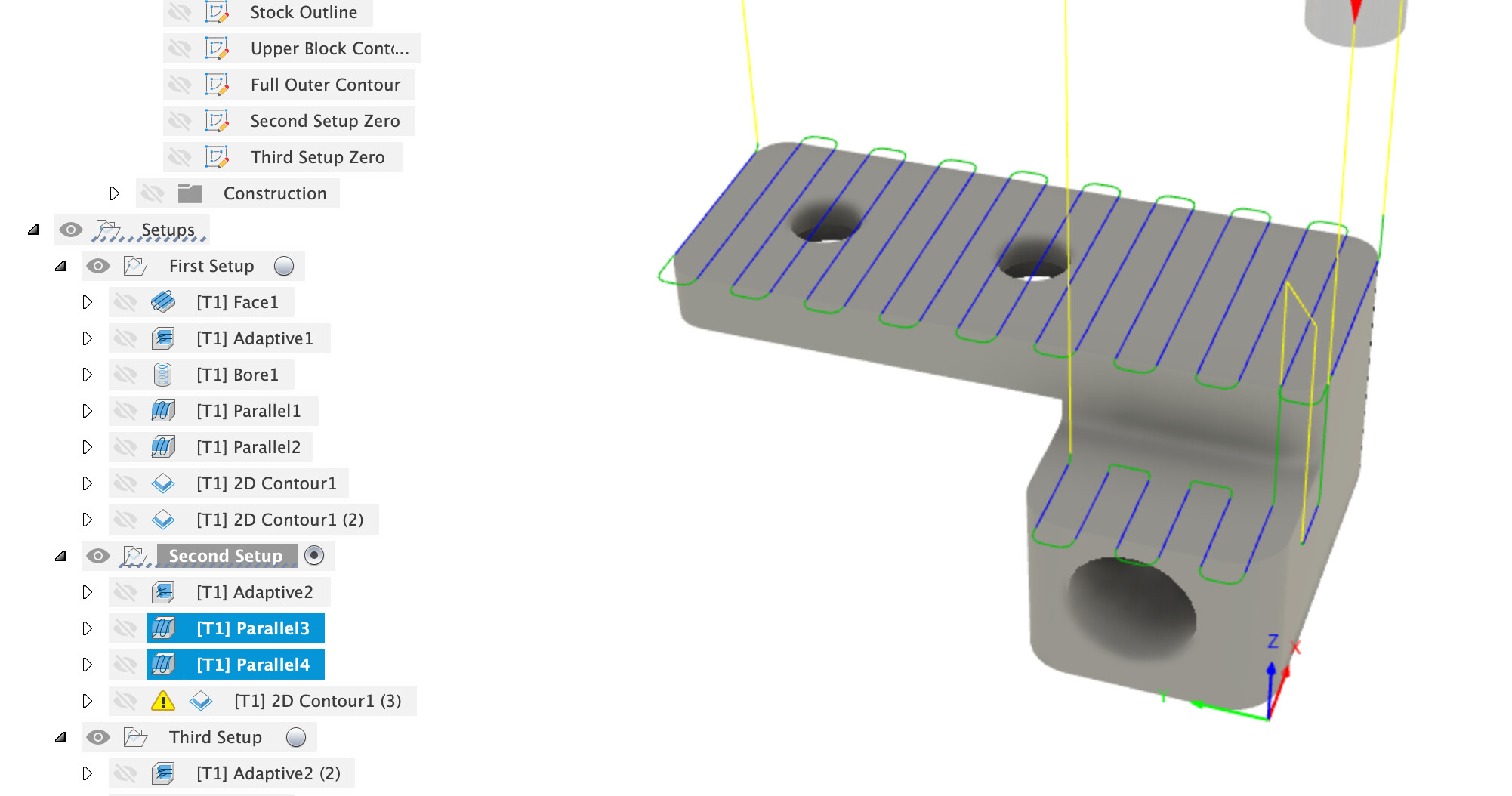
Then a couple of parallel toolpaths giving us a finish on the flat surfaces.
Note the lower parallel leaves 0.5mm radial stock to leave to avoid heavy engagement on the wall of the upper part.
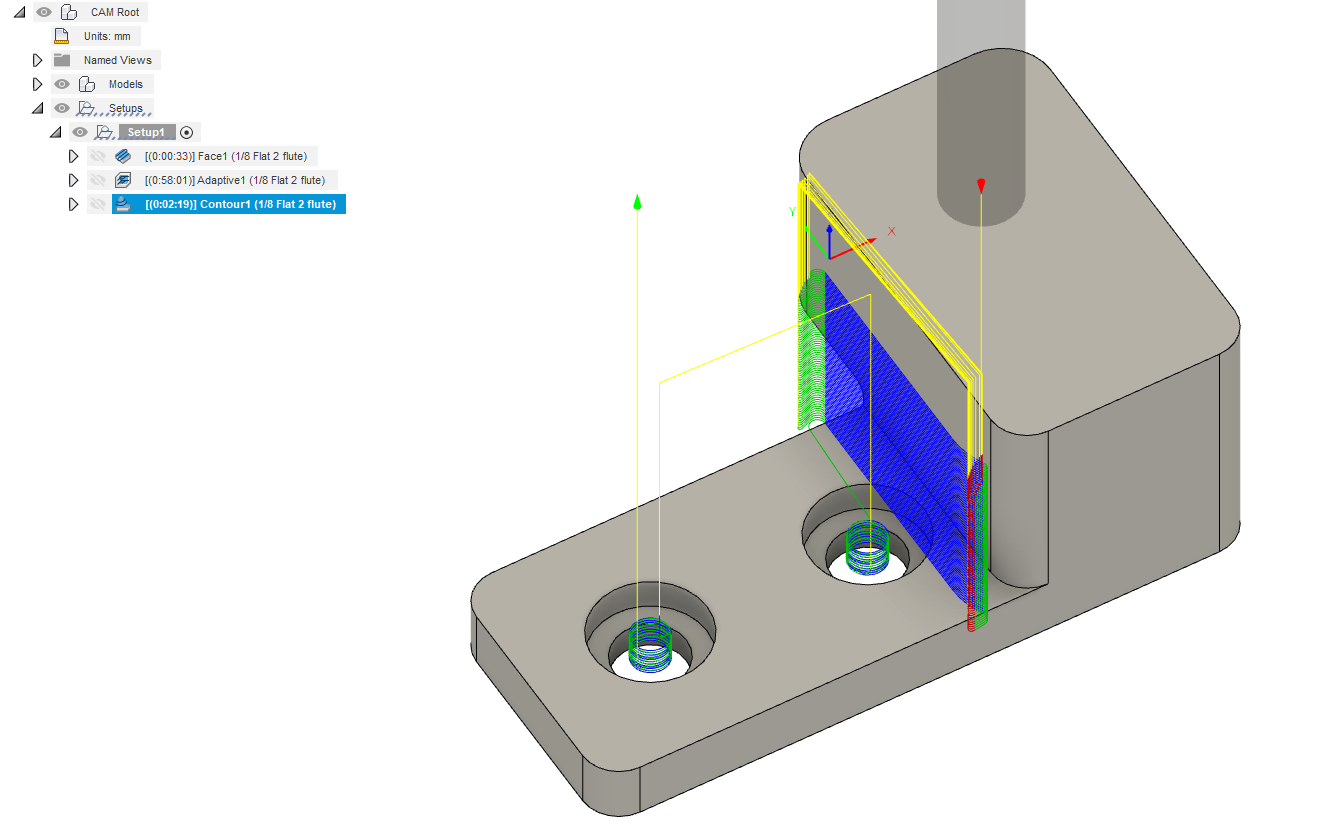
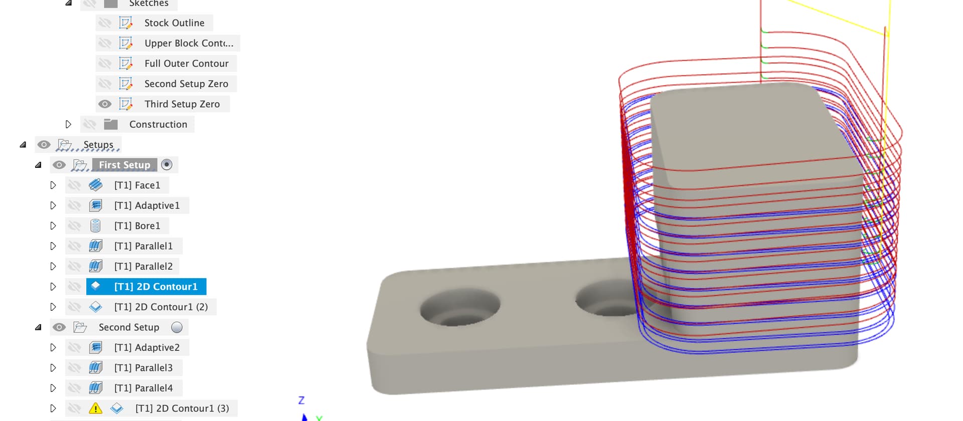
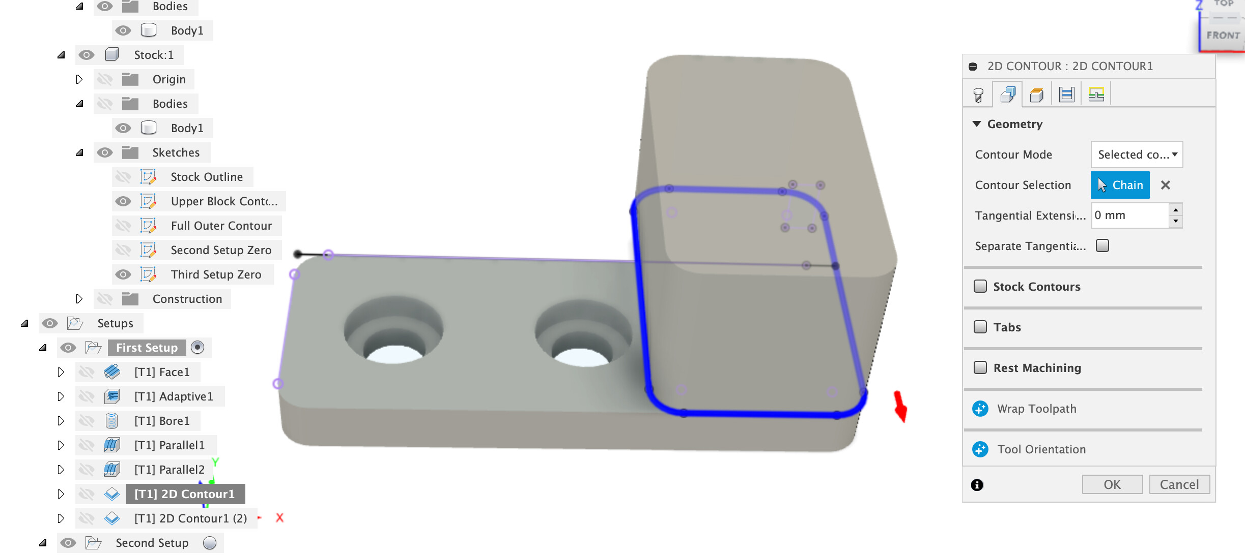
Then a contour walking down the upper block of the part (no idea what depth per pass for this on a Nomad). This is achieved by creating a sketch on the top face of the lower flat and projecting the upper block into the sketch to give a selectable continous path.
Next we need to walk down the sides again to cut the full outer contour, another projection into a sketch is used for this. Note there is a nasty square corner here which will give a heavy engagement and might chatter and mark the part.
This has done all the work we want to from this side, we left a nice shelf all the way round the base to make workholding easier.
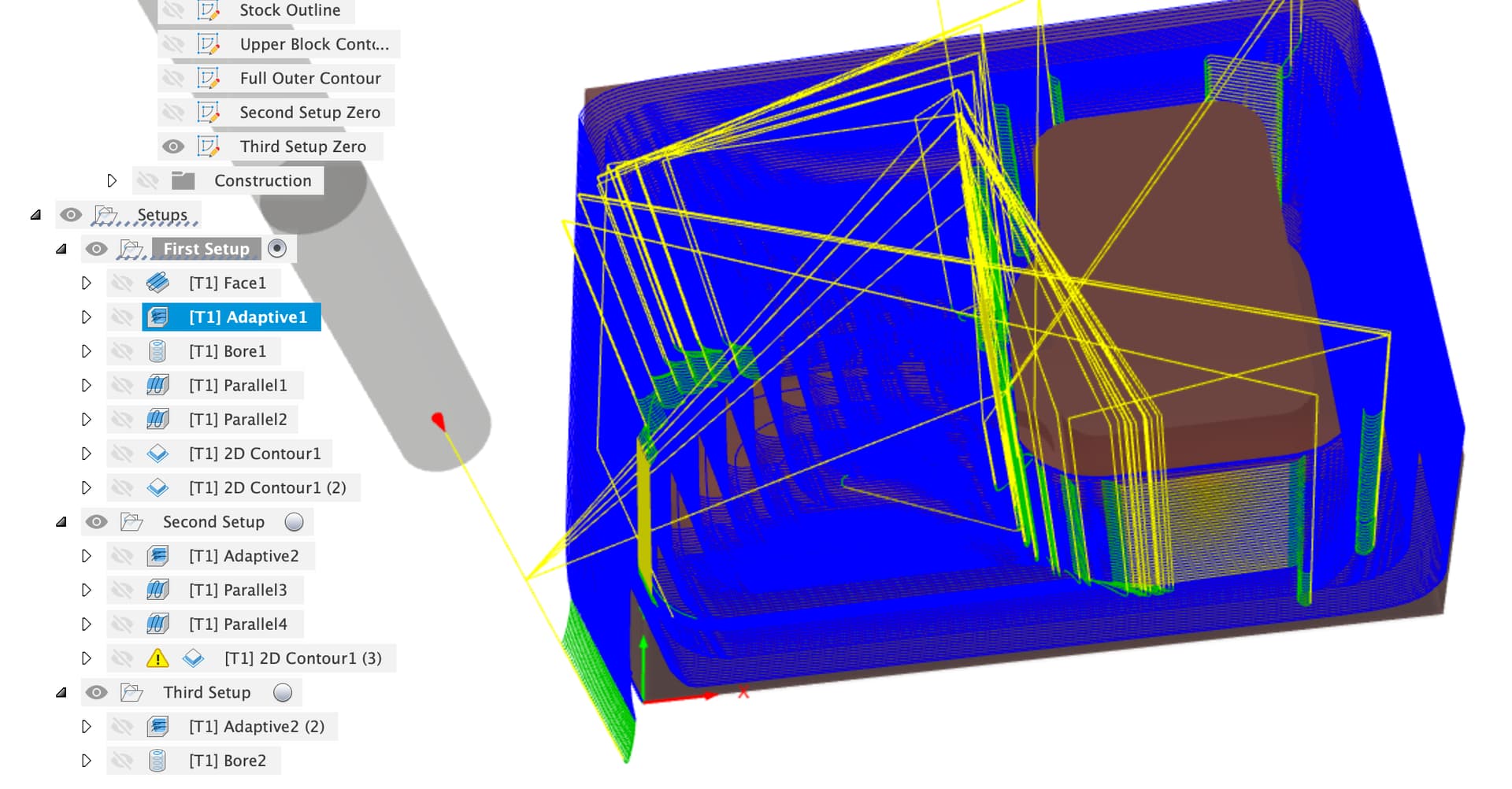
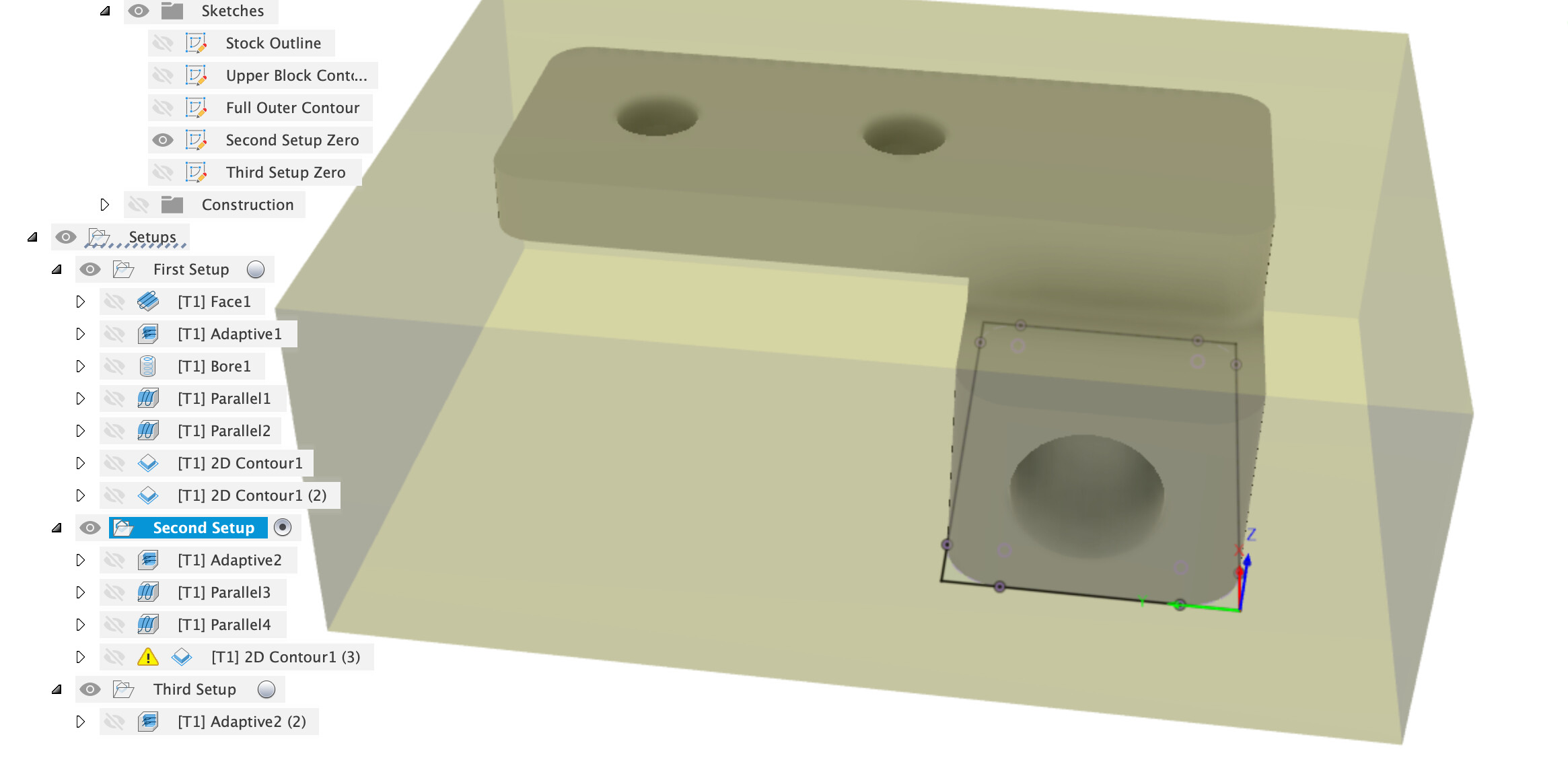
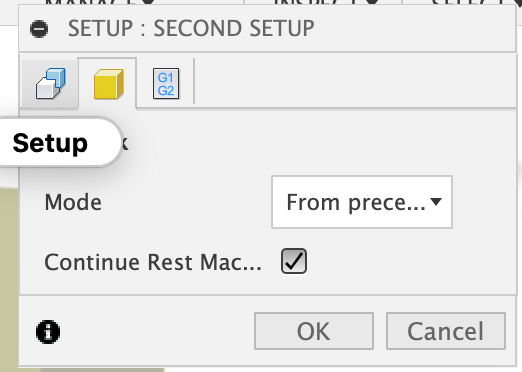
Second Setup
Now we need to flip the part over, and you need to decide how to re-indicate your zero to get the part to line up. I’ve assumed a vice that you can indicate off the jaw for this example. We’re using stock “from preceding setup” with “continue rest machining”
Note the zero and axis orientation, the zero point is in the sketch “Second Setup Zero” and uses the machined faces from setup 1 for alignment. Note this zero is the machined finished face from the first setup.
First job is another adaptive to clear out the big shelf we left in op 1.
Then a couple of parallels to give finish faces (same radial stock to leave trick as before on the lower face)
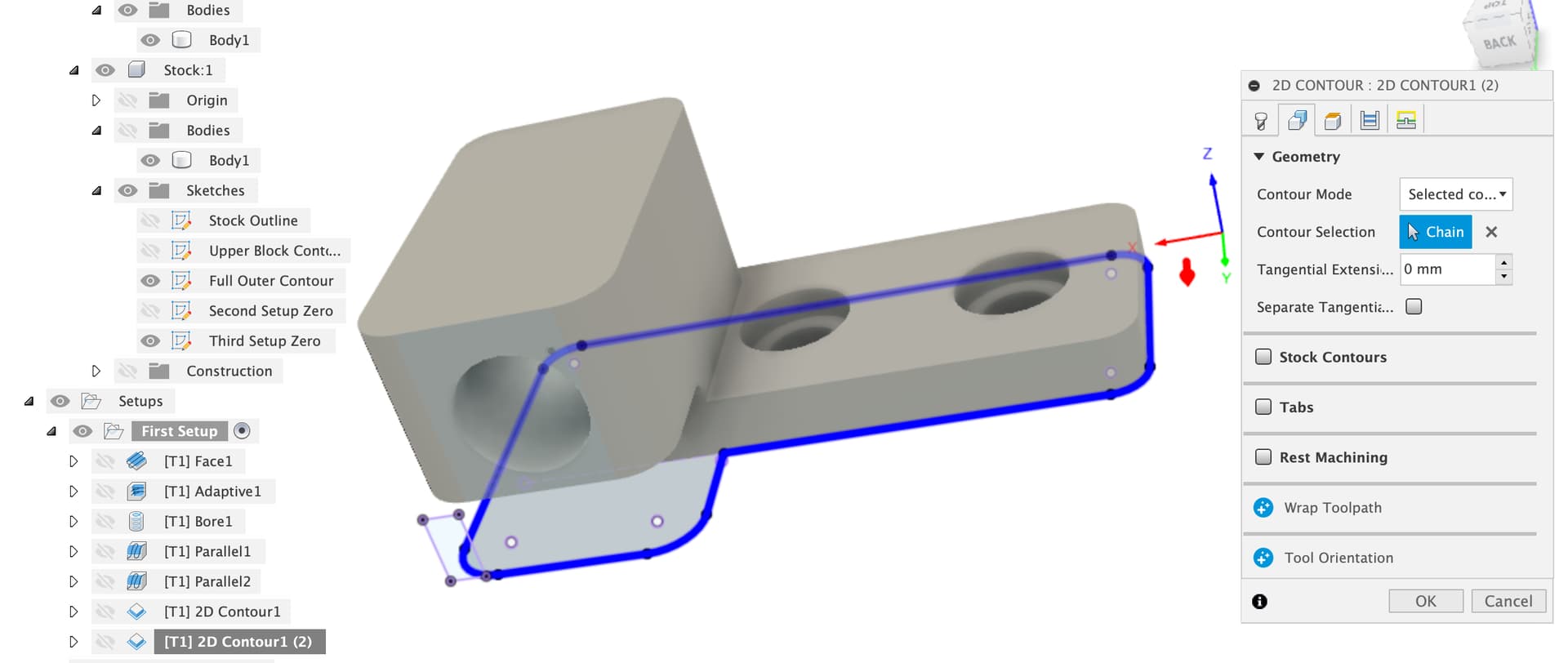
To cut along the remaining edge we couldn’t reach from the other side, a contour, again using a projection into a sketch
Here’s the main part we can’t machine, if we go all the way down to the lower face we won’t give the fillet in your design unless you use a ball nose mill. I’ve left that part rough for you to figure out. I also left out the fillet on the outer corner as that may, or may not line up perfectly and is easy to hand finish.
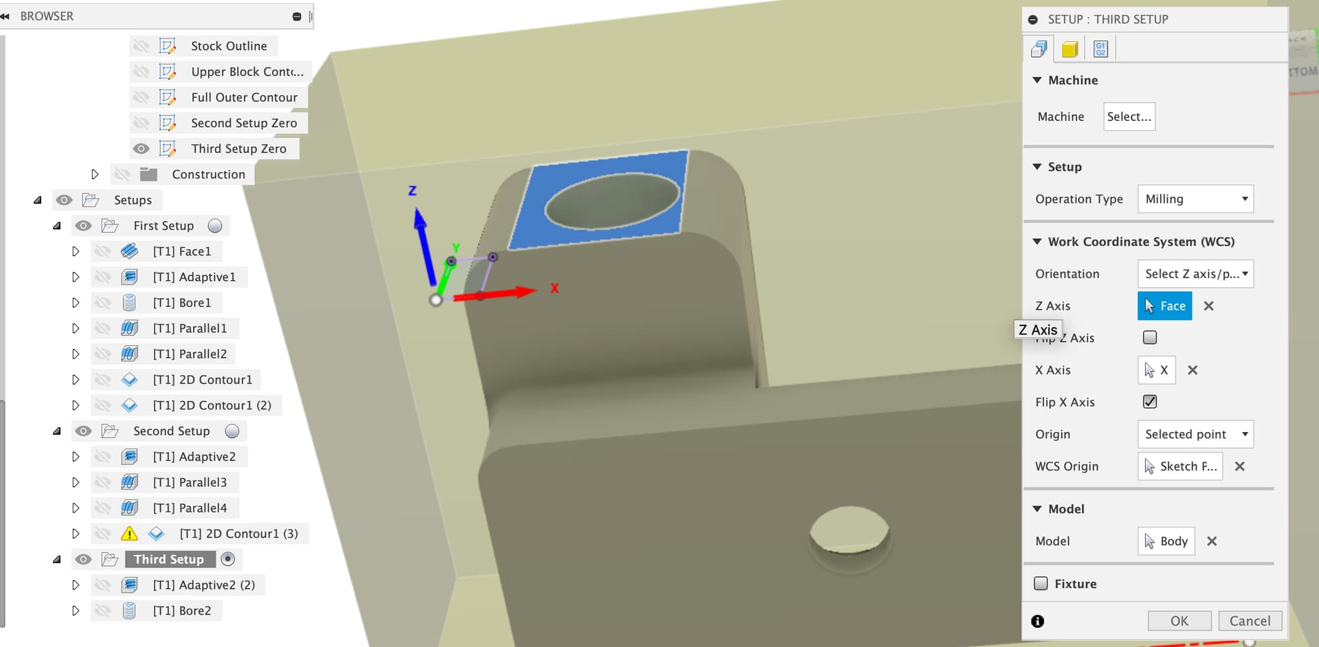
Third Setup
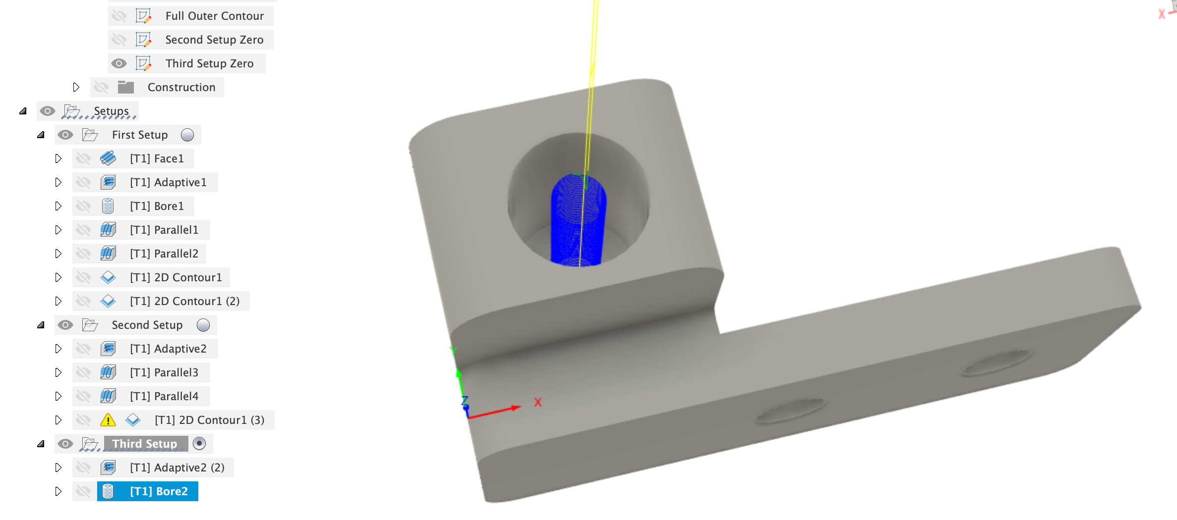
Finally, the third setup to put the large hole in the mount.
Warning These operations are quite deep and will likely have chip-clearing issues needing lubricant and / or air blast to avoid gumming up your cutter.
The Z plane is the face of that block, another sketch is used with geometry projected to provide a zero we can indicate to.
Ops in this setup are an adaptive clear
Followed by a boring op to finish the walls of that hole
Which doesn’t give the bottom feature you have in the hole.
All in this part is quite a bit more complex than it looks to machine, you need 3 setups and still don’t have the 3mm holes in the flat part. Re-zero-ing between setups will take a little practice too, don’t expect to get that right on the first try and there are some deep holes close to cutter diameter with chip clearance issues to beware of.
HTH