Help with Pocket and Contour

So I’m using the latest beta version (608). Been trying to cut out a pocket and then make a piece to fit into the pocket using the contour. They seem to be off by .03-.04" or so. So I decided to create a simple file with just one pocket and one contour of the exact size. the CC file is attached. I’ve also attached the gcode. I’m just using a 1/8" bit. It’s just cut on a junk piece of wood… The first picture is the 2 cuts. The second is the inside of the pocket (roughly .81"). The third picture is the actual piece cut by the contour (using the outside/right).

Since I was doing an odd SVG shape, I decided to try the same thing with a square 1" so I could actually measure it. The pocket is exactly 1" but the contour (outer/right) is the one that is off.

So the issue seems to be how I’m doing the contour cut… Can anyone help me or is this a bug in the software?

Thanks everyone


test-dimensions.c2d (27.9 KB)
test-dimensions1.nc (64.6 KB)

The G-code file is fine, both the square pocket and square contour, the coordinates in those toolpaths grant a theoretical dimension of 1" in both cases. So it’s not the software.

The pocket is cut from the inside out, with a stepover of 0.06", so when the cutter makes the final outer pass in that pocket (at each depth), it only has half the cutter diameter engaged in the material.

The contour cut on the other end, has the full cutter engaged at all times (by definition / slotting).

What is the length of the 1/8" endmill you used and what was the stickout when you did those cuts ?
It could be tool deflection. 0.04" difference in dimension is 0.02" deviation on each side, which is a large-ish tool deflection value, but not impossible depending on the setup (and how blunt the endmill is, potentially)

To either confirm or rule out this hypothesis, you could rerun the contour cut at half the depth per pass and/or minimizing tool stickout, see if it changes anything in its final dimension

The other usual culprit is the tool not actually being exactly 1/8" in diameter, but the error would show on both cuts (i.e. the pocket would be undersize, while the contour would be oversize, if the cutter was slightly less than 1/8"), so this is probably not it here.

1 Like

Thank you Julien - so I tried to test your hypothesis… I cut 4 more squares. One with a .03" depth per pass, one with .02" depth per pass, and then one with .01" depth per path. All three were still .97" when I measured them. I’m using a whiteside 1/8" bit that has .75" depth of cut. I also made sure it was stuck up as high as I could into the router.

So to test one more time, I cut another square, but this time using the 201 bit that shipped with my Shapeoko, figuring it would be .25" in Diameter and sturdier. I also made sure it was as high up into the router as possible. Same thing, still measured .97"…

I’ll try to inspect the g-code myself as something just does not seem right. Is there any tricks to doing this? I kept this file simple with just 1" squares.

Thanks as always - your help, expertise, and willing to help are second to none.


test-dimensions-try2 Julien.c2d (410.1 KB)
test-dimensions-try2 Julien-2.nc (10.8 KB)
test-dimensions-try2 Julien.nc (39.0 KB)

Can you try creating a pocket around your square and then doing a finish pass to get it to the final dimension?
I don’t use Create, so I’m hoping the file here shows what I mean.
testOneInch.c2d (66.9 KB)
If that one is better, then I think you’re just experiencing deflection. The good thing is that it won’t scale.

1 Like

Pretty sure the G-code is fine. What I did to check is

  • open the file in ncviewer.com
  • on e.g. the square contour, click in the preview window on a specific point in the toolpath
  • if you then click on the highlighted line on the left pane and use up/down arrow, you can navigate through each line of G-code, and see the tool move in the preview window
  • locate the line corresponding to the straight move that is the right side of the square, and make a note of the X value
  • navigate further down the toolpath until the tool is at the straight move on the left side of the square, and make a note of the X value there
  • subtract the second X value from the first one
    • for the contour toolpath, the endmill is moving on the outside edge so you need to subtract an additional tool diameter (technically subtract the radius twice, once for each side) to the result.
    • for the pocket, the endmill is moving inside the vector so need to add the the tool diameter

I did that on your file and got exactly 25.4mm (since the file is generated in mm), so exactly 1".

Your tests seem to show that it’s not deflection from cutting forces, but Neil’s test still makes sense to rule that out for good. If this is not it, I would say

  • check how much the tip of the tool travels when you jog it in the air by 1". A caliper would be good, but even with a tape measure you should be able to see if 1" movement results in 0.97" actually travelled.
  • is there any play if you grab the shaft of the endmill and try to wiggle it around while the machine is turned on (but router off, obviously :sweat_smile:) ?
  • if you do the 1" air jogging & measuring, also try to check whether if you do a return move to the original position, it does return exactly to the original spot.
1 Like

Thanks Julien and Neil. So I tried Neil’s test this morning - drew a 1" square, created an offset to be 1.6" square and then pocked it out using the 201 1/4" bit. It came out at .98" square, so got a tiny bit better. So does this mean it’s deflection? I’ve attached a picture of the Z-axis. Should the router be mounted higher? Right now, it’s all way down… What else do I do to minimize deflection?

2 Likes

The router all the way down like this is its “normal” position, so that’s fine.
The “deflection alone” hypothesis is getting less and less likely.
What about the last three bullets points I mentioned in my previous post ?

1 Like

I’ll try that a bit later today - But given my pockets were exactly 1", I was assuming something must be right and it had to do with the contour cuts. I might also try a 4" square to see if the issue scales or if it’s just off by 0.03". Thanks again for the help!

Can you try a similar test with the pocket?
Make a pocket like 25mm square, then do a contour to get the last 0.4mm.

2 Likes

There’s a difference in how the machine cuts between climb and conventional cutting, and I’ve found the best thing for accurate dimensions is to leave a roughing clearance and take a finishing pass.

OK - so I tried the air test - ran it 30 mm, measured it exactly to 30mm, then back. So no issues with that.

So if it’s deflection at all, I decided to try to raise the router up about an inch (vs. being all the way at the bottom). My thinking is this could help deflection. Reran the tests and got closer to .99", so I think that’s good enough for me. But I will now keep in mind the amount of material removal for contour vs. pocket, which makes more sense to me now.

Thanks everyone for the super prompt support and willingness to help people out. This forum, along with Carbide 3D support, are truly amazing.

1 Like

Interesting. I would now say “go and check all your v-wheels”, the four on the back of the Z-plus AND the 8 on the left and right side of the X/Z gantry. And make sure they are all night and snug against the rails.

If raising the router 1" significantly reduced deflection (so, not tool deflection after all, but router/axis deflection), and since it was not quite normal to have that amount of deflection in the first place, I have a feeling there may (still) be something a little loose at the mechanical level.

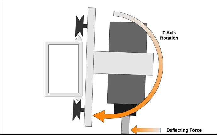
@LiamN has a fantastic thread on this, it’s a super long post (and a great read), but look for the part with that pic:

image

Or just proceed with milling stuff, that works too :slight_smile:

1 Like

Yep,

Before my outbreak of upgrade-itis I found that stacking the workpiece up on some extra spoilboard to reduce the leverage and keeping my router higher worked well to reduce deflection.

1 Like

Something that you maybe overlooking. Even though you have 1/4 endmill and technically its supposed to be .250 Most of the time the endmills are always a couple Thousandths smaller, but if you are .251 or .2515 this would account for your dimensional differences.

This topic was automatically closed after 30 days. New replies are no longer allowed.