Backlash, Deflection and Vibration

Firstly,

Thanks to @Julien @gmack and @spargeltarzan for their comments and assistance, quite a few poor assumptions of mine were corrected during the process of this investigation and write-up. Obviously the remaining mistakes are mine alone.

Here’s all the content below as video on YouTube, some of these things are easier to explain with the video, it’s broken up into 3 videos

A zip file with the machine deflection models, this text as a single PDF and a word doc with the maths I used for the simple deflection models;

Backlash Deflection and Slack.zip (2.1 MB)

Chapter 1 Intro & Summary

What?

I’m looking at the various elements of deflection and backlash measurable on my Shapeoko. From the measured behaviour I’ll attempt to localise and explain the main sources of deflection and backlash and fit a simple model to them to explore the behaviour.

The intent is to understand where this unwanted motion comes from, to better manage the machine and determine what benefit, if any, various potential upgrades might provide.

This is based on a single sample machine, my XXL with HDZ axis; the model is deliberately simple and may raise as many questions for you as it answers but hopefully this is a step along the way to a better understanding of the machine and how best to use it.

Since the announcement of the Shapeoko Pro there has been considerable interest in the changes made to that machine. So, I’ll also take a look at those changes and which of them might be worth replicating as upgrades to a Shapeoko 3.

Doing this, I have spent quite some time taking a lot of rather boring measurements. I initially just wanted to answer the question of whether belt tension affected backlash, but the task quickly snowballed. Each measurement seemed to pose at least as many new problems as it resolved and in many cases I had to go back and re-measure previous elements. Hopefully, this means others will be able to spend their time on more interesting things instead. I have also done some maths but there’s no need to follow, or even read, the maths unless you want to.

All the deflections discussed here are < 0.4mm or 15 thou, these are small numbers and the machine is capable of work much more precise than this. That does not however, mean that we don’t want it to be better or do the work faster.

We will look at;

  • What are deflection and backlash and why do we care?
  • How deflection, vibration and resonance are connected to each other
  • Deflection in the baseboard
  • V Wheel deflection
  • Drive belt deflection on the X axis and how this varies with position
  • V Wheel friction and how this produces backlash
  • Y axis deflection behaviour and what affects this

The deflection measurements are all taken using a 50 Newtons of Force applied to the spindle (approx. 5kg or 11 lb f). This value was chosen because it represents a large enough force to cause measurable deflection but is still below the stepper motor breakaway torque. This is larger than the average cutting forces most users will produce on a Shapeoko, however, the vibration forces once resonances are triggered, can be much larger than the mean cutting force as we build up energy in the vibrating mass.

To understand the machine behaviour it’s important to recognise that the total deflections at the spindle are the sum of the individual deflections of a series of components. I will attempt to break these down into sensible parts and represent their individual and cumulative contribution. For example here is the left/right deflection on the X axis.
The graph shows the sum of the X deflection building up as we move from the frame to the cutter via;
• The Y rails sideways deflection
• Y plate deflection allowed by the V Wheels
• X belt deflection (measured at HDZ Side)
• Z carriage wobble on X rail (measured at Spindle Side)
• Z carriage rotation about X rail (measured at the Collet)

Summary

My measurements suggest that there are substantial differences in the achieved rigidity, backlash & vibration performance between the SO3 and the XL and XXL machines. Also, the model indicates that these do not scale as you might expect between the machines, the XXL is a very different machine to the SO3. If, like me, you’ve seen how SO3 users can cut materials like Aluminium and wondering why you can’t achieve the same on an XXL, it’s not just your technique;

  • Deflections on the XXL are much larger than the SO3, on the X beam for example, 0.3mm on the SO3 become 2.2mm on the XXL for the same load, just due to physics.
  • The belt deflections and backlash approximately double on the XL and XXL longer axes.
  • The V Wheel wobble should be the same between machines but makes a much larger, by proportion, contribution to overall deflection in the small SO3.

I found some cases where tuning the machine is directly trading achieved accuracy for cutting speed. For example, increasing V Wheel tension to reduce cutting vibration directly increases the backlash on that axis.

The belt deflection behaviour varies substantially not just with the belt material and machine but with the machine position in X and Y, this is more significant on the XL and XXL machines. There are graphs later-on showing how these and other deflections interact.

As in any machine, the deflections and backlash in the machine allow for vibrations and resonances to develop when cutting. The relatively large deflections per unit force, coupled with the quite low damping of the machine allows for large resonant vibration amplitudes to develop quite easily. Once these resonances develop, It can take large changes in cutting parameters to quell them and to many users this may represent the limiting factor on cutting speed.

These vibration modes are also likely to vary substantially between the SO3, XL and XXL machines, with lower frequency vibration modes occurring on the longer axis machines.

I found that the calibration for steps / mm of the machine is much more complex than it at first appears to be. The actual distance moved per step varies with at least the following;

  • Variation in V Wheel rolling resistance with V wheel preload
  • Variation in rolling resistance as the machine moves caused by accumulated chips and dust on the axis rails and wheels as well as wear or damage to the wheels
  • Variation in belt forces with axis position
  • Possible small variations in the precision of the belt tooth spacing

Belt Tension

In a previous video I looked at belt tension, how to measure it and what sort of tension is desirable. One of the open questions from that work was whether increasing belt tension usefully reduced backlash in the machine.

This analysis suggests that no, increasing belt tension above the base minimum does not further reduce backlash. in light of this and considering the rated radial loads on the stepper motor shafts, here’s an updated table for belt tension frequencies;

Shapeoko Pro

When viewed through the lens of these XXL deflection measurements, the upgrades on the Shapeoko Pro make a lot of sense.

  • The reinforced base and spoil-board
  • The linear rails vaccine for the V Wheel problem
  • The slightly improved belts (Note that the return from steel core to fibreglass for belt reliability absorbs some of the benefit)
  • The Y axes braced against the base
  • The milled front and rear frames

Those changes deal with many of the deflection sources identified and in pretty much the order I would upgrade my machine too.

Order of Upgrades

Speaking of upgrades, the next question is, what upgrades might I want to do and in what order? It is clear that some upgrades will deliver a lot more benefit for the cost or effort than others. My non-negotiable top upgrade is replacement of the old belt driven Z axis with either the Z+ or HDZ. I consider this to be an entry point for anyone concerned with deflection on their machine.

The severity of the issues and therefore the order of upgrade, depends upon which size machine you have, some issues are the same across all sizes and others vary substantially. This table proposes an approximate priority order for upgrades based on the measurements and models. You may well not agree with it, but it’s a place to start arguing from.

17 Likes

Chapter 2 Deflection and Vibration

Why do we care?

There are two main reasons to care about deflection and backlash in the machine.

Ultimate accuracy

Whilst we can achieve some pretty-impressive accuracy with a Shapeoko, this frequently involves several rounds of cutting, measuring, fiddling with the CAM to incrementally approach the final dimension we require. This can be somewhat time consuming and make our CAD / CAM models more complex as we make the compensating adjustments.

If we take roughing passes to cut the bulk of the material and finishing passes to get to final dimension our deflection due to cutting load is minimal in the finishing passes. It should then only be backlash that prevents us from approaching the step size limiting precision of the machine.

Cutting speed

The second concern is cutting speed, when we cut, we generate forces, the machine needs to resist these forces and keep the cutter and workpiece where they are supposed to be. Deflection in the machine affects the cut, but more significantly, allows vibration to develop. In particular there are modes where the machine tends to resonate, these can build a positive feedback loop where the vibration periodically varies cutter engagement and therefore the cutting forces, reinforcing itself and increasing the amplitude.

In practice the impact of vibrations and resonances can vary from poor finish through breaking cutters, damaging the workpiece, pulling the workpiece loose or even damage parts of the machine.

So, deflection primarily limits the speed at which we can cut and potentially the quality of finish whilst backlash primarily limits our final accuracy.

Backlash, Slack and Deflection

First, what do we mean by the terms backlash, slack and deflection?

Backlash

Backlash is lost movement in the linear motion system where we request a change of direction. For a typical rack and pinion, ballscrew or leadscrew driven linear motion system we can visualise backlash as being like carrying a bowling ball in a box.

The ball is broadly constrained to go with the box, but each time we reverse direction we have to move the box far enough for the ball to hit the opposite wall before it follows the box change in direction.

On the Shapeoko backlash occurs through a different mechanism and presents slightly differently. Here is backlash on the X axis, we are measuring close to the belt to reduce the influence of other movements such as V Wheel deflection.

Slack

Slack is very similar to backlash in that it gives a range of positions the machine may be when no force is applied. The distinction, for our purposes, is that slack occurs not due to the drive belts but simply through slack in the mechanism such as the V Wheels which allow movements not controllable by the motors and belts.

Deflection

Deflection is where the machine moves from the requested position due to forces encountered whilst cutting (or by the operator). Some of this deflection comes from flexing parts of the machine, some of it comes from stretching the drive belts.

When cutting deflection can cause a couple of problems, first it can cause cutter engagement to be larger or smaller than we intended, affecting the cutting load. Second, and more of a problem on a light machine like the Shapeoko is that the machine can start to vibrate and resonate with the deflection of the cutting loads.

Millalyzer single flute
(screen capture from Millalyzer application)

The graph shows some example cutting forces for a 6mm single flute cutter in 6061 Aluminium making a Shapeoko sized cut at 22kRPM, each rotation there is a spike of 32 Newtons on the cutter but the average forces are quite low. For the range of speeds and cutters commonly used on a Shapeoko the frequency varies from around 200Hz to 1.5kHz, this is a broad range of input to excite vibration and resonance modes in the machine. Here’s another for a 3 flute cutter showing the three impacts of teeth on the workpiece per revolution

Millalyzer three flute

Deflection, Vibration and Resonance

The major limit to cutting speed on the Shapeoko is vibration of the spindle or workpiece induced by cutting forces. It is rare to run out of spindle power or torque before encountering one of these vibration modes. Most users have experienced this when pushing their machine into too heavy a cut where small vibrations rapidly build up into large vibrations which are then difficult to suppress. When examining this system, not all our deflections are equal when it comes to vibration.

It’s worth taking a look at the vibration and resonance issues before moving into the deflection and backlash as these are the primary issue arising out of the machine deflections.

Basics of Vibration

Before discussing the vibrations in machining let’s take a moment to define a few terms and describe what part they play. To think about the vibrations, consider a simple mass on a spring, like a vehicle on a suspension spring.

As the mass moves, the spring compresses and extends. The spring wants to be in the ‘middle’ so it works to reverse the movement. There is a frequency at which each mass & spring combination likes to move. The lighter the mass or the stronger the spring the higher that frequency.

There is usually some sort of damping taking place as well to reduce the movement. The greater this damping the faster the mass will stop moving when the force is no longer applied and the smaller the maximum amplitude of the movement if we continue to excite the mass at the resonant frequency. This is why old cars bounce up and down quite easily but new cars with working shock absorbers don’t.

Chatter, Vibration & Resonance

In traditional milling machines the phenomenon of chatter is relatively well understood. Machine, tool and workpiece deflections interact with cutting forces to excite a resonant vibration in the machine, thus producing the characteristic ‘chatter’ sound and other issues. Various rules of thumb exist to avoid or manage chatter such as keeping tool deflection due to cutting forces below 0.001” or plotting stability lobe diagrams of your machine and tool combination.

This is not a simple process and there is a range of ways in which your machine can vibrate in these undesirable modes and affect the cutting performance.

At one end we have high frequency vibrations, in the range of our high speed spindles’ rotational speeds where relatively small masses, such as cutters or parts of the workpiece, vibrate on very stiff ‘springs’ such as the deflection of the carbide cutting tool or a wall in the workpiece.

At the other end we have lower frequency vibrations where relatively heavy parts of our machine assembly vibrate against less stiff springs. One example of this is the Z carriage and spindle assembly vibrating on the drive belt ‘spring’.

Vibration Interacts with Cutting Forces

When the machine is cutting we have a series of things going on, the cutter is rotating at a target speed, being fed through the workpiece at a feed rate and has some depth (axial) and width (radial) of cut, all adding up to the cut we are taking (or trying to take).

Once this cut starts, the cutter produces forces between the spindle and workpiece as it cuts, these forces on the cutter are shown, simplified, for a climb cut below. These would be inverted for conventional cutting.

These forces inevitably deflect the cutter and workpiece some amount. When the cutter deflects away from the cut, as caused by the cutting forces above, the engagement reduces and thus the cutting forces. This machine then tends to spring back into the cut. If the workpiece deflects we have the same outcome.

When the machine swings back and deflects the cutter further into the cut, the engagement increases and the cutting forces increase, in this case pushing the cutter back away from the cut.

So we have a system where the deflecting forces are affected by the deflection. If this happens at a frequency at which the tool, workpiece or machine can resonate then we have a positive feedback system which can rapidly achieve a large displacement. The problem with these resonance modes, especially when they have little damping, is that once excited they can be hard to escape. They can develop a lot of energy and will continue to feed themselves with energy whilst the cut continues.

There is a famous video of the Tacoma Narrows bridge demonstrating why resonance can be bad.

Worse, vibrations also leave variations in the cut surface which may trigger the same vibration on the next pass of that cut. Returning to our vehicle analogy, once the road starts to washboard, it can be very hard to get away from that vibration.

Shapeoko Resonance

There are various well understood methods and tools for larger machines, from test cuts through to specialised test hardware which measures the cutter and machine resonances. These identify problem frequencies and provide feeds & speeds or charts to avoid them. This knowledge is less well developed for ‘hobby grade’ machines.

So, what sort of frequencies might we expect on a Shapeoko? For vibrations triggered directly by the cutter rotation at spindle speeds we’d expect to see frequencies somewhere in the range of 200Hz to 2kHz.

Cutter Speed Frequency

Vibrations at these frequencies are generally not visible to the naked eye, when you see a speaker cone moving it is bass frequencies, not midrange.
However, in addition to simple spindle frequency vibration we also have the lower frequency modes which are not directly responding to spindle speeds but instead build up in the machine as resonance. Going back to our simple mass on a spring, we can do some simple calculations to find out what sort of frequencies we might see on the Shapeoko.

Let’s take one element of the Shapeoko, the Z carriage and spindle and isolate it from the rest of the machine. We will assume the spindle is deflecting left to right on the X axis rail opposed by the spring of the drive belt. Taking the values from my machine we get an approximate resonant frequency of 22Hz which is consistent with the visible resonance modes I have observed on my machine.

This vibration has some damping, primarily the rolling resistance of the V Wheels. This is perhaps another reason why high V Wheel pretension seems to help the machine?

To try to improve this performance, we might add mass, say a water cooled spindle instead of a trim router. Unfortunately, the outcome is more complex. The additional mass lowers the resonant frequency and increases the amplitude when the resonance does occur. However, at frequencies above the resonance it will reduce the amplitude of vibrations.

Digging a little further we find the source one of the large differences between the SO3 and the XXL machine. Taking the X beam rigidity for the XL and XXL (which is addressed later on) and using this as the spring for the Z carriage assembly vibrating backward and forward;

We see that we have a resonant frequency of about 34Hz. However, if we take the standard size SO3 machine with the shorter X beam, we have a much smaller deflection for the same force;

This higher spring constant gives a resonant frequency almost three times higher than the long X beam and suggests that the trigger feeds and speeds for this mode would be quite different on the standard size machine.

Deep vs Wide Cuts

One common observation about the both the Shapeoko and Nomad machines is that to achieve the maximum cutting rate (MRR) one should use a shallow but wide cut instead of a deep but thin cut;

We know that in a resonance mode we have feedback between deflection and cutting force. Taking two cuts with the same cutter engagement, one deep, one shallow. If we allow both cuts to deflect horizontally by the same amount, we see that the shallow cut only sees 20% extra engagement whilst the deep cut sees double the engagement and therefore cutting force.

Also worth noting here is that with cutters with a helix angle (i.e. not straight flute) the deeper cuts will also create significant vertical forces to excite the coupled Z and Y nodding deflection (again more on that later).

Shapeoko as a System

We can look at the main parts of the Shapeoko as a connected system of masses and springs.

Here is a simplified diagram which illustrates some of the main components in which I have measured deflection. On the left we have cutting which creates force between our workpiece and cutter, the forces and their resulting deflections and vibrations then travel to the right, through the components of the machine until we reach the mounting base.

This system is unfortunately quite complex to model and analyse, however, modern computer simulation tools can provide some excellent insight into this. Hopefully somebody with those skills will have something to say about that.

What we can do now is look at this system and identify that we have several large sources of deflection close to the cutter and that these are likely to be our major targets to reduce slack, improve rigidity and, if possible, increase damping;

  • Z axis and spindle rotating due to V Wheel radial deflection
  • Z axis and spindle nodding due to V Wheel axial deflection
  • Z axis and spindle translating left-right against belt tension
  • On the XXL machine, the bouncy baseboard
16 Likes

Chapter 3 Deflection Measurements and Model

First Suspect – Baseboard

Our first suspect for deflection is the notorious baseboard of the XXL machine.

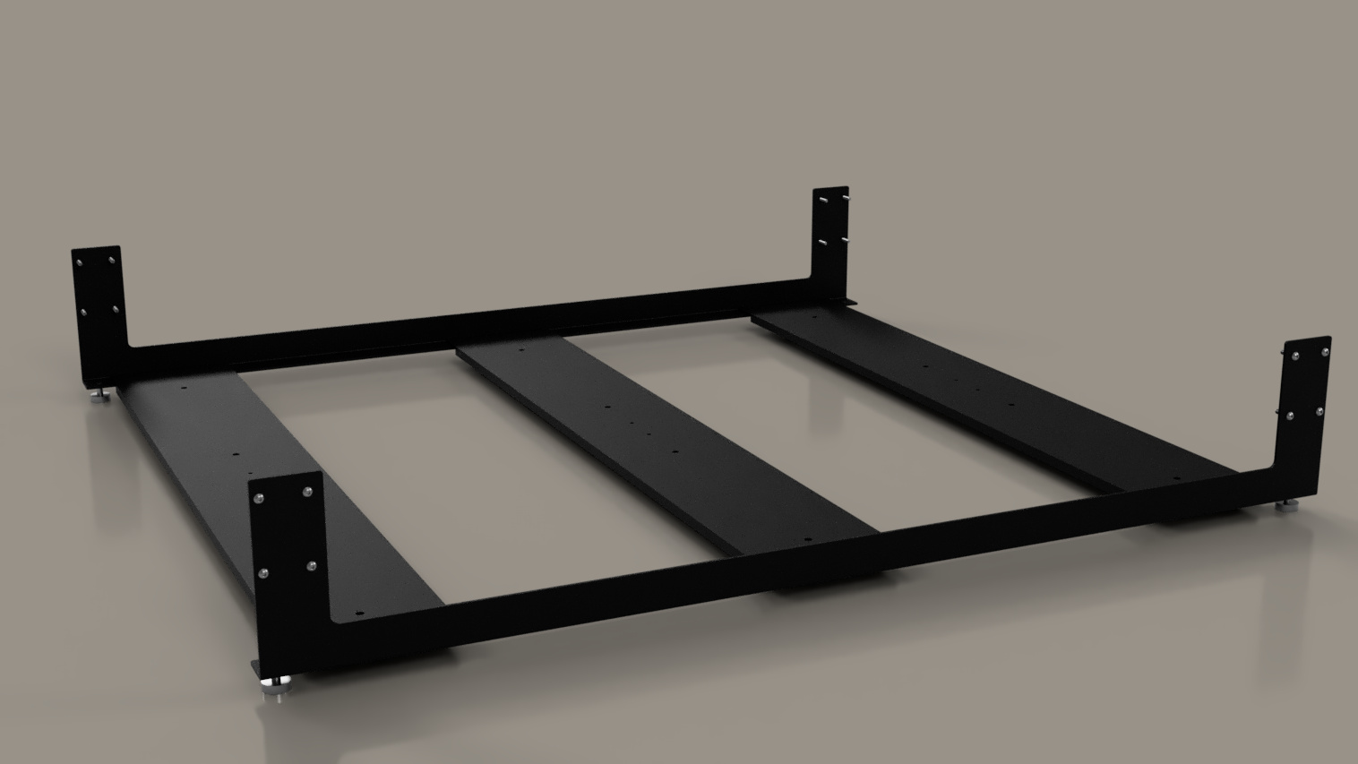
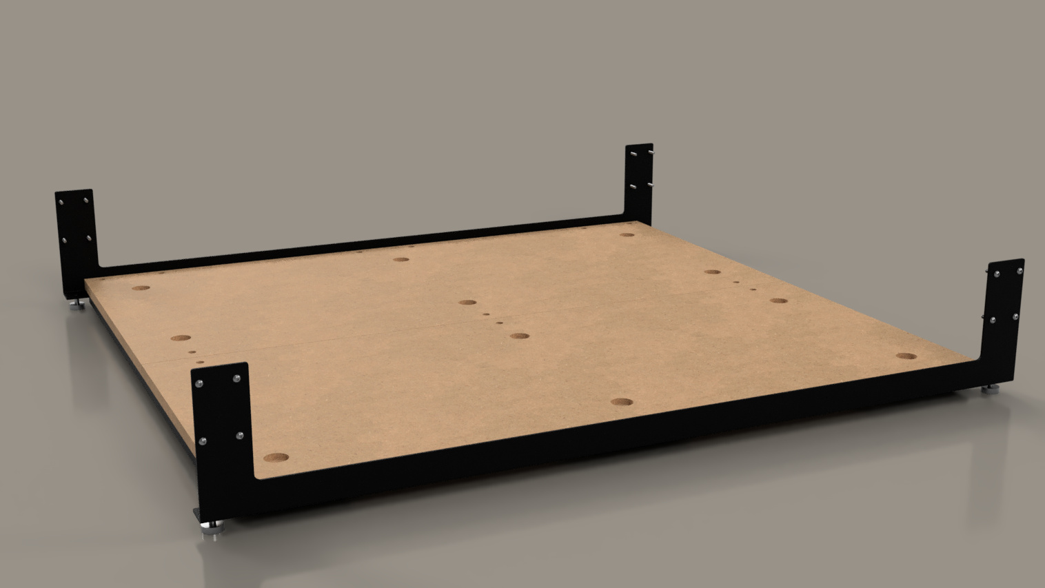
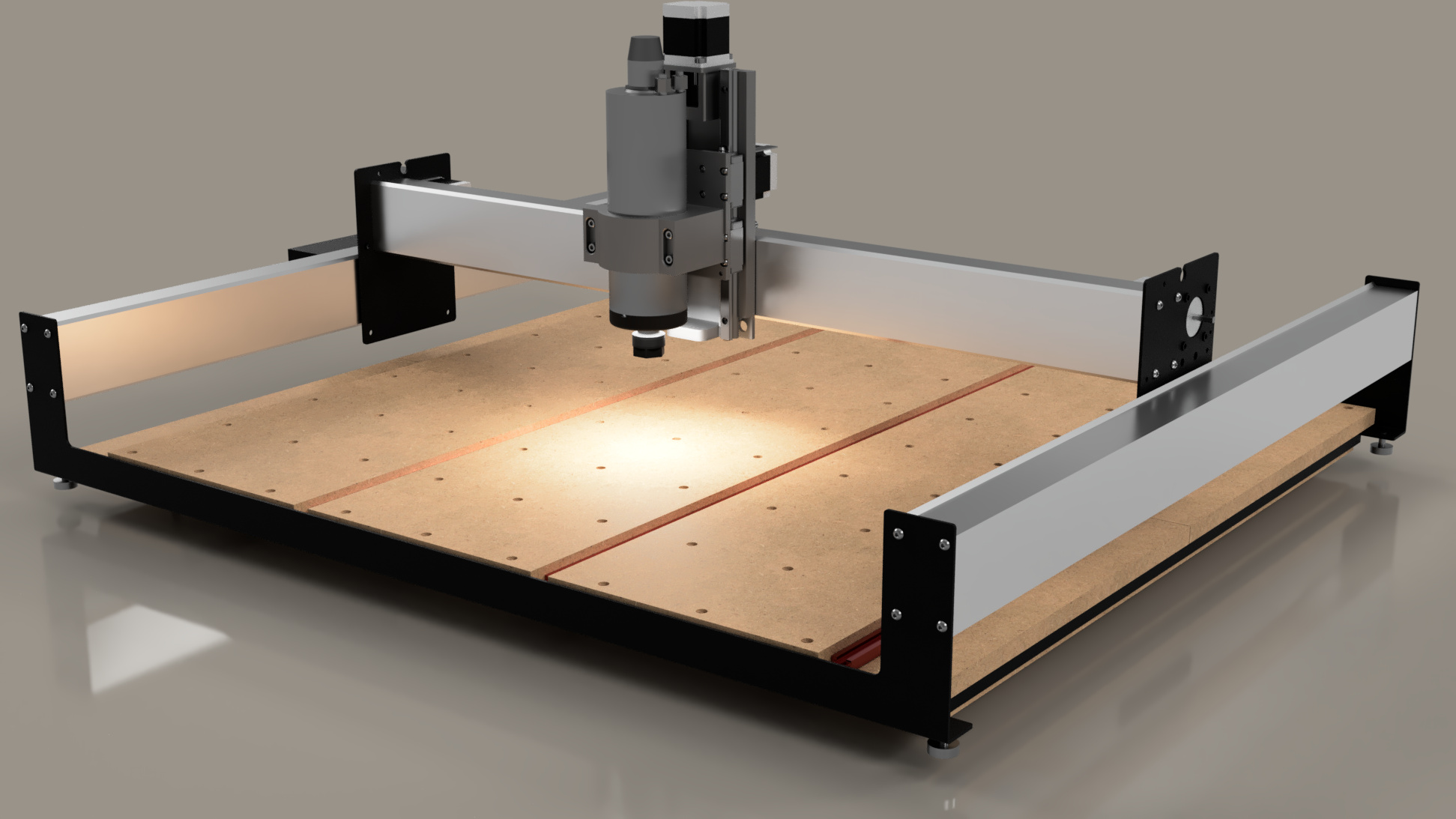
Starting with the frame, who main purpose is to hold the Y rails square to each other and level above the baseboard. The front and rear metal frames are linked by 3 steel cross-straps. This is then topped and held square by two 18mm MDF sheets.

The frames and steel straps are both folded to provide some rigidity, but this is limited over the width and depth of the XXL.

Calculating the expected deflection for one of the steel straps under a 5kg weight in the centre yields 2.2mm. This is consistent with what I measured on my machine before bolting the baseboard down to something solid.

The most visible issue to most users appears to be sagging of the baseboard over time which results in the spoil-board losing flatness. The underlying cause is the lack of rigidity in the baseboard support straps. If we are concerned with deflection and vibration, holding the workpiece still is a good place to start. Remember that there are vertical forces in cutting as well as horizontal and vertical movement in the workpiece can interact with the nodding mode of Z axis deflection.

SO3 vs XXL

In what is a recurring theme, the SO3 produces a calculated 0.27mm deflection for the same weight vs. the 2.2mm on the XXL. Score one for the Shapoko Pro.
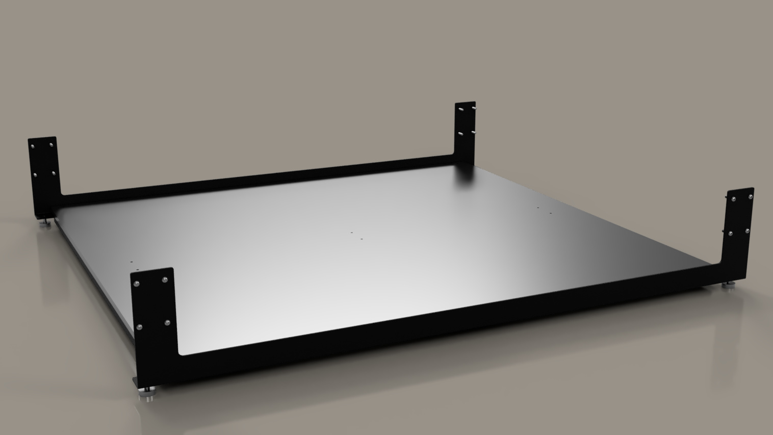
Aluminium Baseboard

As replacing the MDF with a 10mm Aluminium sheet is a popular upgrade, a quick online calculation suggests that for the same 50N load in the centre, even without the steel straps this would only deflect 0.2mm on the XXL and 0.02mm on the SO3.

Second - V Wheels

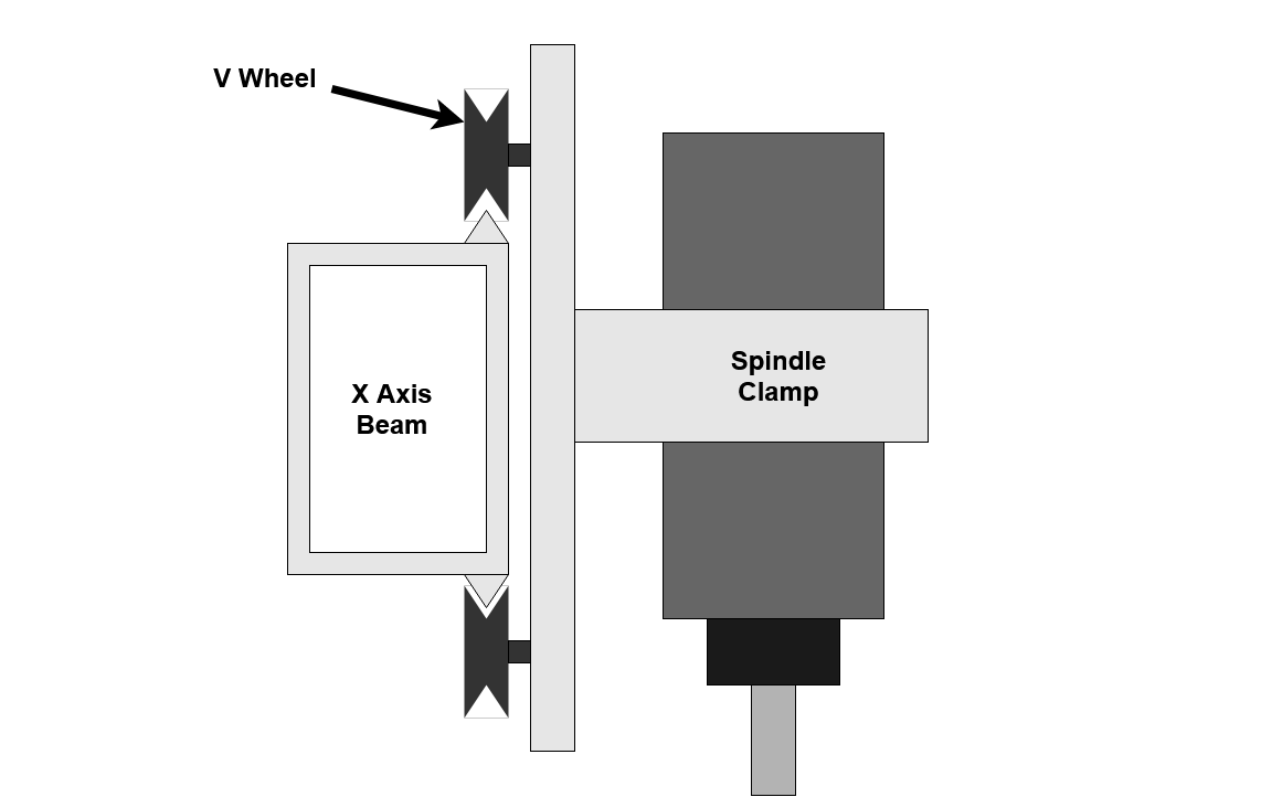
The next significant source of deflection in the machine is the V wheels which allow the linear motion along the X and Y axes. In an ideal world these would be frictionless and only allow movement in one direction, but we don’t live in an ideal world. However good our drive belts are, they can’t make up for the additional movement allowed by the V Wheels or ignore the rolling resistance.

Assuming you already have a Z+ or HDZ, the first set of V Wheels are those mounting the Z carriage to the X axis rail. These are under the greatest stress and are responsible for much of the linear motion deflection.

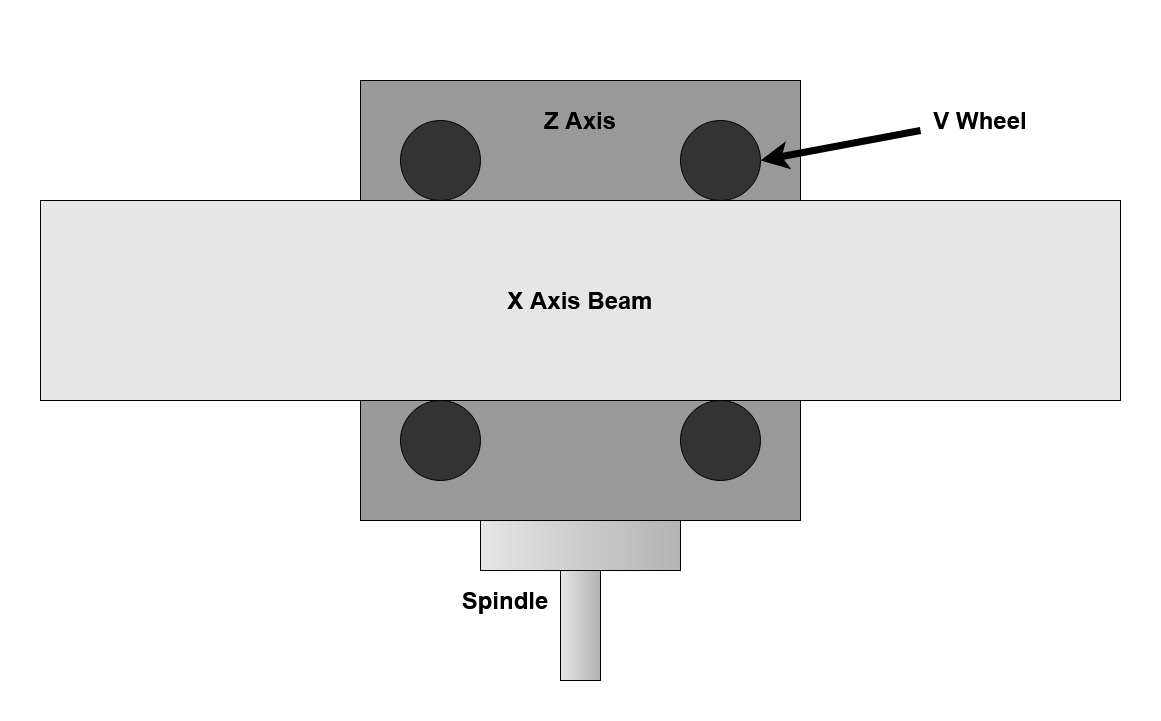
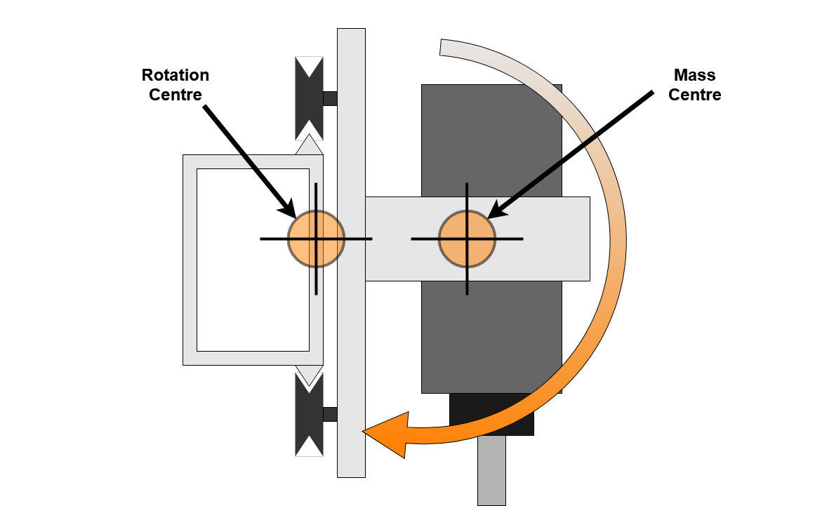
I found two main modes of deflection in the X axis V Wheels, the first is rotation of the Z carriage about the Y axis. This is allowed by radial play in the V Wheels.


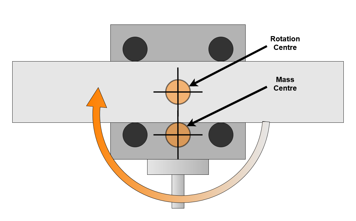
When vibrating, this rocking motion only needs to rotate the Z assembly, with the centre of rotation close to the centre of mass which further reduces the ability of the V Wheels to resist. This vibration mode is likely excited by deep cuts traversing along the X axis. The resonance for this mode is rotational and likely higher frequency than the linear belt resonance mode. Consider shaking a can of beans by twisting vs. up and down, although neither case is desirable for the bean.

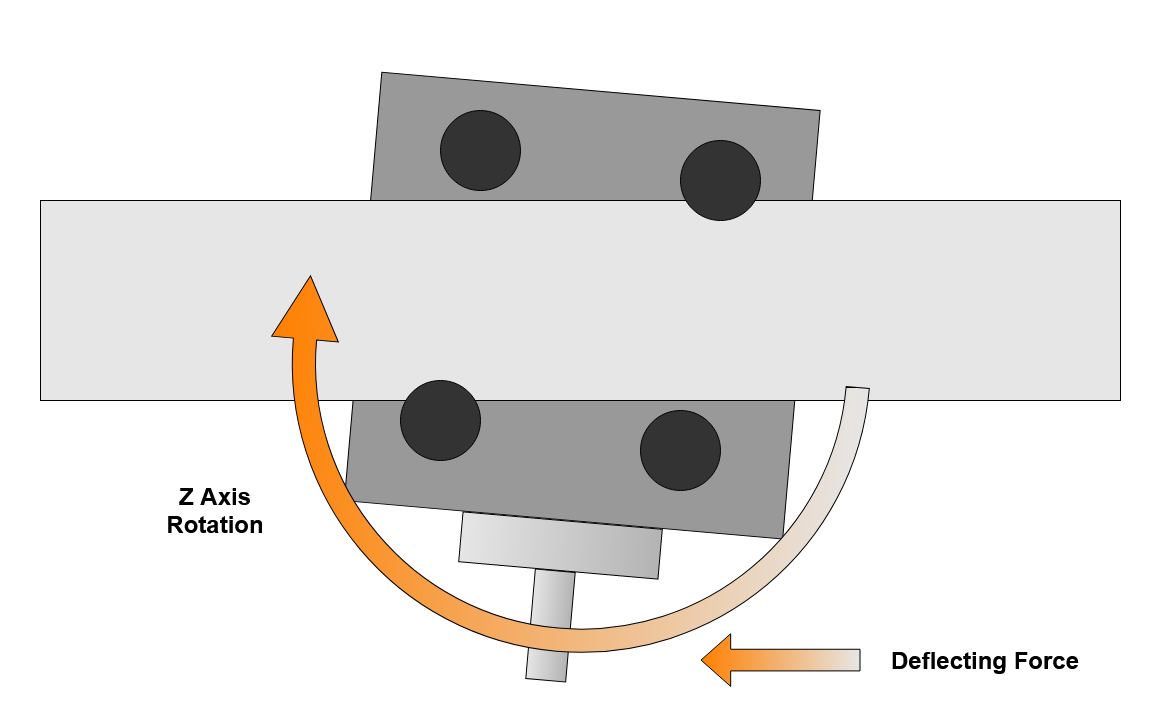
The second is a nodding movement where the Z axis rotates around the X beam, this is allowed by axial play in the V Wheels where they are less effective than in radial. This nodding movement is more displacement than rotation and therefore the spindle and Z mass take more force to move.

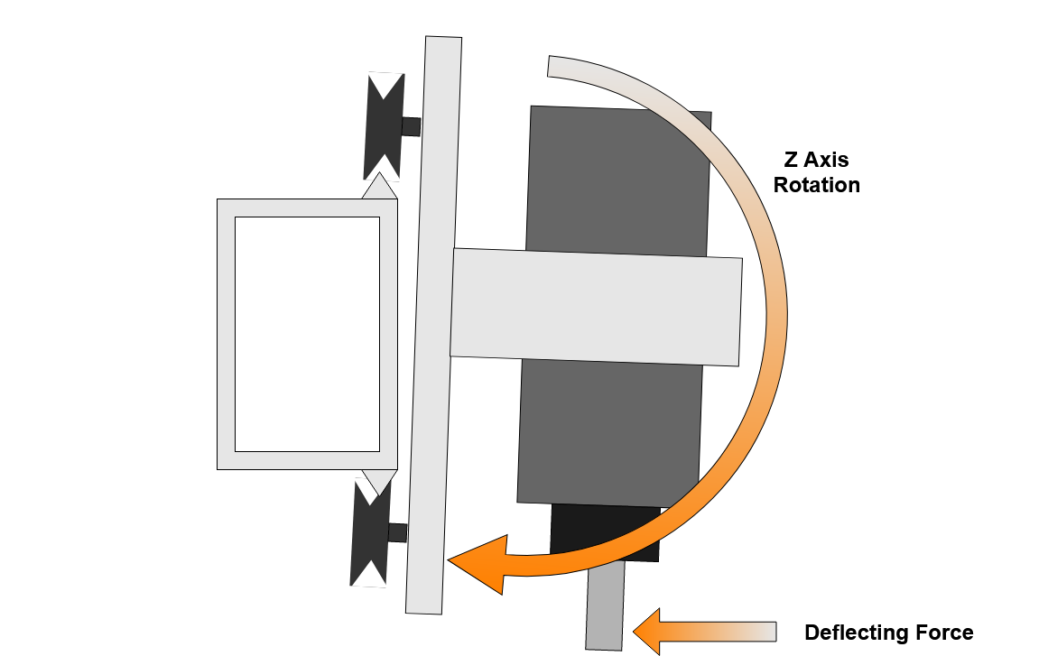
This mode is excited by deep cuts moving in X or Y axes and vertical forces generated by the helix on cutters. As this mode changes cutter vertical engagement as well as radial it can be quite violent in terms of cutting force changes and resulting vibration.

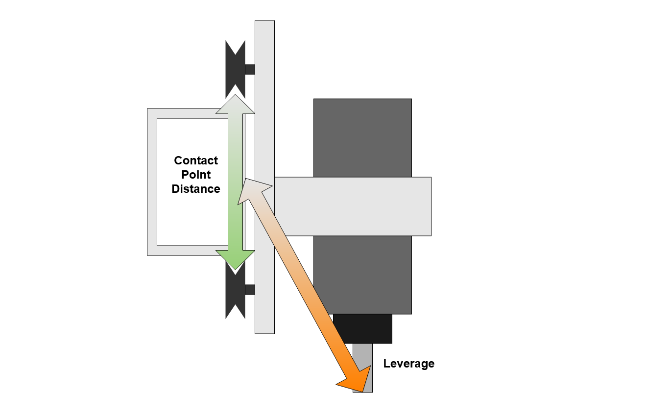
For both of these modes the small spacing of the Z carriage V wheels means that cutting forces are amplified and have high leverage over these wheels. This also suggests that stacking the workpiece up toward the X axis on additional spoilboards, vices or jigs may help reduce some vibration modes.


A common response to this unwanted movement, certainly mine initially, was to increase the preload on the V Wheels. This initially ensures that there is no gap and then starts to deform the V Wheel onto the rail making the assembly feel more rigid and increasing the effective spring force of the wheels. One outcome of this is to reduce the deflection for applied cutting forces but this only works up to a point and comes at the cost of increased rolling resistance and eventually lumpy or broken V Wheels.

Y Plates

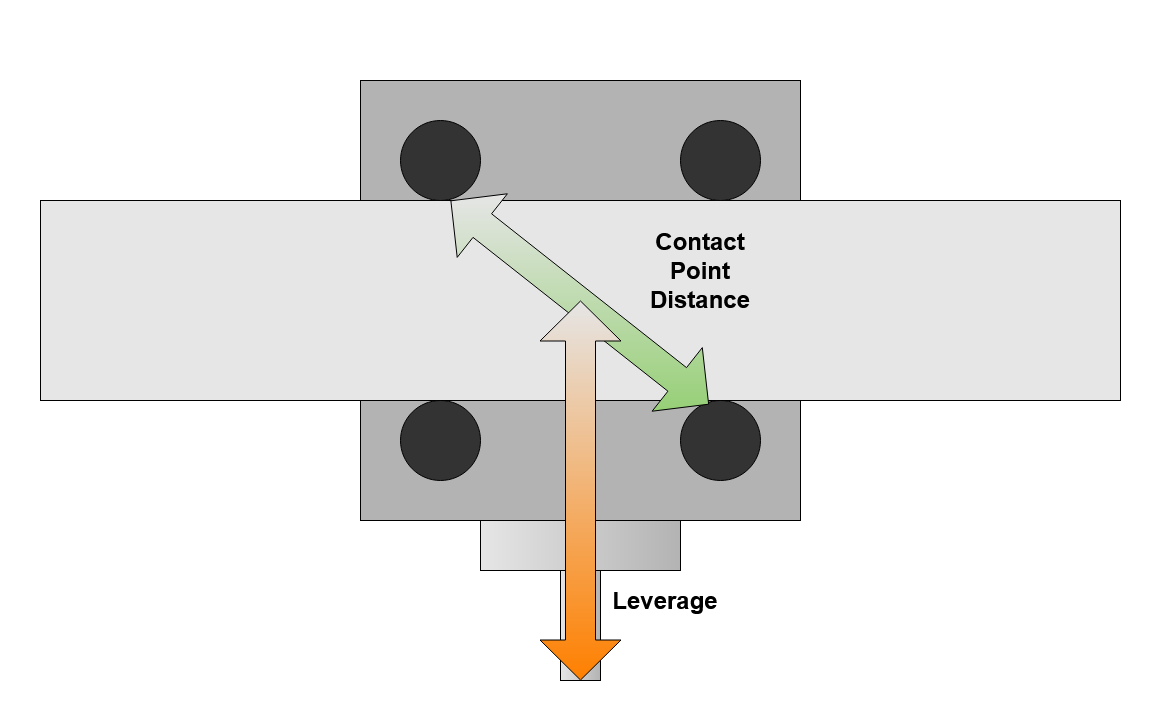
The second sets of V Wheels are on the Y plates at each end of the X beam. These show much less deflection, 0.02mm for 50 Newtons left / right in X. I think that these wheels contribute less to the overall deflection and vibration for a few reasons;

  • There are eight of them not four
  • They are spaced further apart and therefore there is less leverage over them
  • The additional mass of the X axis beam and steel Y plates

How much deflection?

On my machine at a reasonably high preload

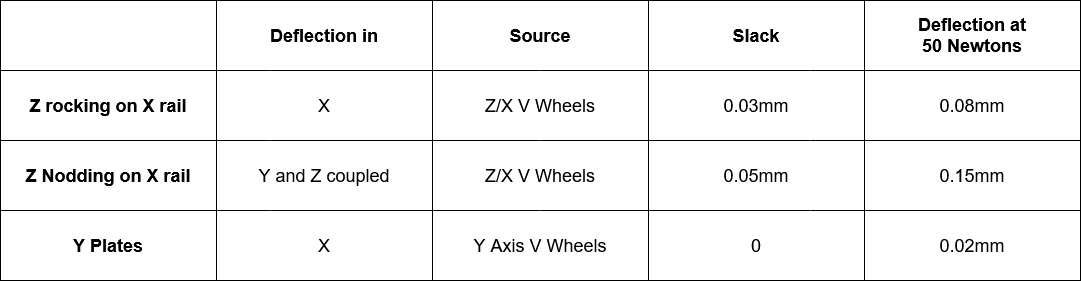
Overall, the V Wheels contribute a major part of the total deflection, even more so on the smaller machines. Increasing preload can reduce deflection a little, but at the expense of early wear-out and increased backlash. I have no recommendation on ‘how tight’ or any sensible way to measure preload.

Third - Drive Belts

The Shapeoko drive belts are responsible for a significant part of the overall deflection and, as before, more deflection on the larger machines. In particular, the belt on the X axis is likely to play a significant part in spindle vibration by allowing the Z carriage to move left and right as it stretches. This is in addition to the rotation movement from the V Wheels.

It is useful, therefore, to understand how the drive belts work. To do this, we can produce a simplified model of the belts as used on our machines.

Belt Backlash?

The first element is to find out whether the drive belts exhibit the same, bowling ball in a box, type backlash as a ballscrew, leadscrew or rack and pinion system

Gates graph
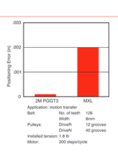
(source; Gates belt drive design manual)

Well, they do, but only a tiny amount. According to the Gates’ data (our belts are the 2M PGGT3 type) around 1 or 2 tenths of a thou (or 0.005mm in sensible units). This is impressive, but then this belt geometry was designed for positioning applications and therefore does absolute position pretty well (assuming you did all your set-screws up properly).

Belt Tension and Extension

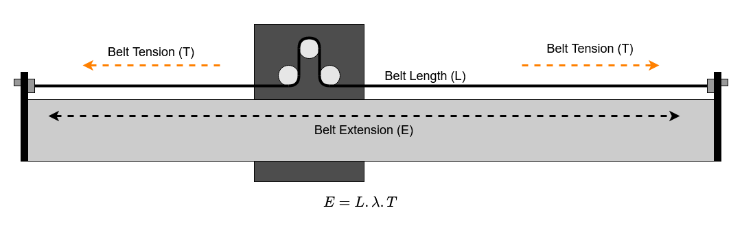
The drive belt system on the Shapeoko relies on belt static tension to work. The belts are tensioned between anchors at each end of the main axis rails. The belt starts with a nominal length and is then stretched to achieve a static tension on the machine. This works because the belt stretches elastically, for each increase in applied force there is a proportional increase in belt length. Note that this is a proportional increase in belt length so a belt twice as long will show half the tension for the same extension. This property of the belt is called the tension modulus and we have a series of measurements of this value for different types of belt. (see the measuring belt tension thread and the measurements by @The_real_janderson ).

To drive the axis, the belts pass round a set of idler bearings and over a toothed pulley on the drive motor. As the stepper and toothed pulley prevent the belt moving relative to the driven axis, we effectively have two sections of belt. Each is anchored to one side of the moving axis, with the same static tension as the axis is free to move along the rail.

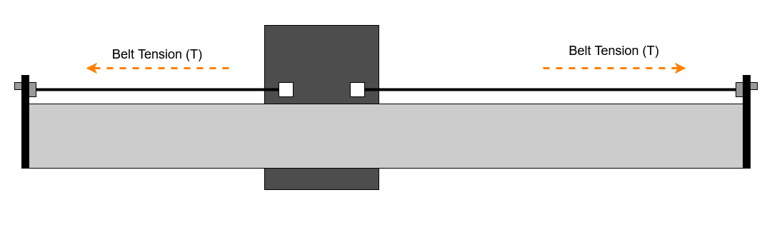
This is the resting state of the belts, equal tension either side of the moving axis, and to satisfy Sir Isaac Newton, no net force on the moving axis, the system in an equilibrium condition.

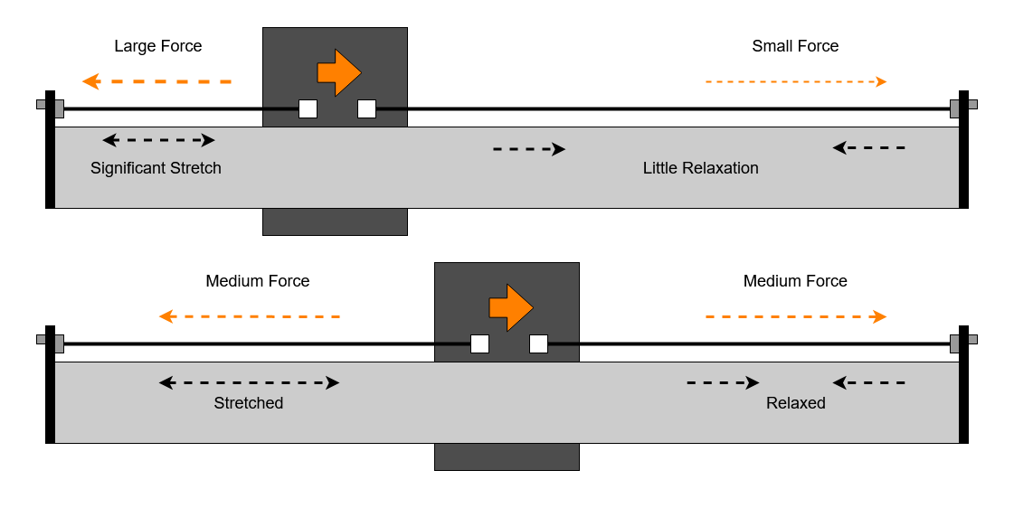
When we apply an additional force, either by driving the stepper motor to move the axis, or a cutting force from the spindle, the system needs to find a new equilibrium state where all the forces cancel out again. When this happens the belt on one side gets shorter whilst the belt on the other side gets longer.

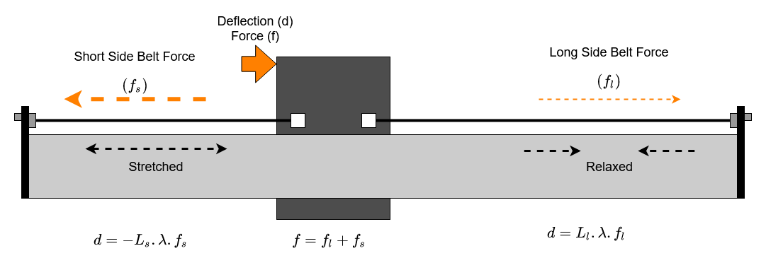
This results in a net force from the belts which either overcomes friction to move the axis or resists a cutting force. The larger the deflection the greater the force.
One complication is that, as we know, the stretch of the belt for any given tension is proportional to the length. So for any deflection the longer side of the belt is going to show a smaller change in force and the shorter side a larger change in force. This means that as we get close to either end of the axis the short side belt will produce sufficient restoring force for less deflection distance.

We can easily rearrange to get an equation for deflection in terms of force and belt lengths;

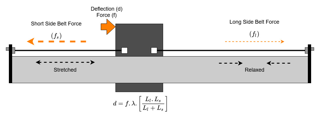
How does the belt drive behave then?

We can use the equations from those diagrams to see what impact all this has on the deflection.

These charts are based on the 9mm Kevlar belts on my machine and the observed tension modulus on the machine. I am seeing ~0.018 % extension per 10 Newtons force. This is lower than that previously measured by the_real_janderson for the Kevlar 9mm belts. This difference may be due to batch variability or rolling friction on the axis reducing the apparent belt tension.


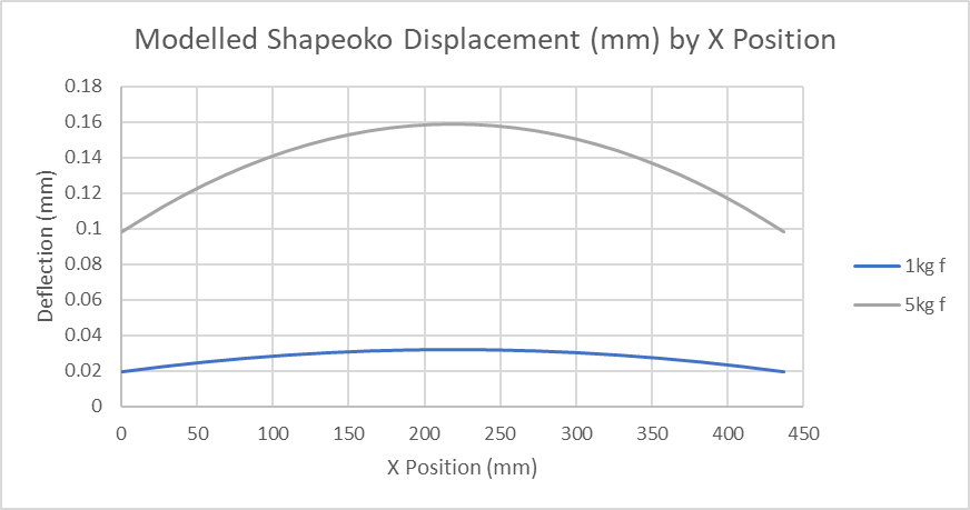
There are a few things we can see from these simplified models;

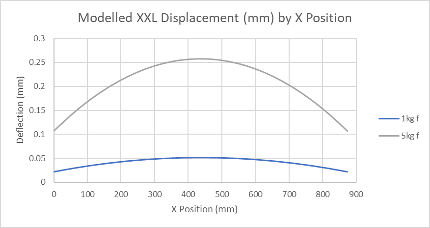
  • The belt deflections are largest in the middle of the axis travel.
  • The long axes of the XL and XXL have more belt deflection in their longer belts
  • The belt deflection seems to be linear with the applied force on the belts

The type of belt in use also has a substantial impact. We have tested or vendor data for a range of belts. Based on that data, this is the belt extension at XXL length and 10 Newtons force

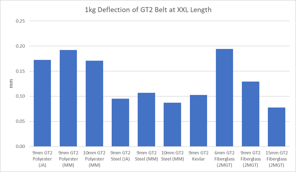
Note the 15mm Fiberglass GT2 which is the type of belt apparently installed on the Shapeoko Pro. This has only slightly better deflection performance than the 9mm GT2 Steel belts, however it does not have the early failure problem when flexed around small radius drive pulleys. The 9mm Aramid / Kevlar belts still appear to be a good option for the non Pro machines.

Axis friction

The other important element in the belt and backlash behaviour, is the axis movement friction.

On my machine it takes between 0.5kg and 1.5kg pull to move the X axis, around double this to move the Y, predictably enough as there are twice as many V Wheels, belts etc. Note that if you measure this, you need to release the belt anchors as there is significant additional movement resistance from the belt and motor system.

When our machine moves it must overcome both the cutting forces and the friction of the moving axis. This results in a certain amount of “wind up” or pretension in the belt to overcome this friction which is what manifests as backlash in the machine.

Testing my Z carriage I was able to measure the following behaviour as I increased tension on the V Wheels. This produced a range of rolling resistance and therefore varying backlash

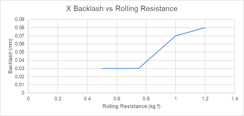
The rolling friction causing backlash is as good a reason as any to not over-tighten your V Wheels.

Slow elastic recovery

One possible source of backlash is if the belts do not immediately elastically recover when the tension force is reduced. This effect is difficult to measure. I performed a simple test to look for this by running the axis into a hard stop and then making the machine take some additional steps to increase belt tension and extension. This was within the belt stretch available from the stepper holding torque. Then I stepped the machine back away from the hard limit to observe whether it took any time to recover to it’s previous step position.

I was unable to observe any evidence of slow recovery within these belts, but this experiment was not particularly well designed.

Size of the error

Taking our measured friction of 10 Newtons we would require, somewhere between 0.02 and 0.2mm of belt deflection to overcome this force, depending upon the axis size, type of belt and how enthusiastically the V wheels are tensioned.

Not just a simple rolling resistance value

I expected this to be a relatively simple rolling resistance from the V Wheels which would give a constant force required to move the axis any distance at any speed. This was not what I observed, and I do not have an effective explanation or model for the behaviour I found.

Testing backlash by reversing direction and moving down from 1mm through 0.25mm to 0.025mm step sizes. At the 1mm step size we see 0.03mm to 0.04mm backlash on this machine, so we would expect to lose an entire step at 0.025mm .

That’s not what happens though, what we seem to have instead is a force required to move the wheels and bearings which depends upon the distance they are being moved. This is presumably some element of plastic deformation as the wheels roll.

The chart shows deflection on the X axis for four different V Wheel tensions. aside from increasing backlash around the zero there is no other significant variation at this measurement accuracy.

Inconsistent Rolling Resistance

One interesting experiment is to disconnect the drive belts and use a weight and pulley to pull the Z carriage along the X axis of the machine. We might expect this fixed force, with just enough weight to overcome the rolling resistance, to smoothly move the Z carriage across the machine.

This is not, however, what happens. As they roll, the V Wheels show significant variation in observed rolling resistance. This varying resistance is likely to affect both precision of movement and backlash by requiring different belt extensions to move at different points on the axis.

(this bit was better explained by the video)

Measurement Time

So, we have some ideas about what is going on but now it’s time to get some real data from the machine. We have a model of the belt behaviour, but for that to be useful it must make testable predictions about the machine.

X Axis Slop, Deflection and Backlash

First I measured the X axis slop, deflection and backlash due to the belt system, at 12 different positions across the X axis. To isolate the belt deflection and minimise the contribution of other sources such as the V Wheels, these measurements were made between the X rail and the side of the HDZ close to the X belt. Force was applied to a rod clamped in the collet where the machine would normally see cutting forces. V Wheel tension was set to give just over 10 Newtons of rolling resistance.

To provide a repeatable force, a cord was attached to the rod, and hung over a pulley suspending a 5kg weight. At each location the slack was measured by moving the rod left or right by hand, and observing the distance between where it came to rest when the force was removed in each direction.

Before the deflection measurement, the spindle was moved to the slack position in the same direction as the load to be applied. I did this as I thought it would be less error prone than attempting to set the machine to some notional ‘zero’ position within the slack region. The additional deflection under the 5kg weight was then measured.

Backlash was measured by stepping either left or right in 1mm step mode, reversing direction and observing how much less than 1mm the first direction reversing step recorded. The steps/mm was set to 40.000 on the controller for this test to avoid measurement complication.

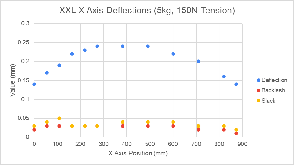
The first thing to note is that there is quite a bit of variation in this data, the noise floor appears to be about 0.03mm.

Comparing with the Belt Model

Comparing our measured data with the predicted behaviour from the belt model we have a chart showing;

  • The measured slack against the expected belt deflection for 1kg rolling friction
  • The measured deflection at 5kg against the expected belt deflection for 50Newton force

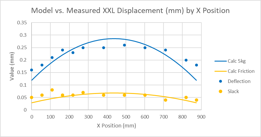
The correlation is pretty good given the limits of the test precision and suggests that our model is useful in capturing the basic aspects of backlash and force deflection behaviour in the belts.

Y Axes’ Drive Belts

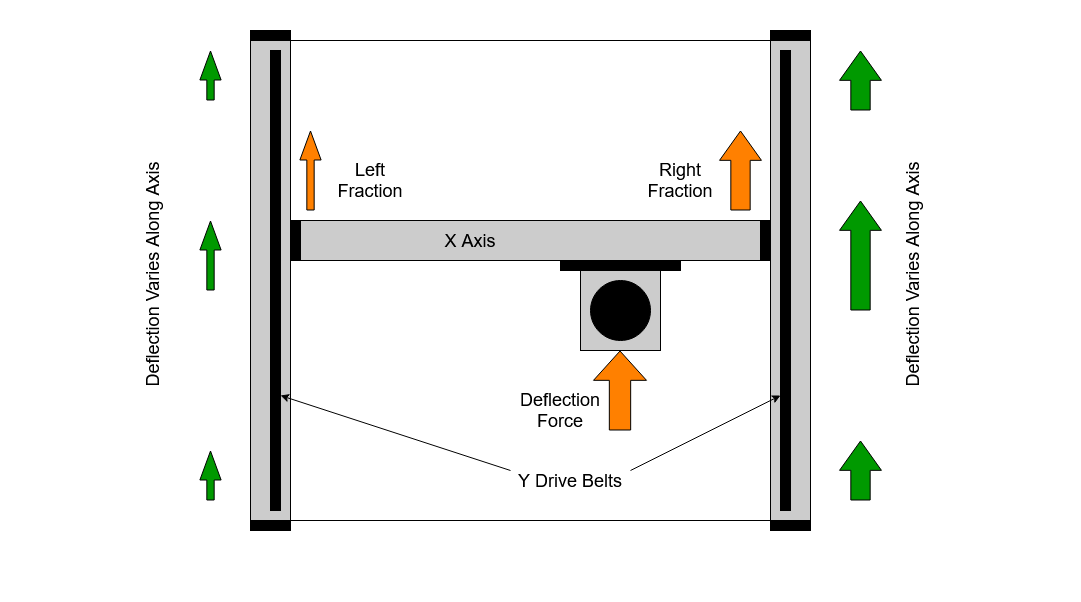
The Y axes are a little more complicated as we have two of them acting together, one at each end of the X axis. This means that the forward / backward forces are split between the two Y axis belts, but in a variable proportion depending upon the X position of the Z carriage.

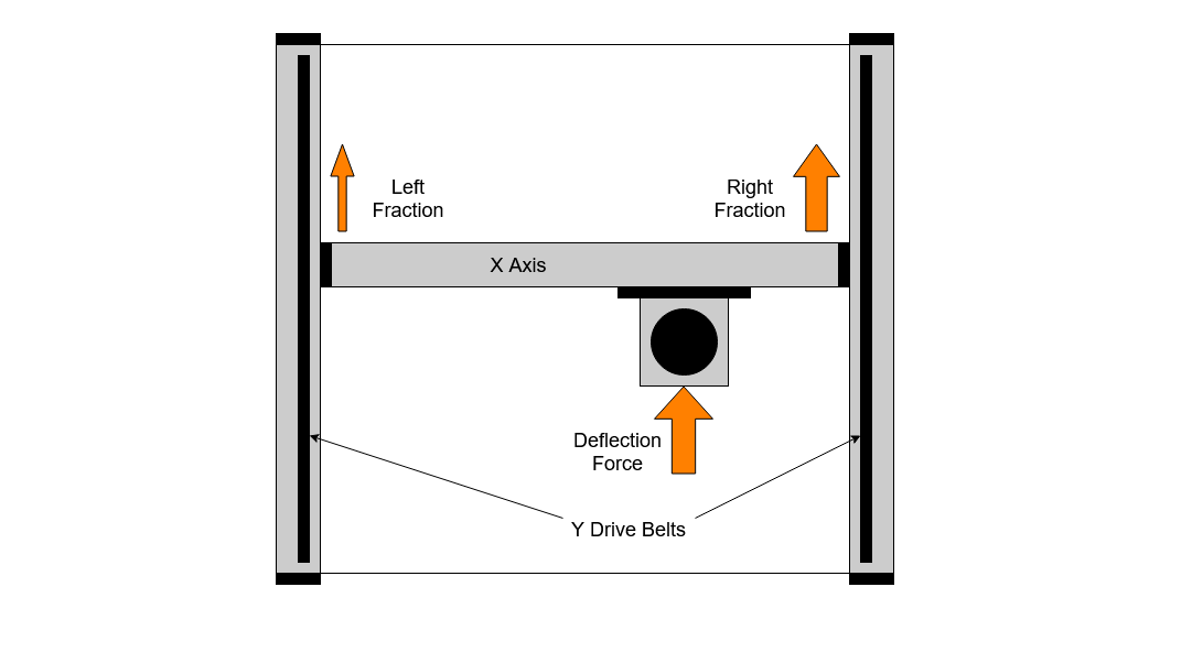
We can use the same belt deflection model as before, but this time we need to split the force across the two Y axes. We will do this in simple linear proportion as we move left to right on X. We can now calculate the expected deflection for both Y plates for any position of the Z carriage on X

This makes quite clear the variation in forces on the two Y belts and stepper motors as the X position changes. In the middle, we have approximately double belt and motor strength but at each end we drop back down to single.

Using this, we can now calculate the combined effect on the Z carriage position

Axis and Steel Plate Deflections

Initial comparison of this model to the measured data showed larger differences than I was expecting or happy to accept, which meant I had to think again about what else might be happening and then take some further measurements. I found that on the XL and XXL the X beam deflection is not negligible, also that the front and rear steel plates were deflecting a measurable amount.

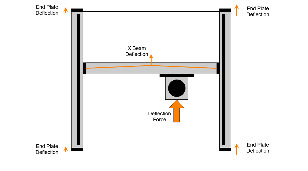
We can calculate the expected deflection of the X beam extrusion using some common engineering maths. We know the Young’s modulus of Aluminium is approximately 70GPa and we can calculate the bending resistance of the beam. We do this using the second moment of inertia, which is based on the cross sectional shape of the beam. Using these numbers and applying a 50N force in the centre of the X beam we get an expected deflection of 0.027mm which is consistent with the ~ 0.05mm peak to peak I measured on my machine.

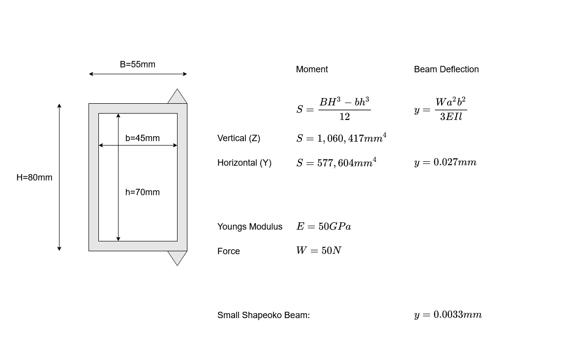
Notably, if we calculate this for the short X beam of the standard Shapeoko the expected deflection is 0.0033mm, almost ten times smaller.

The deflection of the steel vertical endplates at the front of the machine was also measured and found to be 0.05mm for 50 Newtons, double the peak X beam flex . As we found for the Y belts, this varies with X position as the force distribution alters between left and right.

Model vs. Reality

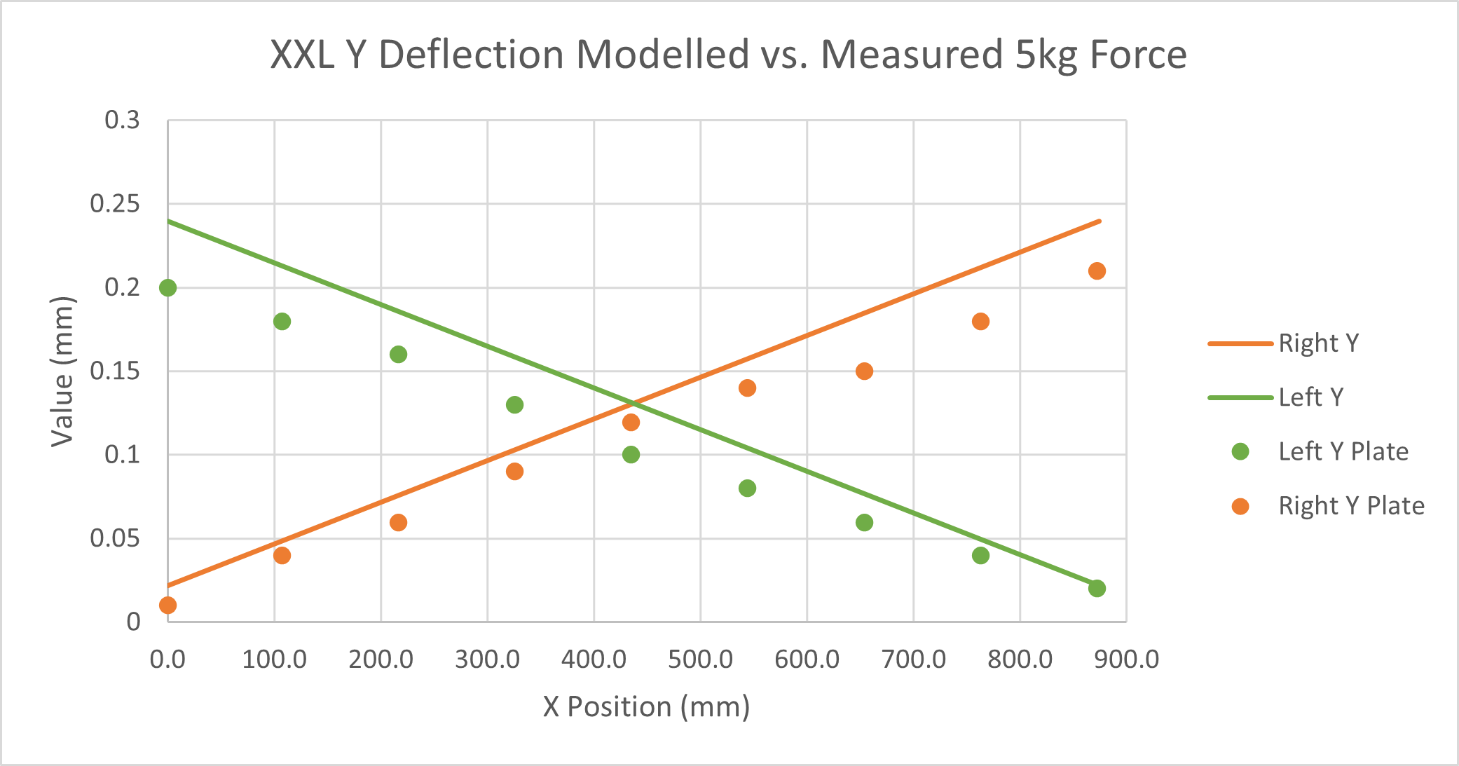
Incorporating the beam and plate deflections and then comparing the new model with the measured data, we have a reasonable alignment of the left and right deflections, with an error increasing as we approach the ends of the X beam

Comparing the Z carriage behaviour we have a pretty good alignment of the modelled and measured data

The slack is, as expected, very close to that on the X axis;

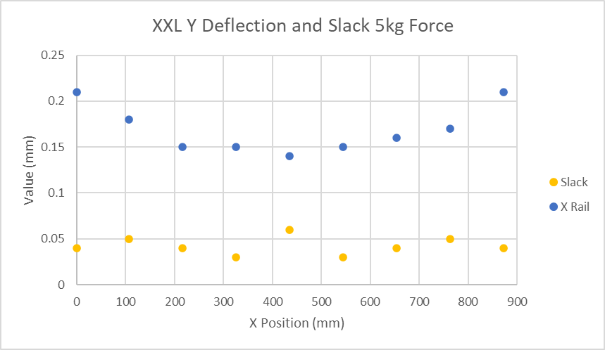
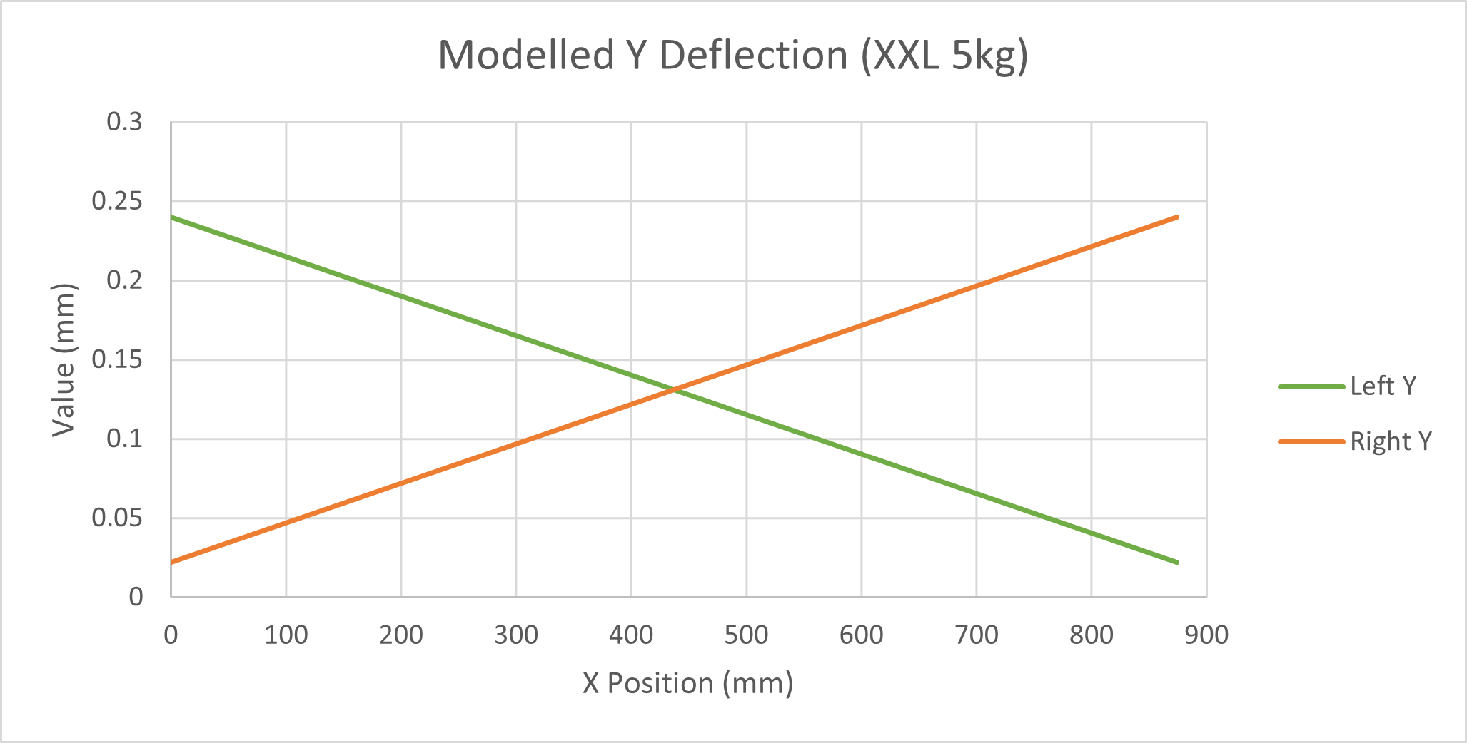
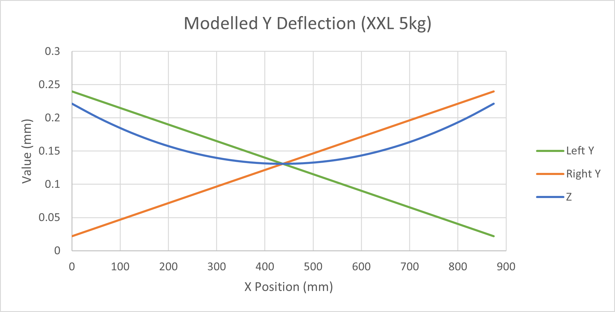
Y Deflection by Position

The Y deflection, as we’ve seen is a bit more complicated than on X. We’ve seen how it varies with X position but, as we already know, the belt deflection will also change as we move along the Y axes. To understand this properly we need to model what happens as the machine travels front to rear as well as left to right. We can use basically the same model we did for the X belt, just applying the appropriate share of force.

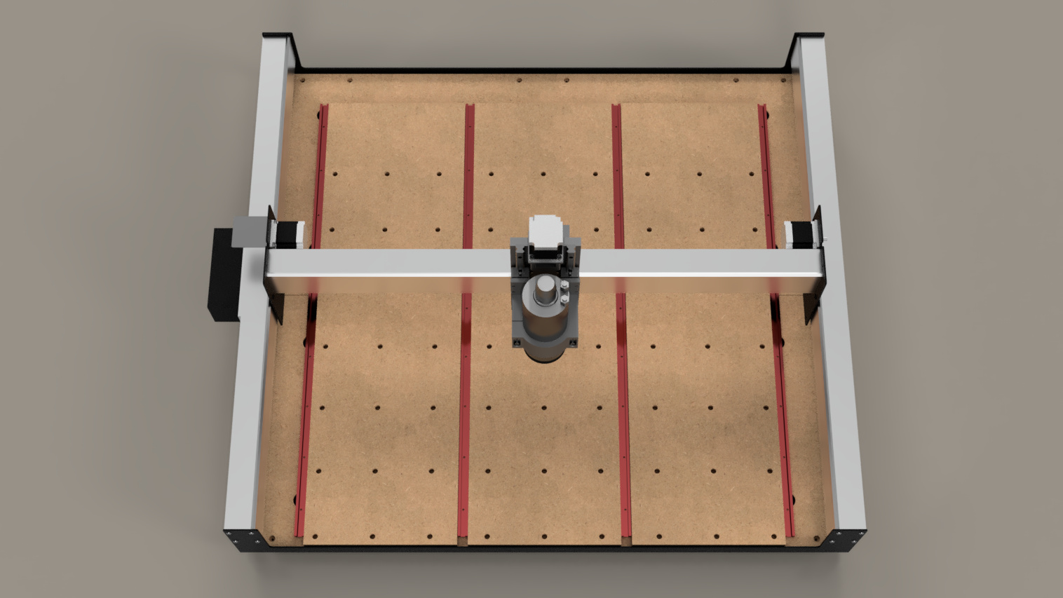
Viewing the machine from this direction

We can plot the expected deflection of the Z carriage, in the Y direction like this. The graph is showing the Y deflection in the vertical axis and as colour bands. The surface shows, as the spindle moves around the machine in X and Y and for the same force, how the Y deflection varies.

We can see that the deflections are lowest at the front and back of the machine and worst at the left and right ends of X midway between front and back.

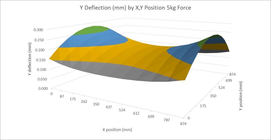
This model is within ± 0.03mm of the measured deflections on my machine so I believe it is a reasonable, if simplified, representation of the major effects.

Overall Deflection

Bringing everything together…

We have measured, developed a model, re-measured and made a better model and captured, what I think, are the major elements of deflection. We’ve also seen how various components of the deflection vary as we move in the X and Y axes. It might be interesting to see how this all adds together into the overall deflection of the machine.

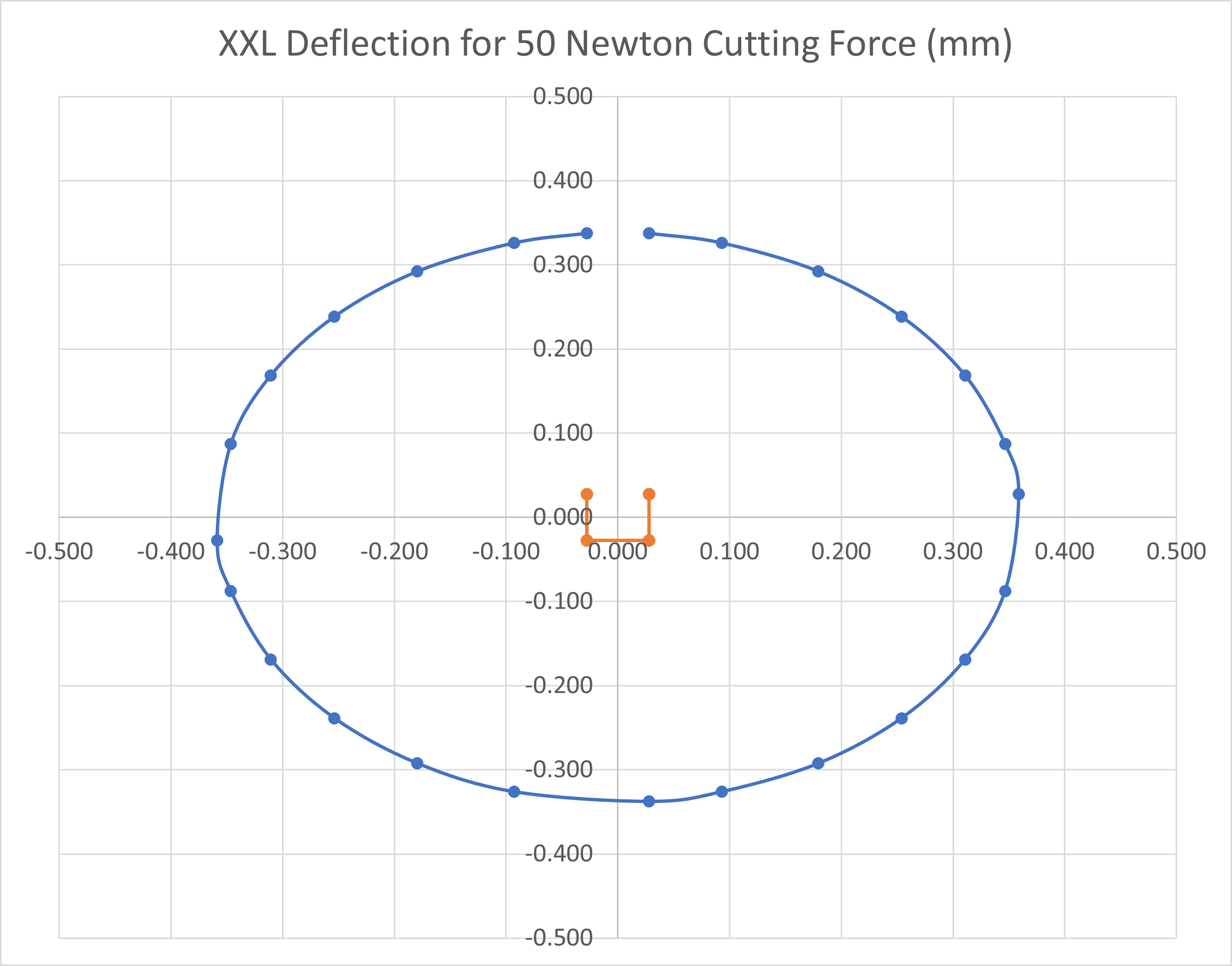
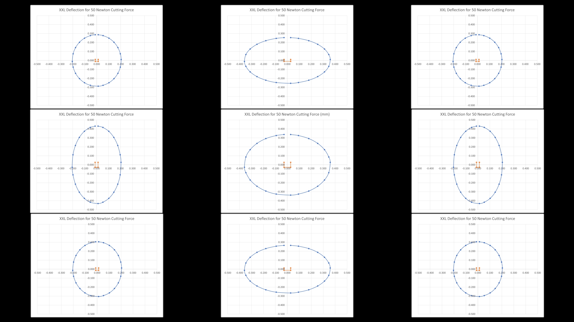
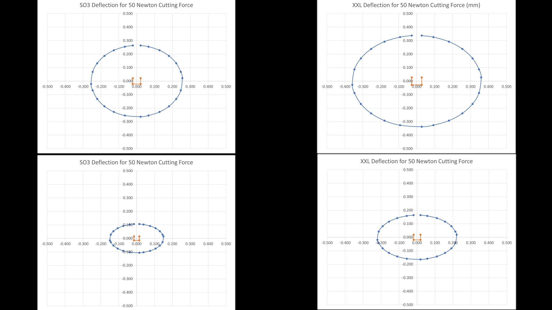
To do this, I’ve used the combined model to plot the resulting deflection for various directions of force on the cutter. The plots show the expected deflection for a 50 Newton cutting force with it’s direction rotated around in 30 degree steps. I apologise for the slightly ugly graphs, but I made them in Excel so that it was easy to share. I’ll post the spreadsheet for anyone who wants to use it.

Remember that we are only plotting deflection in the X, Y plane of the baseboard and not including vertical components such as those seen in the spindle nodding motion.

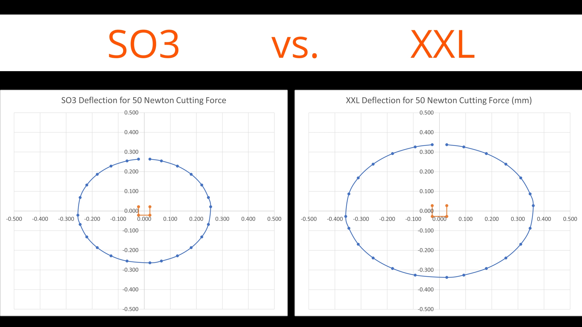
First we have the plot for the central position on the XXL, the orange box in the middle is the slack and then we see the slightly oval deflection for 50N force in blue, there is a bit more deflection in X than Y in this position.

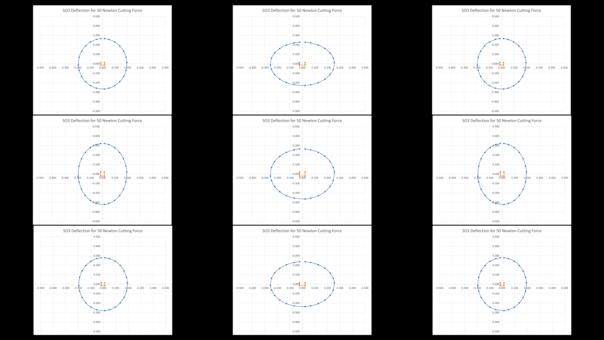
Now for the other positions, the plots are laid out as per the Carbide Motion compass points looking down on top of the machine

On the XXL we can see that the blue deflection plot becomes a lot more oval at the N and S positions as Y deflection reduces as we get close to the ends of those axes. Similarly the W and E become more oval, but this time due to reduced X deflection but increased Y deflection. The four corners are about the same as each other with similar Y deflection to the centre position but reduced X deflection.

Comparing the SO3 with XXL we can see that the standard machine, despite having the same V Wheels, outperforms the XXL by a significant margin thanks to reduced belt stretch and beam flex. Remember this is not including baseboard bounce. It’s becoming quite easy to see why cuts that are achievable on the standard size machine are more of a challenge on the XL and XXL.

Looking at the rest of the positions for the SO3, we have a similar pattern but with a smaller central deflection oval as well as smaller, better controlled, N, S, W and E plots. Interestingly the four corners are very similar to the XXL despite that machine’s higher deflections toward the middle of the axes.

Upgrades

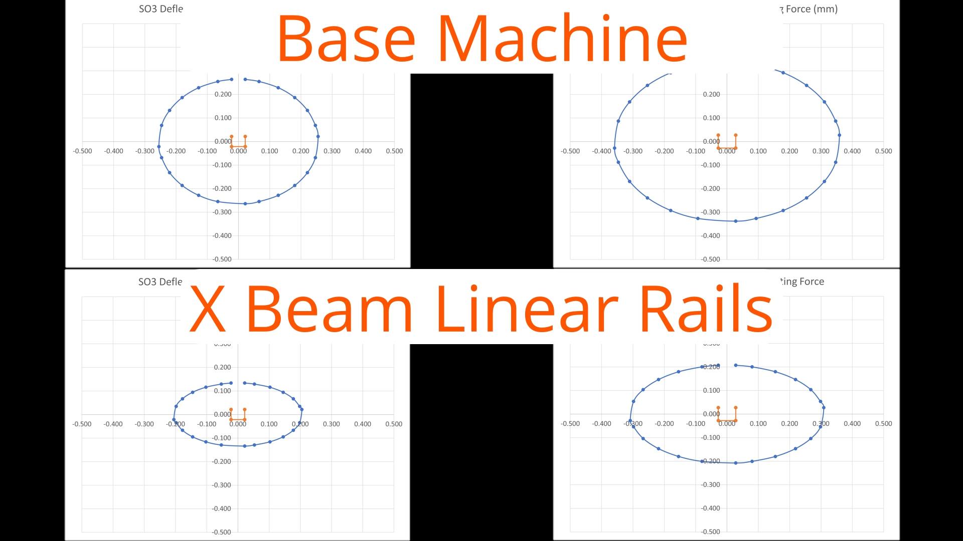
We can also take a look at what we might achieve with some upgrades, that some of us may already be machining the parts for.

Here’s what the model says about replacing the V Wheels with linear rails on just the X axis. The measured deflections from the Y axis V wheels are much smaller. The change in behaviour is quite significant in both machines, mostly in Y but likely to have quite a strong effect on vibration too as the V Wheel deflections are close to the spindle.

And if we took the next step and upgraded to 15mm wide belts, but with Kevlar or steel core rather than fibreglass we could reduce the belt deflections as well and get something like this

Next Steps

That’s what I’ve got so far, what are the next steps?

  • More measurements, clearly :wink:
  • Proper FEA modelling of the machine to look for the major vibration modes and determine where additional stiffness & damping can help.
  • Measure how much of the observed belt deflection is actually coming from stepper motor angular deflection and update the model with this data.
  • Properly measure a standard sized SO3 to compare with the XXL and get frame deflections etc.
  • Measure an XXL with X beam linear rail upgrade (I will do that soon)
  • Measure other belt options installed on the machine
25 Likes

Fascinating, thorough and hugely informative - a reliable information toolkit to systematically achieve better performance…

4 Likes

I started going through this right after you posted it and finally just finished. Incredible work @LiamN. This is a fantastic resource for understanding these machines. Well done.

4 Likes

Thanks guys, glad to hear it’s useful to people, I’ve learned lots from the folks on here and really appreciate the tutorials and ideas people share.

I initially planned a bit of measuring to see whether deflection or backlash were reduced by more belt tension but then I redefined the meaning of scope creep as each time I measured I went further down the hole.

If anyone wants any of the drawings or other source material let me know.

8 Likes

Excellent work Liam.
Yes, this thread is a definitive bookmark, just like the belt tension dissertation.

3 Likes

Obviously I added this to the community map.

What resonated most (pun intended) with me :

  • the XXL is a different beast than my SO3 and I tend to forget that when discussing dimensional accuracy.
  • placing stock in corners of the work area is a simple way to minimize belt-related deflection
  • raising the stock as much as possible (limited by clearance under the X axis) is an easy way to reduce Z axis front/back deflection.
  • the comparison of values is fascinating, but the absolute values themselves continue to impress me (particularly the SO3 values) and match my experience of being able to produce very precise parts with the roughing+finishing approach

I can’t wait to watch episode 4 after your linear rail upgrade.

9 Likes

also makes me ponder a counter weight behind the Z axis…

1 Like

Folks have done a counterweight when running a machine on a vertical mount — it works, but doubles the mass the stepper motors have to move.

1 Like

hmm true. well it’s really about counter “torque” so mass times distance to move the center of gravity… so smaller weight but longer arm perhaps :slight_smile:

3 Likes

What about a constant force spring though instead of a counterweight? It wouldn’t add much mass.

@LiamN

Awesome white paper!!!

So, one question I have is how much deformation of the v-wheels is induced by just having the machine powered off in the home position? And how long would any deformation of the delrin wheels last (minutes, hours, days, etc.)? (Maybe it would be a good idea to un-mount the z-carriage if one knows they wouldn’t be using the machine for a few weeks…)

Would running a 'warm-up program help smooth out any v-wheel deformation before using the machine for a precision job?

Finally, is your recommendation to tension the v-wheels to ~7.5 newtons?

2 Likes

And, not particularly energy efficient, but it would be a solution for the x-axis v-wheel deformation to have an external motor with a pair of strings, one each looping through each left and right endplate and attaching to the respective left and right sides of the z-carriage, slowly pulling the carriage to the left until stop, then pulling to the right until stop, while the machine was powered down… Super slow, like 1mm per minute…

This is obviously overkill… I need to remember be happier with what I can do, I couldn’t do anything like this 10 years ago. And the law of diminishing returns always kicks in (definitely outpacing my operator abilities): It always seems to be the case that to attain the final 3% of accuracy will cost me more than I have spent so far…

1 Like

:wink:

Yep, I wonder if @Vince.Fab will do separate proven cut recipes for the SO3 and XXL?

Yes, the accuracy was better than I expected it to be. I thought initially that I was chasing a backlash of about 0.1mm as that was the additional clearance I was having to add to the CAM but this appears to have been a combination of my over-tensioning the V Wheels (one on my HDZ was tight even at full adjustment) and cutters that were under-sized either through being blunt or just cheap.

1 Like

Thanks, I’m glad people are finding it useful.

Whatever the plastic Carbide uses for the V Wheels seems to be pretty robust, my machine has sat for several weeks at a time and the lumpiness goes away in a few minutes after starting the machine moving.

I deliberately filmed that pull test where it was all lumpy after it had been stationary overnight in order to capture a visible example.

Thinking about it, I’d say that keeping the rails and wheels clean and free of crud build up is probably a more useful endeavour, foreign object debris doesn’t just revert to shape.

I didn’t find any sensible way to measure the tension on the V-Wheels and bear in mind that whenever you add V-Wheel tension you’re increasing axis rolling friction, making any lumpiness worse and increasing backlash.

Measuring the resulting drag is one way but you need to remove the belt on that axis to separate the belt and motor drag which means re-tensioning so that’s lots of work and potential belt / steps recalibration.

I’m going back to the ‘just tight enough that I can’t turn the lower V Wheel with one finger’ tension on mine as I’m happy to trade a bit of cutting speed for lower backlash in my finishing cut.

Is that a useful answer?

5 Likes

I would be very interested to see a comparison of this. I suspect there’s a trade-off to be had between the weight of the carriage and spindle ‘preloading’ the Z nod down to the bottom and giving a predictable Z height (at least for the HDZ and Z+) vs the other deflections that are made worse by that static torque loading around the X beam…

Yes, that is the more useful ‘rule of finger’ for tensioning…

(Footnote: The ~7.5 newtons was intended as the force to roll the entire carriage, so for each pair of v-wheels, but I think the method you just described would be a better guideline.)

3 Likes

@Vince.Fab provided a good demonstration and explanation of that in this excellent video. Apparently these types of machines are better suited to high feed machining (HFM) than high speed machining (HSM) - but also with high cutting speeds (SFMs). @spargeltarzan, maybe high SFM and HFM endmills with material optimized rake angles and edge radii would be the “cat’s meow” for these machines?

6 Likes

Yep,

It’s all consistent which is good. I’m sure I recognise that spreadsheet he used :wink:

Also interesting to see how close to the mark Millalyzer is on the cutting performance predictions.

Be interesting to see if the same speeds are possible on an XL or XXL with it’s larger deflections. I note he was using a Z+ for that which is a good vote for that as a non-wobbly Z axis.

4 Likes