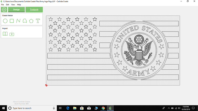
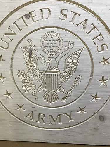
I am trying to cut army logo on a flag, 16X30 flag. I cut the logo on a test run with a 60 degree solid carbide bit, I didn’t like the amount it cut away on the eagle and everything inside the circle, not leaving great detail. The circle stars and words were fine. I ordered a 30 degree, .005 tip, and was gonna try that on just the stuff inside the circle. I entered it as a contour and as a Vcut. One showed 144 hours to cut and the other 29 hours, and on preview it shows pretty much nothing but some scattered spots.I also tried a 90 degree v bit and it took too much material. Can somebody help me with the right bit selection? this is the one thing that has baffled me since starting this cnc stuff and can’t find any info on line that has helped me yet. Thank you!
A 60 degree endmill should have worked pretty well.
The 30 degree will result in a deeper cut which may provide more detail — could you send us a photo of what the cut looked like?
Usually if a V carve doesn’t work out it’s a matter of adjusting the selection or adding an additional bit of geometry (for problems which reflect in the preview), or of getting the machine and the stock levelled/trammed (for problems where the cut has problems not shown in the preview).
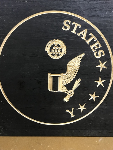
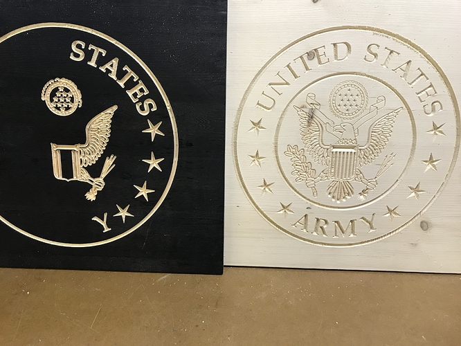
The test run is on the unpainted pine. It wasn’t too bad. Especially the small circle above eagle with little stars and design around it. But look at the partial cut on the one painted black. Look at difference in stars and detail of little circle. I stopped it because I wasn’t happy with way it was coming out.
Did you use the same gcode file for both the unpainted test run and the painted one? If so, my guess is that your zero height was set a little lower on the painted one, and it cut too deeply. It could be that the painted material is slightly thicker and you didn’t re-zero the Z height, or the Z zero height wasn’t set just right for the material. Does your V-bit have a slightly flat tip or a very pointed tip? A flat tip could cause you to cut too deeply if you don’t compensate for it.
I was wondering if that might be part of the problem. I’ve been having similar issues lately on other stuff too, but still not understanding the difference in these bits and what detail which ones do. Looks like I may need to invest in a probe I guess???
You should be able to zero this without a probe as well. How do you currently zero your z-height before milling?
I had similar issues with detail work (my text kinda bubbled up?) and changed from the slipgauge method of zeroing z (sliding a piece of paper back and forth). I now take the z down within a few mm of the work piece and loosen the collet allowing the v bit to rest (don’t dent the wood!) on the surface then retighten. Not perfect, but dramatically improved my detail.
Might be worth trying before shelling out for the probe?
Same exact gcode for both
I use the paper method to zero
This thread explains how V-bit tool paths are calculated:
This assumes a perfectly sharp tip to the cutter. If the tip of your cutter is not perfectly sharp (it won’t be) then when you zero the Z height, you will actually be a little bit lower into the material than expected, and your cut widths will be wider, causing an effect like you have seen. The same thing happens if your material has a varying thickness and you zeroed at a thinner spot. This will be the case whether you use the paper method or a probe for zeroing.
You could try compensating by moving your Z zero up slightly so that the bit won’t cut as deeply. That is essentially what @JoeyMoose is doing with his method, but you could jog up even very slightly more and then zero if necessary.
This topic was automatically closed 30 days after the last reply. New replies are no longer allowed.


