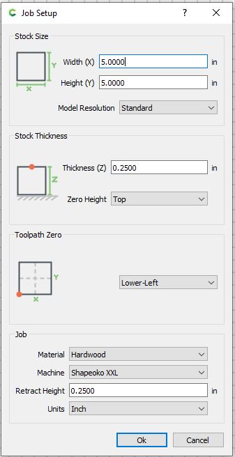
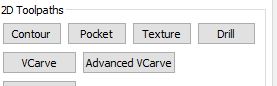
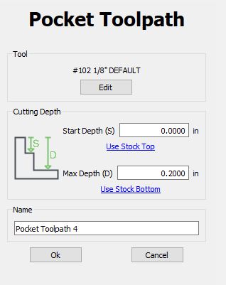
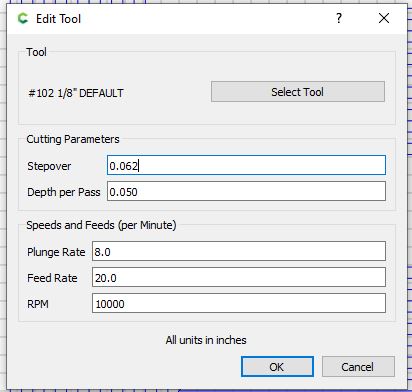
Hi Warmage, when I surface a piece of wood, I enter the dimensions of the workpiece in the design tab of CC and then make a square. Then I go to the toolpath tab, select the square and make a pocket with a .03 depth of cut and a stepover of 1in since you have a 1.5 in surfacing endmill. For the first try, I’d be even more conservative and make the DoC more shallow until you get a feel for your work environment.
I do the same thing in terms of making very shallow passes until the entire surface. Then I will do one more pass with a very small stepover so I don’t have to sand at all. Then I can flip it over and to the same to the other side or surface down to my desired thickness.
One possible workaround is what @WillAdams mentioned in this post, manually creating the raster path as an open vector, and using a contour toolpath. A bit tedious, but you then have full control, can start the toolpath away from the stock edge, etc…
You could for example decide to set the zero reference in the lower left corner, set your work area to the specific dimensions of the wood slab, and draw the line/vector starting from outside the displayed work area.
And then generate the G-code, zero off the lower left corner of the slab.
To make sure you setup everything correctly, a good practice is to run the file as an air job first: artificially set your Z zero one inch above the slab, and run the file, to make sure the router moves along X/Y as you expected.