OK, so I recently upgraded to z-plus foolishly thinking that my z issues would be resolved entirely (which I had attributed to missing steps when milling thick stock).
After finally getting a workflow set up for two-sided milling using an aux spoilboard, I am completely baffled by the situation I’ve run into here and am hoping someone can help. (This is a variation of the vectric cribbage board project from their website.)
At first, after removing the material from the aux spoilboard I ran the gcode to “drill” the two asymmetric holes for dowels where the start depth was equal to the material thickness and the cut depth was .6". The machine cut air. I recalculated everything (in vcarve) and tried again but the same thing happened. (I did this to avoid having to re-zero Z for this intermediate step before returning the material to cut the bottom.) OK, so I opened the gcode in a simulator and confirmed that the start depth “offset” was there, and was confused, but thought OK I’ll just recalculate it from z=0 and cut depth of .6". So I saved a new gcode file without the “offset”, zeroed the bit to the aux spoilboard and then ran that program. The machine did the exact same thing and cut air. I tried both programs out of frustration and am getting the same result- cutting air (at apparently the same height). Either I am missing something entirely, or there is some issue with the gcode and carbide motion. I don’t understand how these two programs (which I verified are different using the independent gcode simulator) one with the .8" start depth and one without, are causing the machine to do the exact same thing.
I’ve attached both of the gcode files and appreciate any help as I am thoroughly confused and frustrated after I thought that I had eliminated these issues that seem to have appeared after I started using the bitsetter.3 Bottom_Profile Dowels NO MATERIAL.nc (81.1 KB) (alt).nc (51.3 KB)
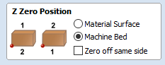
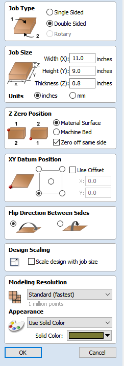
but you said you used a start depth of 0.8" to generate that one, so my guess is you setup Z Zero Position in VCarve as “machine bed” ?
If you did and if maybe for the previous run you had setup/zeroed on the top surface of the stock and kept that zero, then running that G-code would indeed have resulted in cutting air.
The second G-code file has G-code that cuts from Z=0 down to Z=-0.6",
but this time you said you zeroed on the surface of the aux spoilboard: what probably happened is that you left the Z Zero position in VCarve to “Machine Bed”: again, the (probable?) inconsistency between the declared setup and where you actually zeroed resulted in cutting air, because the G-code has the stock thickness added as an offset to all its Z values whenever you choose “machine bed” as the Z Zero position.
If you set Z Zero Position to “Machine Surface”, zero off the aux spoilboard, and rerun that second G-code file, it should work.
@Julien thanks for the quick reply… I think you nailed it-- I have been using “material surface” as the z zero position in all of my “practice” and testing, and now that I used the file from vectric, it indeed has the "zero off same side box checked in the two-sided job setup.
It would make sense that the top worked as expected (again, I’ve always used the material surface for z zero), but the toolpaths from the bottom side did not. I haven’t had the chance to go check but will later today.
I understand your explanation here, but haven’t entirely quite been able to wrap my head around this though–it would seem to me that once I moved z zero down to the spoilboard itself and ran the file that cut from Z=0 to z=-.6" it should have worked. Is the stock thickness offset reflected elsewhere in the gcode?
I agree, if you zeroed on the spoilboard and ran “(alt).nc” file, it should have milled those two 0.6" deep holes into the spoilboard. Maybe just retry running that file? It’s pretty easy to make a mistake somewhere in the workflow when one is caught in a maddening debugging loop, maybe you thought you reset Z zero but you actually didn’t.
There is no other trick related to stock thickness, this is purely managed in the CAM tool (VCarve in this case), when generating the G-code it will add the stock thickness to Z values when you set Z zero position to bottom/bed, and not add it when you set Z zero position to top/surface.
Once the G-code is generated, the machine will move exactly to the positions seen in the file, relative to where you physically set the zeroes using CM. This is why using a G-code viewer is a useful step after exporting the file from the CAM tool: in case you did a mistake somewhere in the CAM project, the G-code preview will not look as expected, and you can go back and check. I like ncviewer.com because after you load your G-code file, you can click anywhere in the preview and it will navigate to the corresponding line in the G-code file. This way it’s easy to check e.g. the Z value for the highest or lowest part of a toolpath, to verify that eveything is in order.
It looks like the “zero off same side” box being checked (thus adding the stock thickness) was the issue. Thanks again for your further explanation-- it does clarify the setting a bit more. Though I am still a bit confused why the second file didn’t eventually work, I also agree with your suggestion that it was caused by being caught up in a frustrating debugging loop.
I was actually trying to do this using ncviwer but wasn’t quite understanding how to best approach it-- your further explanation is also helpful for the inevitable next time…
I managed to get everything cut without any major issues-- always learning. I’ll chalk this up to a mildly annoying way of learning to triple check these material zero settings for two-sided projects. Thanks again for your help!