Im new to CNC so excuse my naivety.
I know itd take more resource, and I love the light, fast, attitude of Carbide Create, Build 43. But, it would be nice to hide/show tool pths during the design mode. I find that when I need to create overlapping geometry for overlapping tool paths, I often check and recheck, edit and re-edit the geometries to match according to different tools. Sure, calculating diameters in my head helps.
My most common annoyance is when I create a shape with many points smaller than #101, 1/8" pointing into my geometry like as in a comb. Or a pocket shaped like a 7 pointed star. I rough the main shape with 101, then clean up the points with a 112. Knowing where the 101 limit is into the vertex would make drawing the 112 geometry much easier. I work a lot of free forms, so copying the small pockets isnt always possible.
Lastly, It would be nice to see where the drill down points are more clearly, instead of just in sim mode. If I could toggle the paths in design mode, I could build a design with shorter tools times, knowing where my cutters will drop allow me to make pockets to final depth before running long runs with depths of +1" to clear. Ive found that with final depth pockets, I can increase all of my drop speeds, decreasing machine time by up to 30%.
Maybe not a biggie, Im learning to intuitively know where they are going to be, (ie bottom left corner) but always check the sim to make sure
Yes I can see the toolpaths, in Toolpath mode. But when I am creating geometries to cleanup corners in Design mode I have no idea where the toolpath limit is for a tools diameter that is larger than a vertex, I need to guess where a good clean up shape should go, test in Toolpath mode and correct. For corners of similar geometries I can copy but with unique corners I have to create new ones every time.
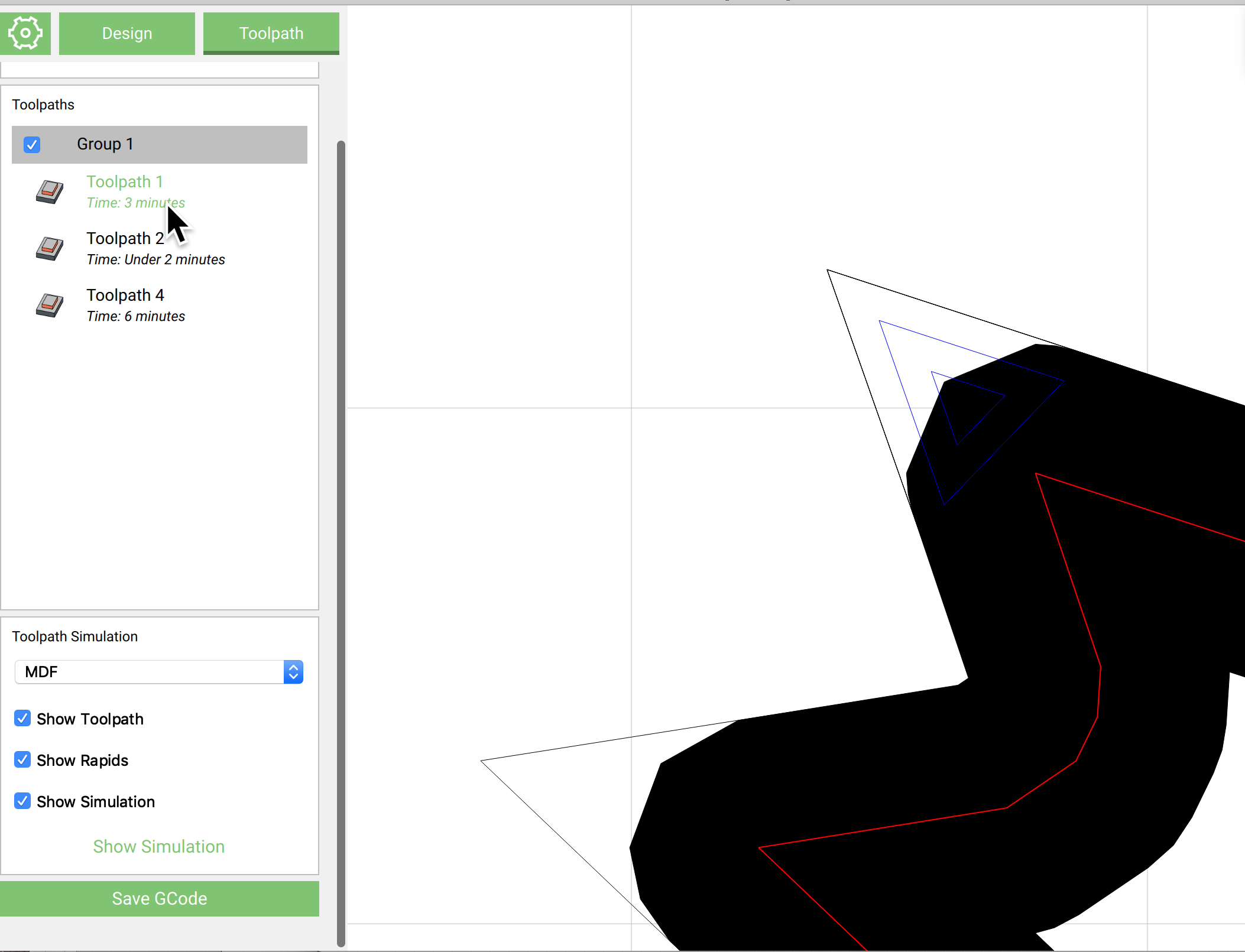
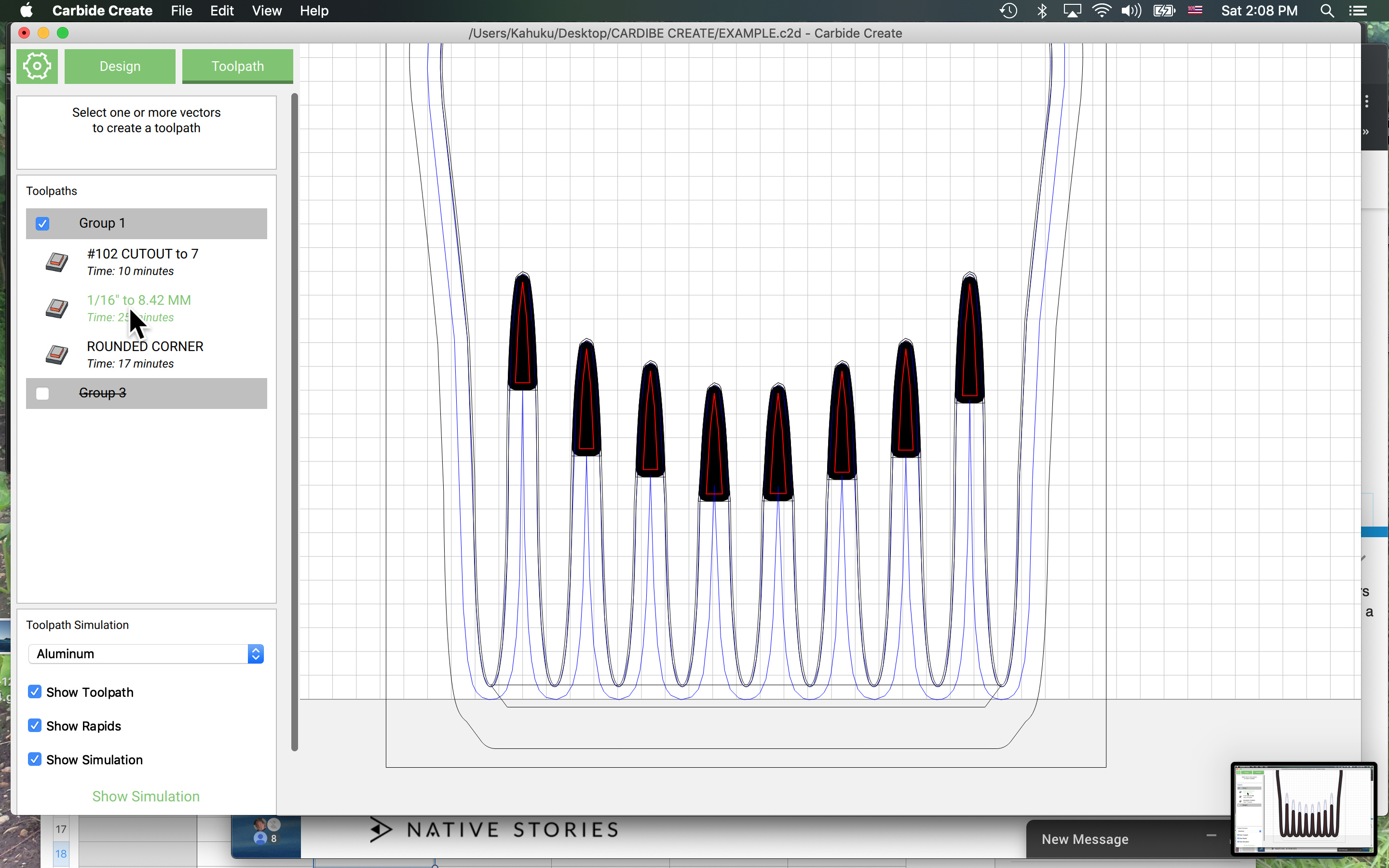
Heres a corner that needs cleanup, visible in toolpath mode:
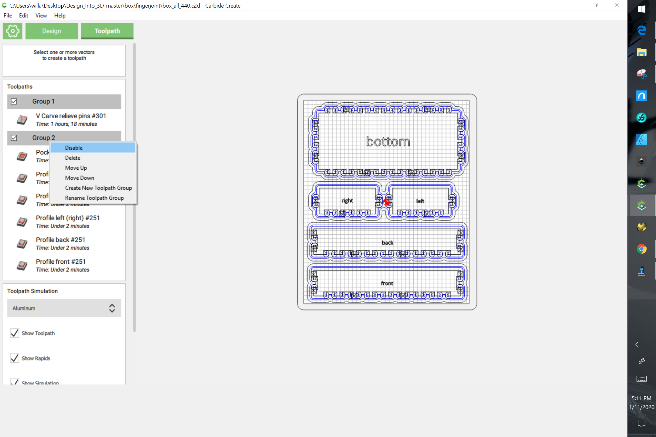
As of right now, I guess where the clean up shape will overlap the tool path for #101, it would be nice to choose to see this toolpath in Design mode. The grouping feature is great in toolpath mode, and yes, if we could toggle the visibility of of its toolpaths in Design mode that would be even better.
the other choice would be to allow 2 tools to be specified in the same toolpath, one for roughing one for fine details
(I’m doing this in my hobby project that creates gcode from CC export SVGs)
Yes, Ive heard of other programs that will automatically choose the best tool for cleaning up corners, limiting the tool only to the needed areas… I wasted lots of time doing entire geometries with two different tools…better to limit the corner cleanup only to whats minimally needed… and in my head a manual designation might be better.
if your cleanup cutter is half the size of the big one you can do an inside contour and clean it all up nice…
the problem with ‘pockets of cleanup’ might be not so nice transitions on the edges
Yes transitions from one cutter to another has been a minor issue… Ive seen variance of about 1/64" but not much more when dealing with everything I do, which is generally shapes smaller than 1" square.
You can inset the path by twice the diameter of the endmill, then offset it by the diameter to get a toolpath which should approximate where cutting will occur — if you’re doing this a lot though, it’d be better to just get a tool which supports “rest” machining.
btw if you want those points to be perfectly sharp, I’d suggest a toolpath where you mix vcarving with pocketing, rather than using a smaller tool… that gets you really nice sharp corners.
basically what you do is (assuming a 90 degree V bit, the math is different for 60):
if you Depth of cut is 0.1", make an “inset” using the offset tool of 0.2" and do a vcarve between your current outline and that inset.
if you do that in addition to your current large pocket you’ll get very nice sharp corners
Yep, I use a 1.64 mm offset for every 1 mm of DOC (60degraa V bit#301) when doing nice clean corners but I dont do that for every design. I have at least two other reasons why showing a toolpath in design mode might help:
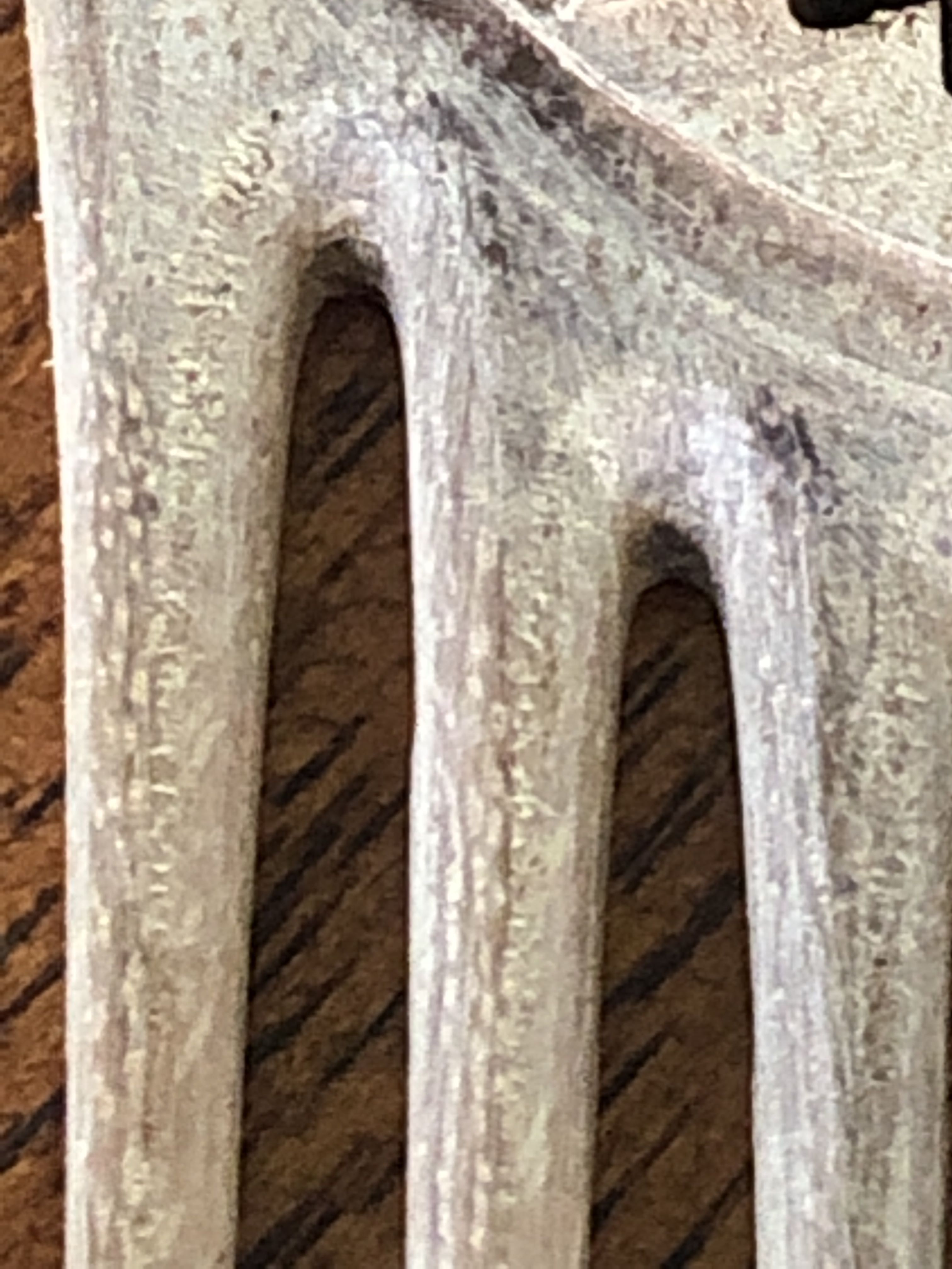
Ex. 1 - When editing a geometry to fit a tool path:
I made the inside teeth with a parabolic path
So I created am inside pocket to clean it up but when I use a roundover cutter
with a .2mm outside contour path, it wont align with the #112 toolpath, so I needed to change the geometry to match the toolpath of the #112 cutter:
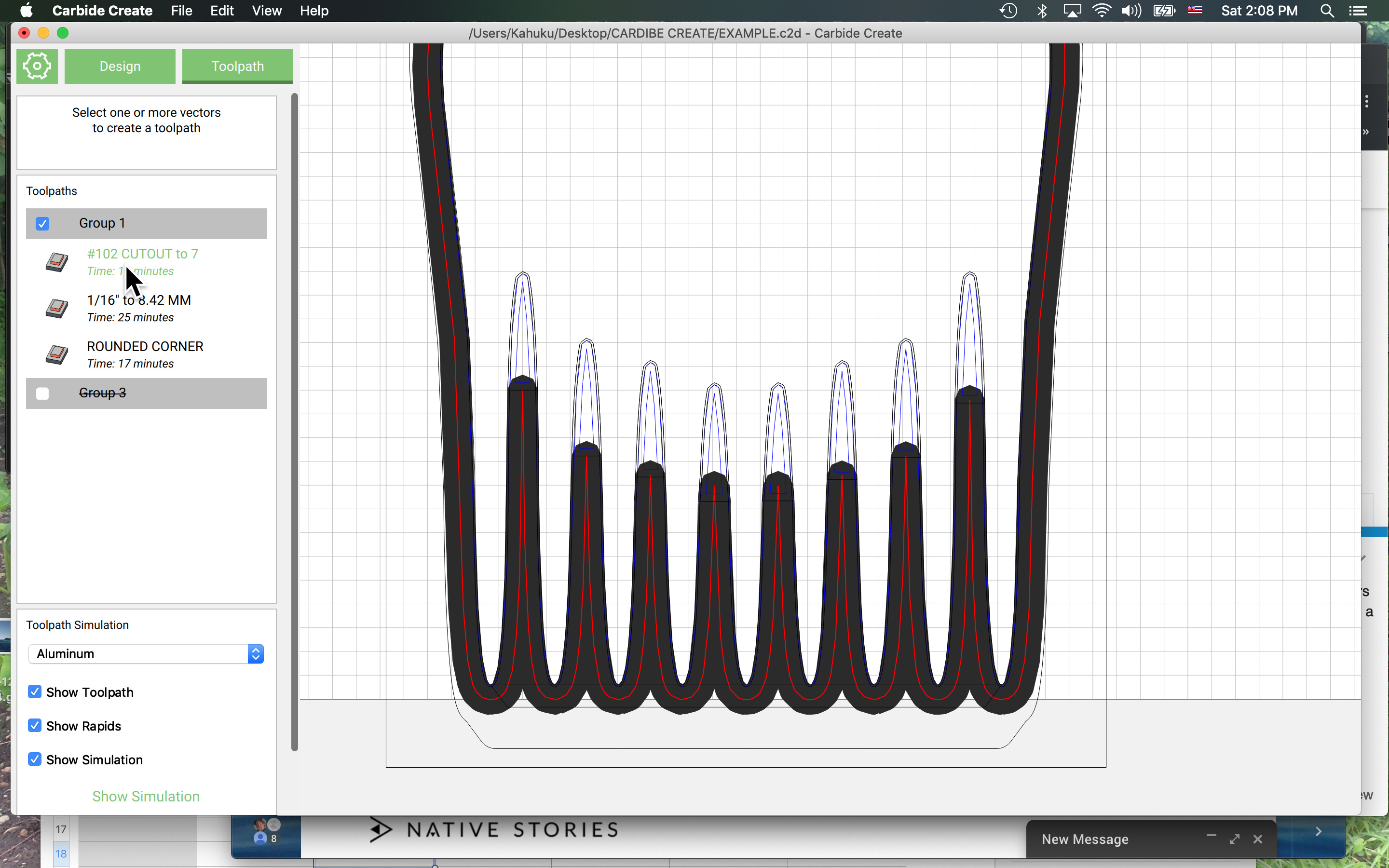
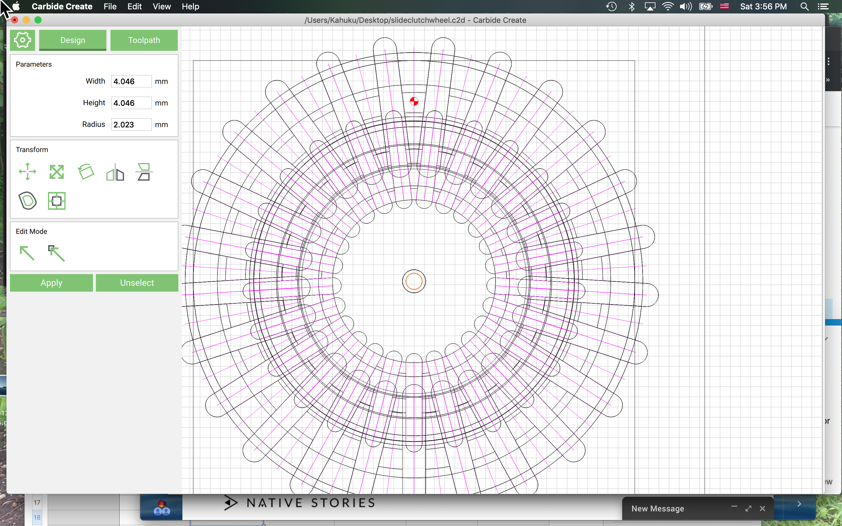
As Will mentioned earlier, I could use the radius of my intended tool to create a outside contour, which will show me where my new geometry should include. In Example 2 (below) I have multiple overlapping shapes, which all need at least three tools per shape. I calculated each one the way Will described, and it works well. I just wonder how much faster it couldve been if I didnʻt have to calculate each path. With a visual reference, I could create my rough paths dynamically.