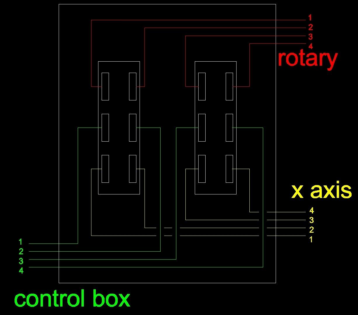
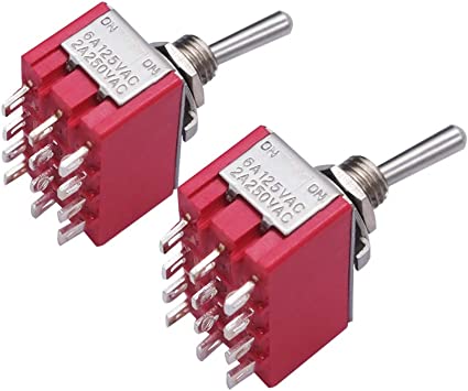
Hi, I would like to hook up two stepper motors to a switch so I can switch from one motor to the other. No speed control or anything, just switch one off and the other on. The picture shows the switch and the layout of my two stepper motors. What I am trying to do is have the switch between the rotary axis and the X-axis so I can switch to one or the other. Thanks for your advice.
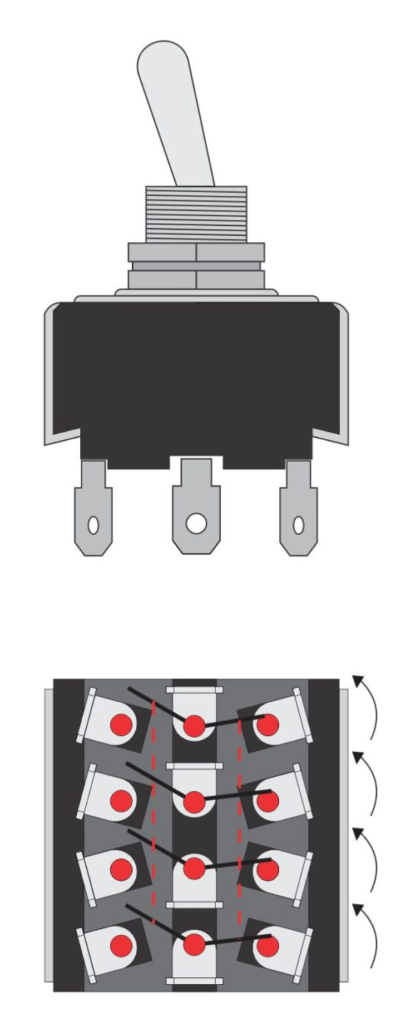
I think what you’d want is a 4pDt switch (four pole, double throw). That will make the wiring simple.
Always make sure you power down when you’re switching.
You only need a DPDT as you only need to switch one side of each motor coil to one motor or the other. The other side of the each motor can be connected together permanently.
Same amount of wiring but gives wider choice of (and cheaper) switches
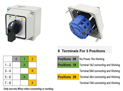
Hi Neil, I have this switch already, Universal Rotary Changeover Switch SZW26-20/D202.2D is this what you are talking about? I am not quite sure about the wiring and will try and play around tomorrow and if you don’t mind report back to you. Thanks for your time.
HI Jason. I have already the switch witch shown in my pictures. I will try to make it work with that one. I have no experience with electronics at all and I am very thankful for all the help I am getting.
No, but you can make it work with that switch. Do you have to use that switch? I’m on my phone, but I can try to draw up a diagram tomorrow for that switch, similar to what @flynnjs suggested.
The reason I suggested a 4pDt switch is for ease of wiring. Stepper coil signals from controller to the center, gantry stepper to left, rotary stepper to right. I can’t see a reason for a third, off position, so I’d get an ON-ON switch.
Like I said, you can use the switch you have if you want.
Connect A+ from controller to A+rotary AND A+gantry.
Connect B+ from controller to B+rotary AND B+gantry.
Connect A- from controller to pin 1 AND pin 3 on switch.
Connect B- from controller to pin 5 AND pin 7 on switch.
Connect Pin 2 to A-rotary
Connect Pin 4 to A-gantry
Connect Pin 6 to B-rotary
Connect Pin 8 to B-gantry
I don’t have a switch or a rotary axis or the time to test, so double check my logic. (Maybe @flynnjs can check too)
Sorry I didn’t have a chance to make a diagram, but it probably would have been less clear than my notes above.
EDIT: If you do get the 4pDt switch, I’d consider finding one with screw terminals…save you from desoldering when your rotary axis spins the wrong way.
I returned my first switch and the 4pDt switch is on the way!! ( Amazone works fast )
I really appreciate your help very much! And like the old saying is " shoemaker stick to your shoes". Electronics is over my head and I really wanted to dry something different with the rotary axis!
Give me some time and I will post my first project. It took me a while with a lot of help from different people, but I will get there to get my first rotary job done!