I bought a Shapeoko 4 Pro last year. I’ve made a few projects with it, but it certainly doesn’t receive heavy use.
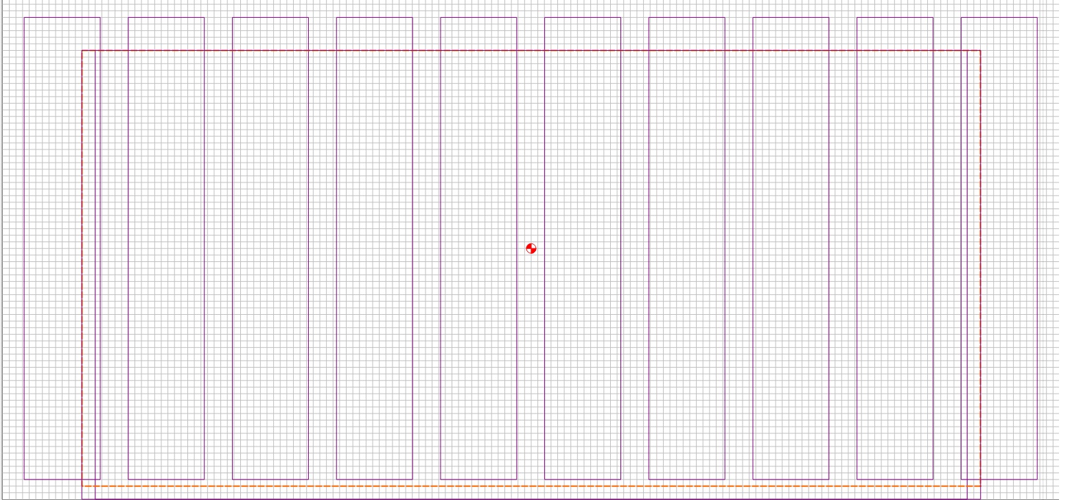
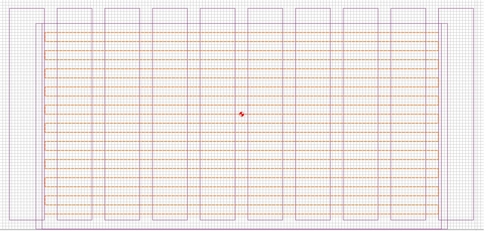
The MDF slats are kindo of beat up for lots of reasons. Decided to do the flattening thing using McFLy. I attempted to get an idea of how off-flat it was by using the jog function to try to find Z -0- on all the MDF slats. It appears that surface varies by as much as .02". Approach is to do a border pass, as shown in Outline.jpg, around as much of the base as the bit can reach. Then do a Left to Right and back pass partially overlapping that outline. That’s shown in Interior.jpg. The passes overlap by a 1/4". Depth of cut is .002". Feed rate is 125 - 150 IPM. I’ve set the router to its lowest speed, occasionally bumping it up to a “2”. I’m getting a visible furrow along every other row. That means that at 1.5" intervals I can take a clean sheet of paper and butt it up against the “X” path. When I run my finger along that paper-MDF line, I can barely feel it, which makes me thing that the router is tilted slightly toward the back. When I try using the Jog function on one of the slats to run similarly spaced passes front-to-back, I can barely feel the rows.
Absent good machinist tools other than a caliper, what do I do to correct this, or is the difference too small to try to remedy? I certainly don’t want to swap a front-to-back tilt for a left-right tilt.
Another Question: Any guide to how long before I should need to replace the bearings? I’m used to Bosch 1617 that I use in a router table. It gets much harder use and the bearings seem to do me for at least three years.
Search for framing on the forum. There are lots of posts and lots of opinions.
Usual process is to flatten the MDF as the router sits and then tram and then flatten again.
There are home made tram gauges shown in various posts. I tried a few but wasn’t happy with my results so I bought the SST mini tramming gauge and a “super flat” piece of glass for the process.
I wish I could answer how much is enough on tramming, but I got it a lot better and am happy. It could probably be even better.
I used the method of inserting feeler gauges behind the Z mounting plate to adjust front/back angle. I felt like that approach was a lot easier than loosening the bolts on the rails and twisting.
“How close…?” is subjective. It depends on the type of work you intend to do, and what tolerances you want to hold.
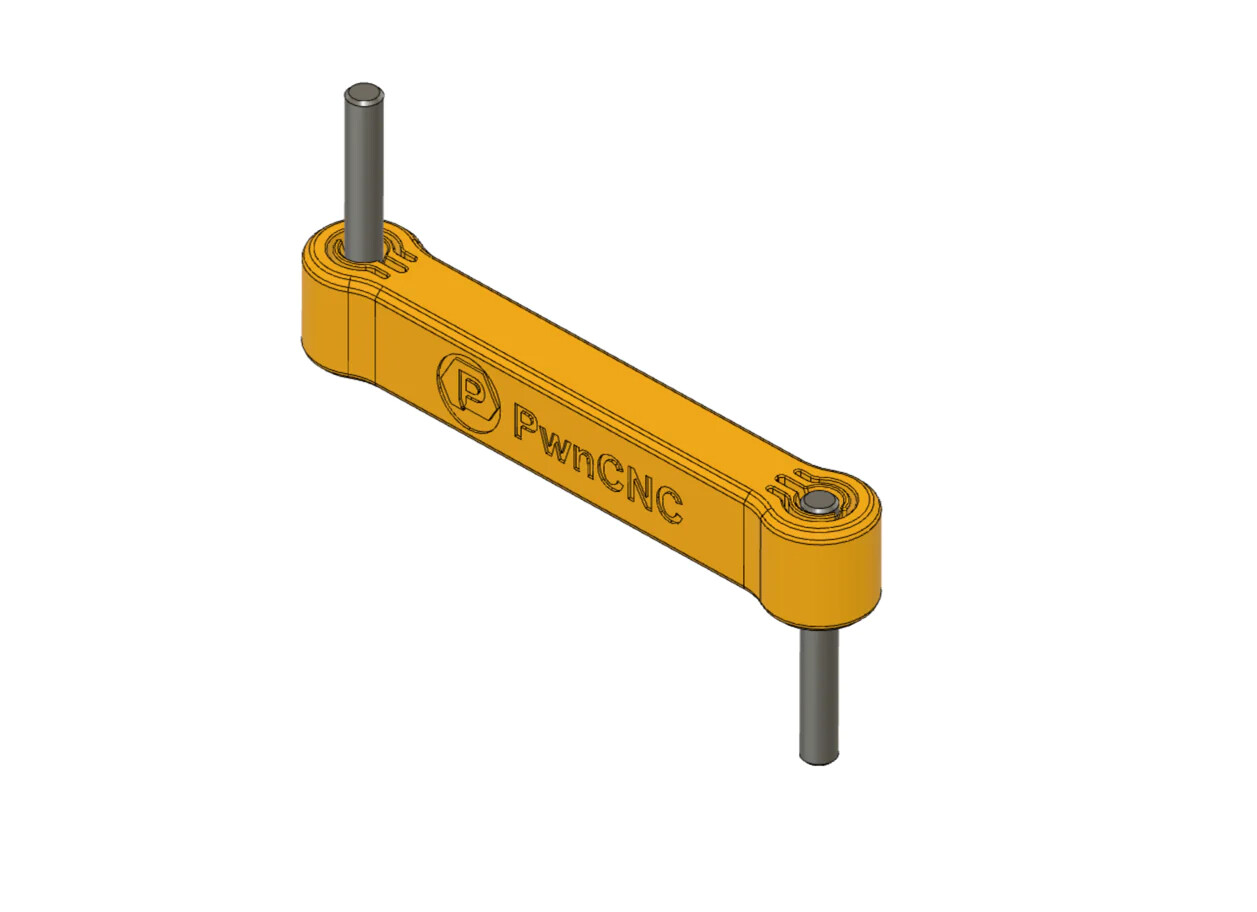
The simplest (and cheapest) type of tramming tool is a tramming arm. Any rigid bar of hardwood, aluminum, or a rigid plastic & 2 dowels. It doesn’t have be built precise or accurate at all. The only thing that matters is the dowels don’t move, and the arm doesn’t flex.
So to check the front to back tram, insert one dowel in the spindle & point the arm forward. Move the machine head down until the lower dowel just touches the table & zero your Z axis.
Now raise the Z, spin the arm pointing toward the back, and move it down until it just touches.
Read the difference by the current Z value on your readout.
When you get your spoilboard leveled/replaced try using the bottom of material. It is a change of work flow but I replaced my spoilboard in Oct 22 and there are barely any wear on it. I use bottom of material and use the BitZero to zero Z on the spoilboard. I will use top of material for projects that do not cut through. The bottom of material has given me good results an a lot less cut through to the spoilboard and a lot less cutting onion skin off projects that do cut through.
The change of work flow has to be thought out. I often set my zero in the center manually with a vee bit and then jog off the material to set Z zero. About 90% of the time I use the Jog menu Rapid positions to check my X and Y zero and have to remember to jog off the material to do the Z+6mm to check Z. After you get used to doing that it is easy. Just dont leave the Z over the material and do the Z+6mm or you will hit the material with the router bit.