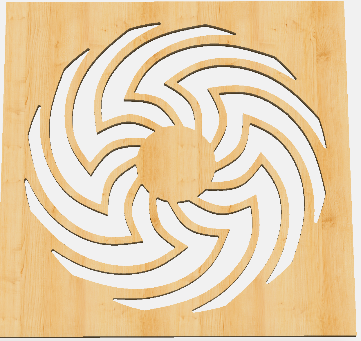
On the Nomad and running into difficulties. The end goal is to use aluminum but I can’t get it right with hard wood so let’s start there. The desired thickness is 4mm, with width / height at the max that can fit in the Nomad (20cm I believe). I tried screwing the corners to the waste board, and also putting a screw in the middle, but once the drill got towards the bottom of the stock, the little arms snapped because they’re pretty thin, around 10mm closest to the center.
I thought I’ll try putting supports between the arms at various points, but then I’m not sure how I’ll get them off once it’s done.
I tried double sided tape, it was fine on the top layers but when it got to the bottom it broke.
Also like I mentioned, tried putting one screw in the middle and 4 screws in the corners. In MeshCam I set it so the machine won’t cut the corners, basically keeping the 2 arms in each corner connected to the material, with the material screwed to the bed. Broke as well.
re-draw it to create the inner portions as pockets
cut out the pockets
have a large washer just a little bit less than the diameter which has holes in it — if making multiples have a fixture with matching holes — fasten the large washer in place after cutting the pockets
If it’s thin enough you could use an inside profile rather than a pocket — or you could insert the inner profiles and cut the geometry pairs as pockets if chip clearing is an issue:
If I’m following you (sorry, still weak with the terminology): first the drill will go inside the shape, but when it’s done, the shape will still be attached to the material at the perimeter. Then I press the shape against the bed with the washer, which makes sure the arms don’t break, and remove the perimeter (basically the four corners). Is that how you meant?
Dumb question: what is the difference between a pocket and an inside profile? How do I do one over the other in MeshCAM?
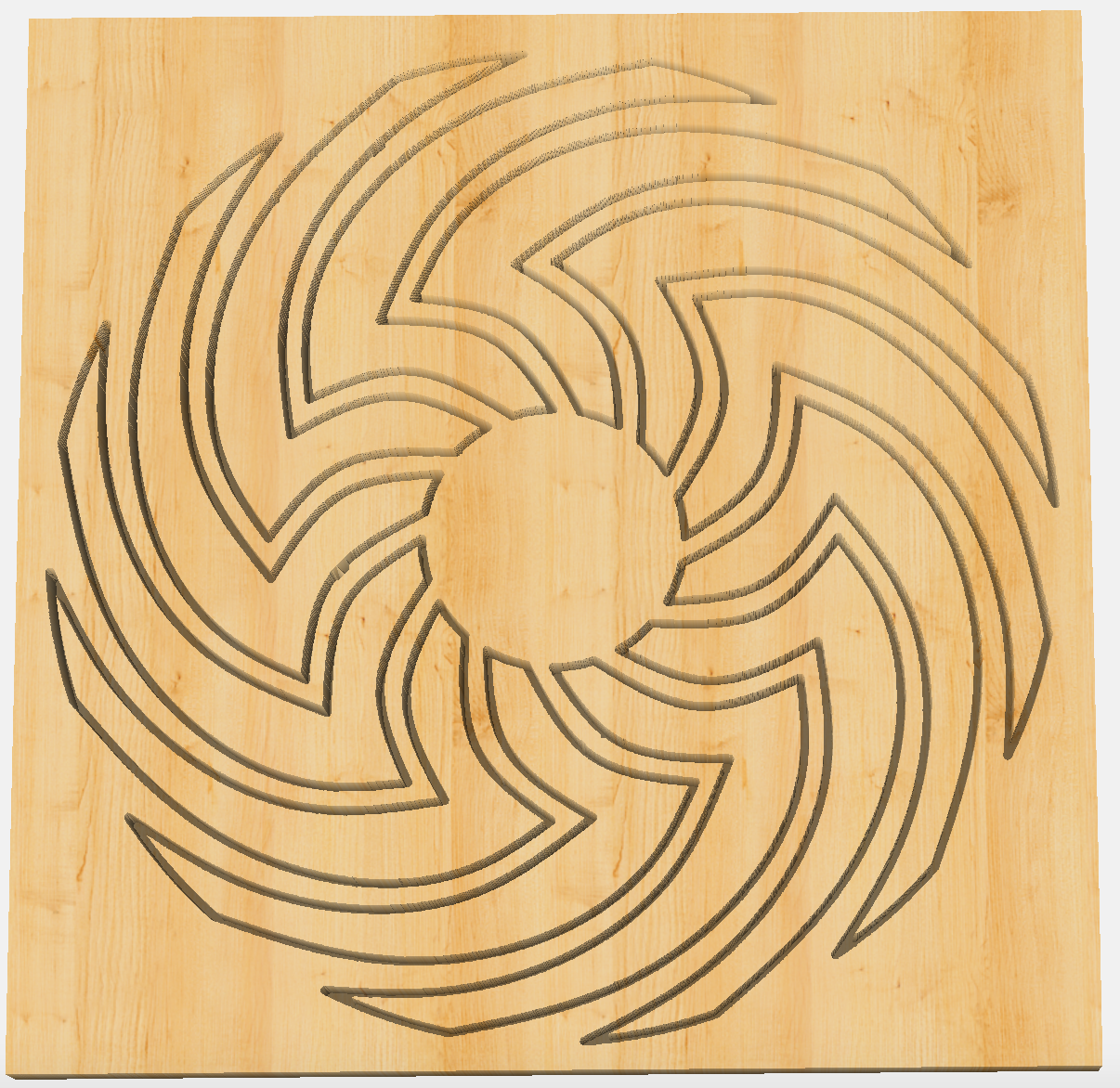
How would I go about generating the tool paths for these cuts? I was thinking of creating an svg of the inside of the shape for the first cut (red), and a 20 cm diameter circle of the perimeter for the second cut (green). Then, once I get to the second cut with the washer on, how do I ensure the tool doesn’t go near it? Is it enough to watch the generated path in MeshCAM and see that it only moves in the perimeter?
The terminology I used is from Carbide Create — I believe this job is simple enough that it’d just be much easier to do in Carbide Create — you’ll get hopefully good enough toolpath previews there.
In some materials, slotting can be hard — that’s why I mentioned adding some geometry to cut it as a pocket while maintaining close to the speed advantage of the second inner profile cut.
If you don’t have problems w/ chip clearance (material is thin) then the second option is the one to go for.
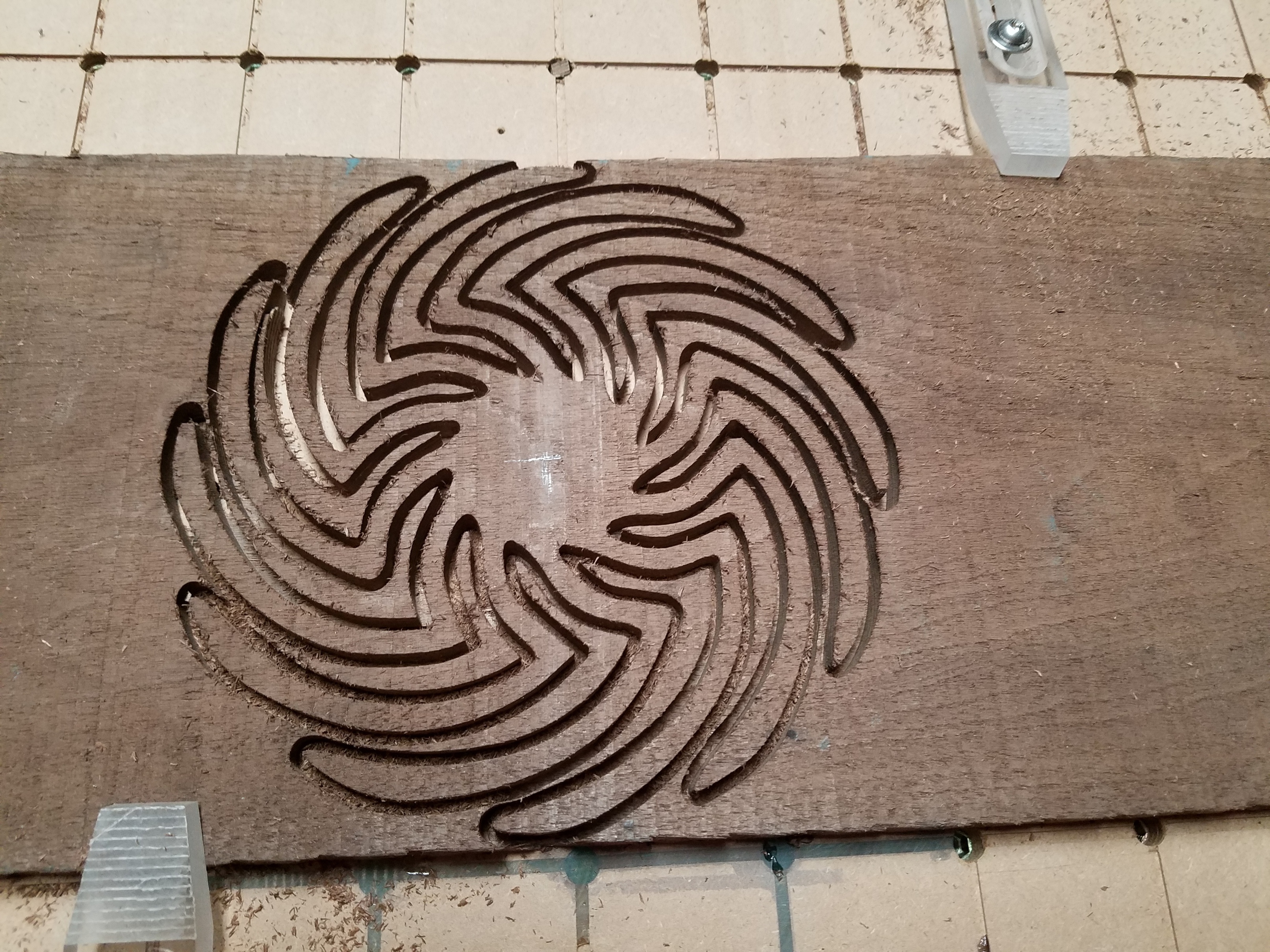
Ok, I got bored. This is walnut cut with 1/8" bit in .513" stock {I know it,s thicker, all I had}.
I left a light skin on this piece of .005" it worked well.
If I was cutting this out of aluminum as you had mentioned I would try super glue as a work hold solution. G/L Ray
That looks surprisingly good. I guess the 1/8" bit is too big to make the sharp turns near the center of the shape, because it’s not as round as I expected.
Well you’re half way there… to finish the piece, do another one and place it anti-symmetrically to the first. Then turn them in different directions to get the full effect! http://codepen.io/idank/pen/dvjdPb