So I spent a couple hours tramming my spindle after installing my new machine table. On the Z-Plus, the left to right tilt is not easy to tram but doable.
Suggestion to the Carbide 3D team:
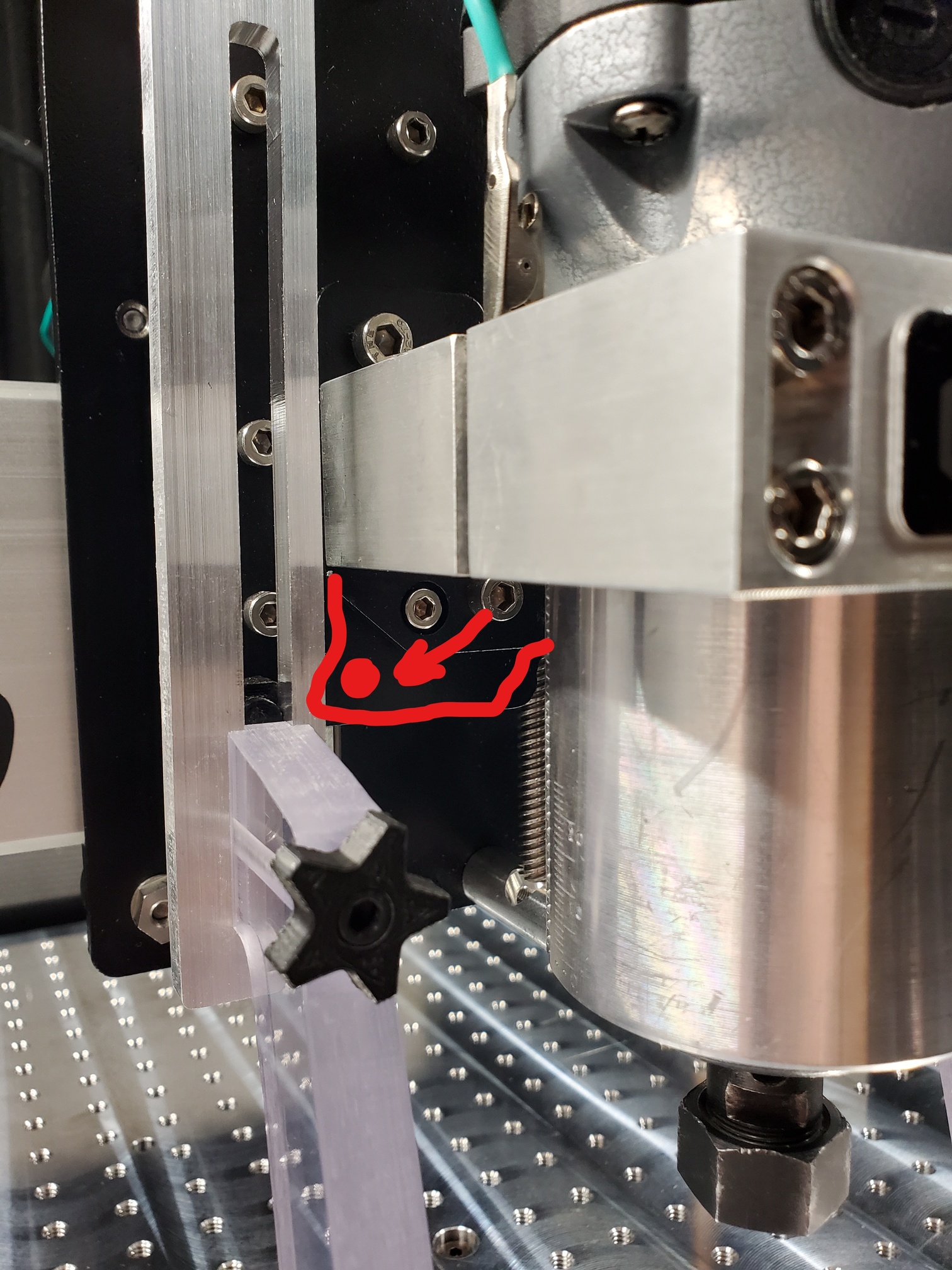
Please adjust this plate and move this screw. You cannot tighten it when the spindle is in the mount which means when trying to tram it, you constantly have to take the spindle in and out. This is not a great experience.
However, nod is incredibly difficult. I am looking to get the whole Z axis to be perpendicular, not just the router mount. I could just put tin foil under the mount but that doesn’t truly square the Z axis since it would move forward or back when changing height. This matters to me because I bore many small holes in aluminum often and I have found that it is really easy to break tools if the tool is being pressed into the side of the bore as it is cutting. Has anyone figured out a good solution for tramming spindle nod? I currently am using varying size washers and foil between the top V wheel and the Z plate. I have also tried loosening the screws on either end of the carriage and tilting the whole X rail but found that to be unreliable.
The tramming plate thickness and spindle mount should be machined well enough that the problem causing being out of plumb along the Y-axis is usually the Delrin V wheels or the gantry — have you checked them?
If the problem is the tramming plate putting a bit of foil at the top or bottom usually works.
Thanks for the tip but yes, I have checked my wheels on both x and y and the gantry itself. They are in good shape. It is already pretty close to square before all my fiddling. Unfortunately, small tooling and boring ops means any tram issue is magnified. I did end up getting it even closer, probably good enough. I just wanted to see what other people have done.
Even with the HDZ and the ‘big clamp on the X rail to rotate it against the weight of the Z axis whilst you tighten the bolts to the Y plates’ approach I found that, when I had V wheels on the Z I still couldn’t get enough adjustment to bring the Z to vertical.
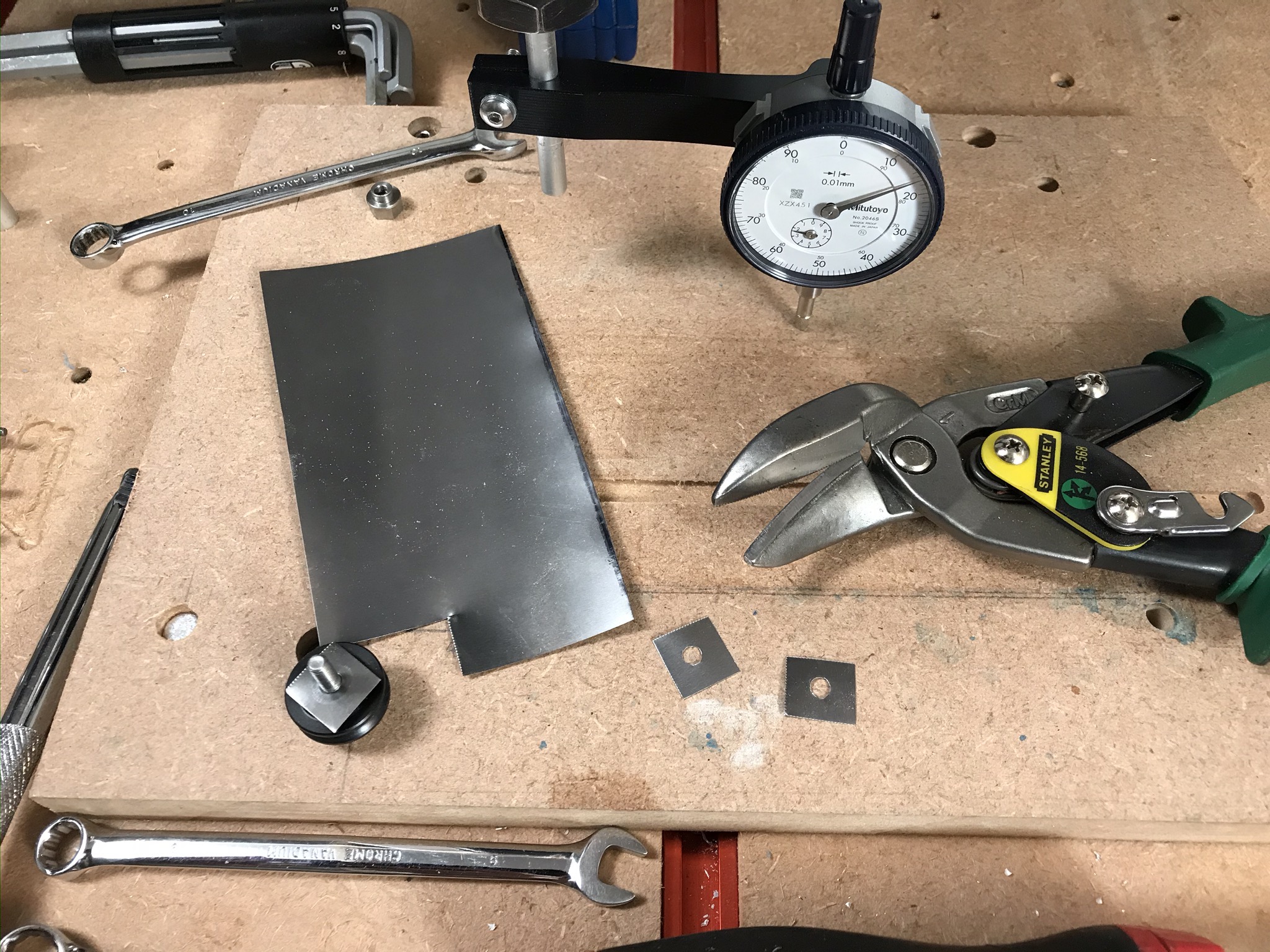
In my case I measured the offset and then cut small matching shims to go behind the lower V wheels to bring the Z to vertical so that the Z rails were vertical and in line with the spindle. It seemed pointless to me to adjust the angle of the spindle out of true with the Z movement, I’m trying to tram the machine in not tram it out