Yes, I like to make weird (odd) stuff…it’s what a retired engineer does during a stay-at-home pandemic. So I’m on a path to make some tiny V8 Engines, but I thought I’d start with a simple Briggs and Stratton 3.5hp Go-Cart engine. Ok, it’s proving to be not so simple. Tiny things are HARD to make…
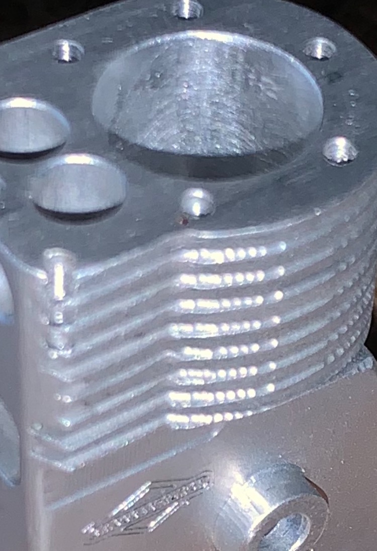
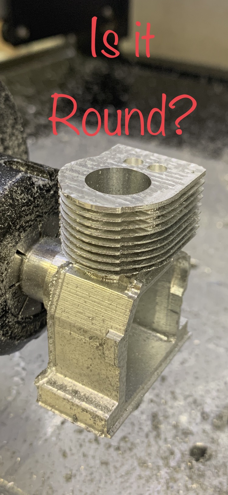
Now onto this problem. The block’s cylinder bore needs to have a REALLY Round hole. Let’s first take a look at what a (my) standard Shapeoko (stock, set at 40 steps/mm) made on the first attempt. Well, it looks nice…
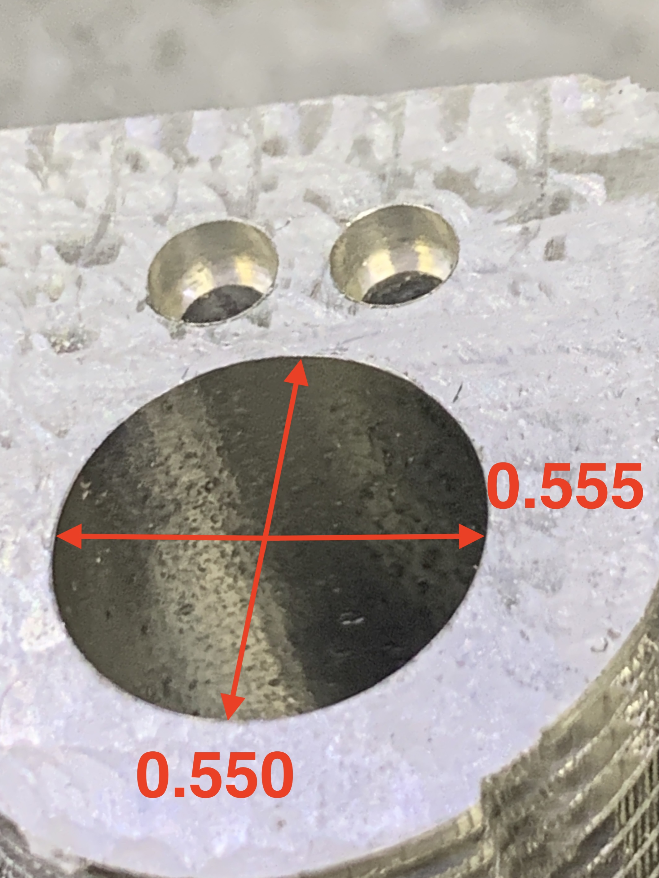
Let’s take a closer look…
In the Y+/- Direction it measures 0.555"
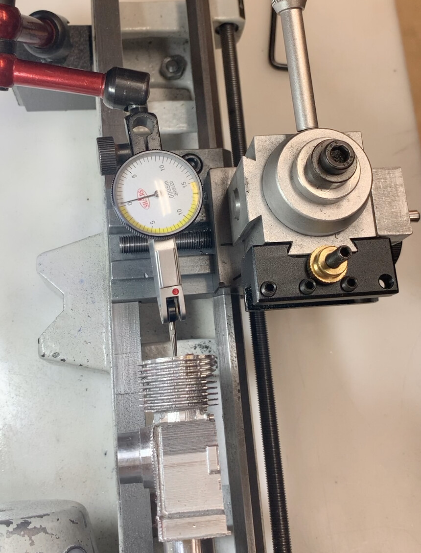
But in the X+/- direction it measures (0.550") or 0.005" smaller (0.0025" per side)
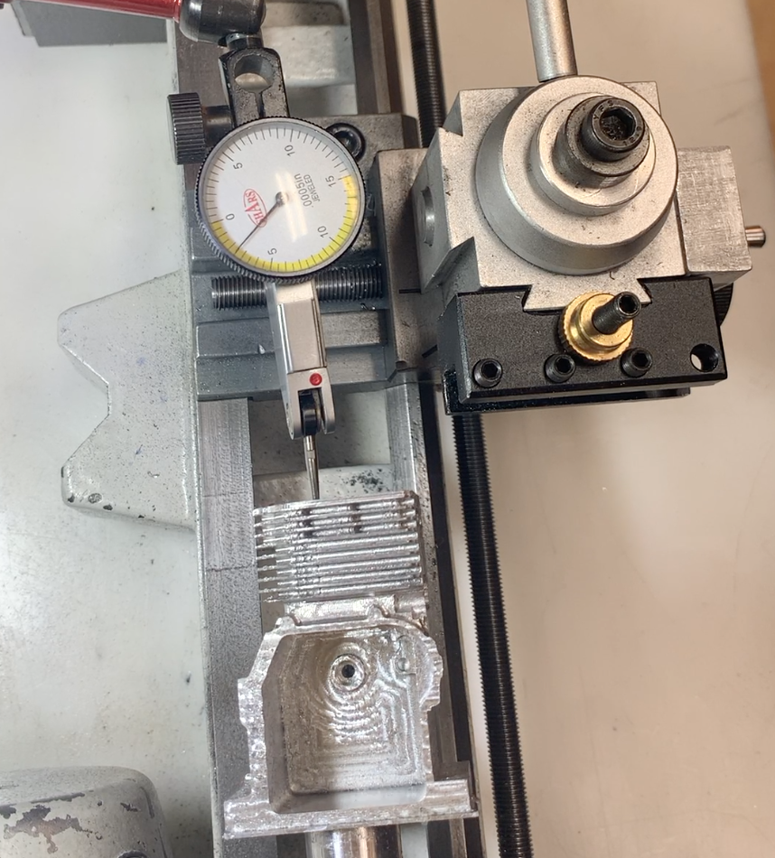
Note: the 0.550 Dim, is in the X+/- direction (when in the Shapeoko)
This actually surprised me because I normally see bores within 0.002" My machine isn’t out of adjustment, I just picked a bad (perhaps the worse) spot on my table/machine.
Meaning I have mapped my entire 16x16 table, and I have areas that cut larger, smaller, and some areas that are spot-on. It’s typical for timing belts, and since my machine has large AND small cutting areas, a belt calibration will NOT fix all the errors (understand?) But the fix to cut a really round hole is the same.
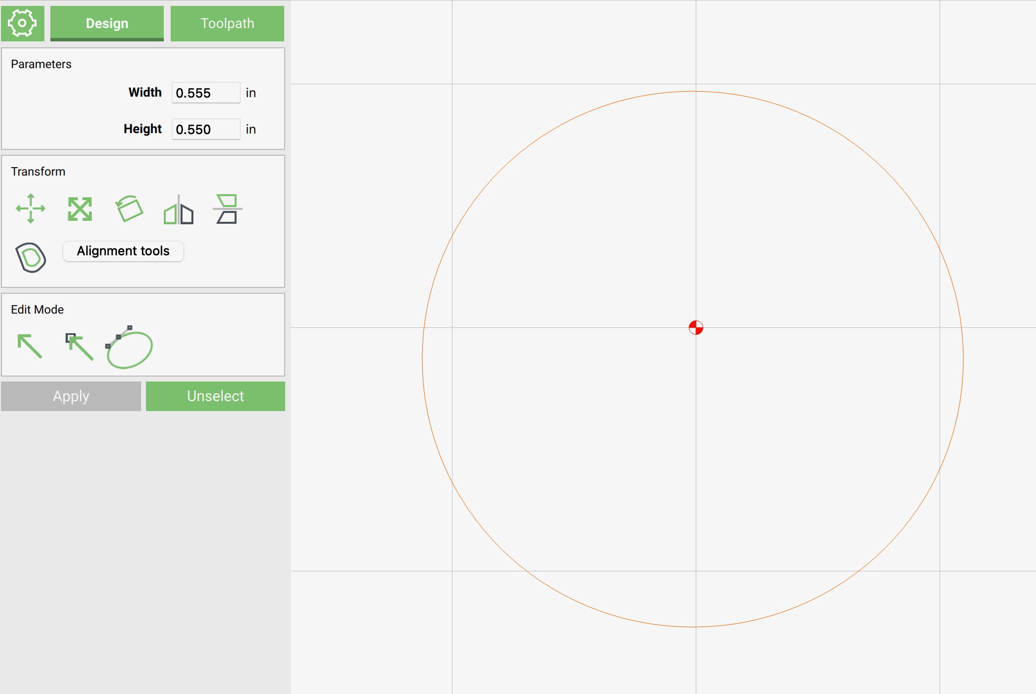
I open Carbide Create and draw an ELLIPSE (circle feature) that is 0.005" LARGER in the X-Axis, to force the Shapeoko to actually cut a round hole. Sounds odd? Perhaps, but it works. See how the Width is 0.555 (X-Axis) and the Height is still 0.550" (Y-Axis)? But THIS geometry will cut a 0.550" Round hole on MY Shapeoko, at the present X0 Y0 Location.
NOTE: Sometimes the machine will need an extra 0.001 to “get it there” so some trial and error (or cut, measure, adjust, repeat) helps.
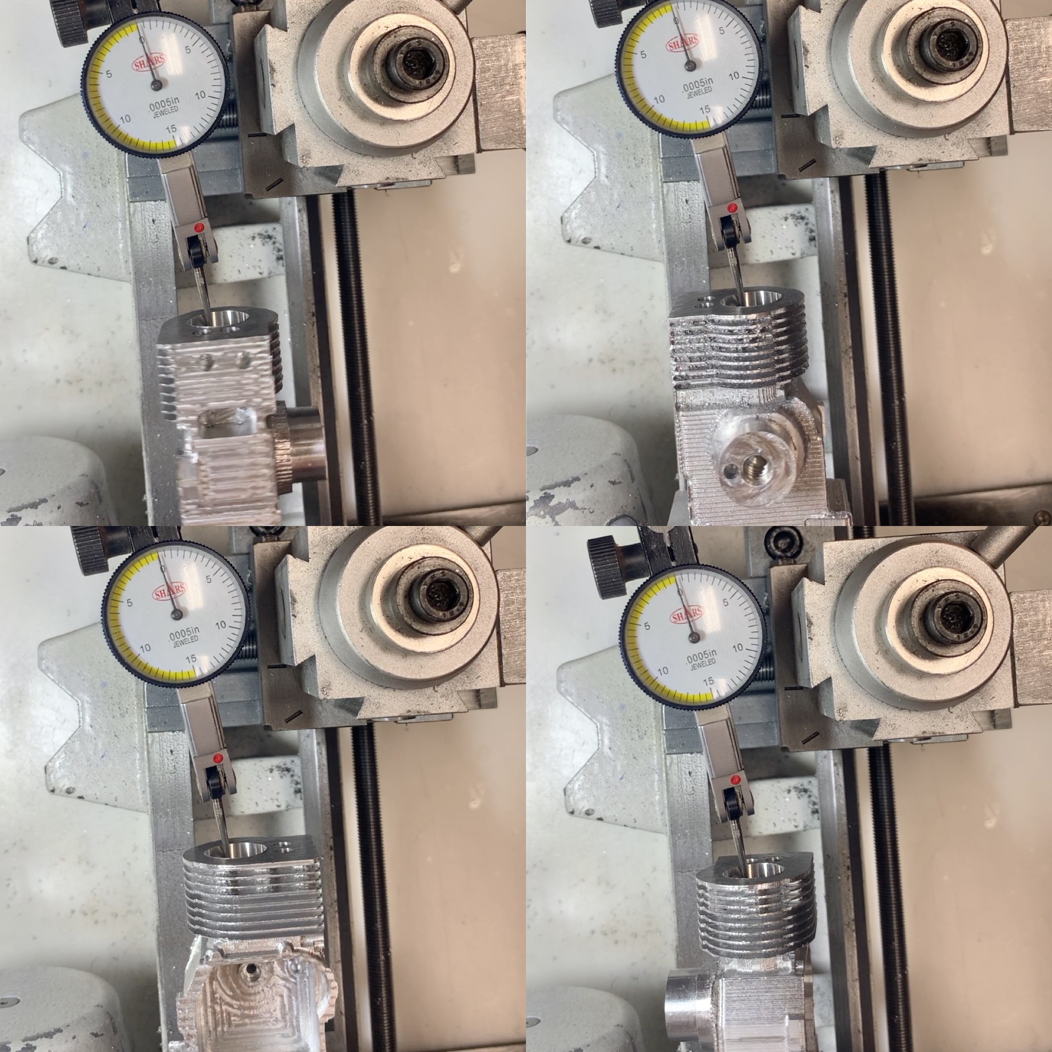
I then measure the bore and opened it up to 0.555" (Final dimension) using the same principle. (You can also do this in Fusion and use the Leave Stock feature rather than needing to draw additional ellipses in CC, same results)
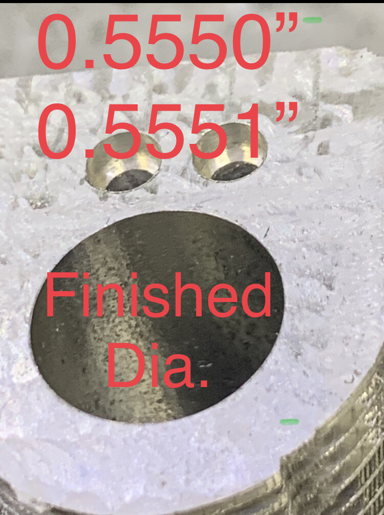
Finished bore:
I have been using this method for 5+ years on my standard Shapeoko, and never really fully explained it step by step here on the forum, and thought I’d share my method today.
Do you have a different method/tool for creating tight tolerance parts?
I hope you learned something today, and if you have any questions, feel free to ask…I’m here to help.
NOTE: While I may have a 4th-axis setup on my Shapeoko, I am still running Carbide Motion to drive my Shapeoko, I have a separate controller to operate the Rotary (4th-axis) so that I can machine 4-5 sides of my part without needing a different setup.
NOTE 2: You can use the proven method to cut accurately ANY type of feature, ID, OD, a box, letters (inlays) etc…