After reading a bunch of suggestions and watching some videos, I decided it was time to try to tram my Shapeoko 5.1 Pro with the 110v spindle. I originally was going to attempt to use a tramming bar to do things as precise as possible, but after watching a video on youtube, I decided to go a much simpler and more accessible route.
Equipment I used:
- Sheet of glass thick enough to be pretty stable with weight on it. In my case it was a mirror tile I had from an old project
- 2x 1x2x3 blocks I bought off Amazon (Precision 1 x 2 x 3 Inch Blocks 23 Holes Accuracy 0.0002 Inch Suitable for Milling Machines for Setup, Layout and Inspection Jobs 1 Pairs: Amazon.com: Industrial & Scientific)
- A cheap set of feeler gauges I bought off Amazon (Amazon.com: Spurtar Feeler Gauges 0.001-0.04" (0.03-1.00mm) 32 Blades Tapered | Dual Marked SAE and Metric, For Spark Plug, Valve, Piston, Guitar, For Measuring Gap Thickness Width : Industrial & Scientific)
- Optional but very helpful: set of t-handle metric allen wrenches. These are very helpful since you’ll want to really tighten all the screws as you’re tweaking things and a normal allen wrench will be hard to get all the way into the holes
- A board you can fasten down to use to check your progress
- Whatever your flattening bit of choice is. I have a pretty cheap 1" diameter one I got on Amazon. I don’t know how perfectly flat it is, but because of the bit rotation, it should still show if the spindle is off at all.
Where I started
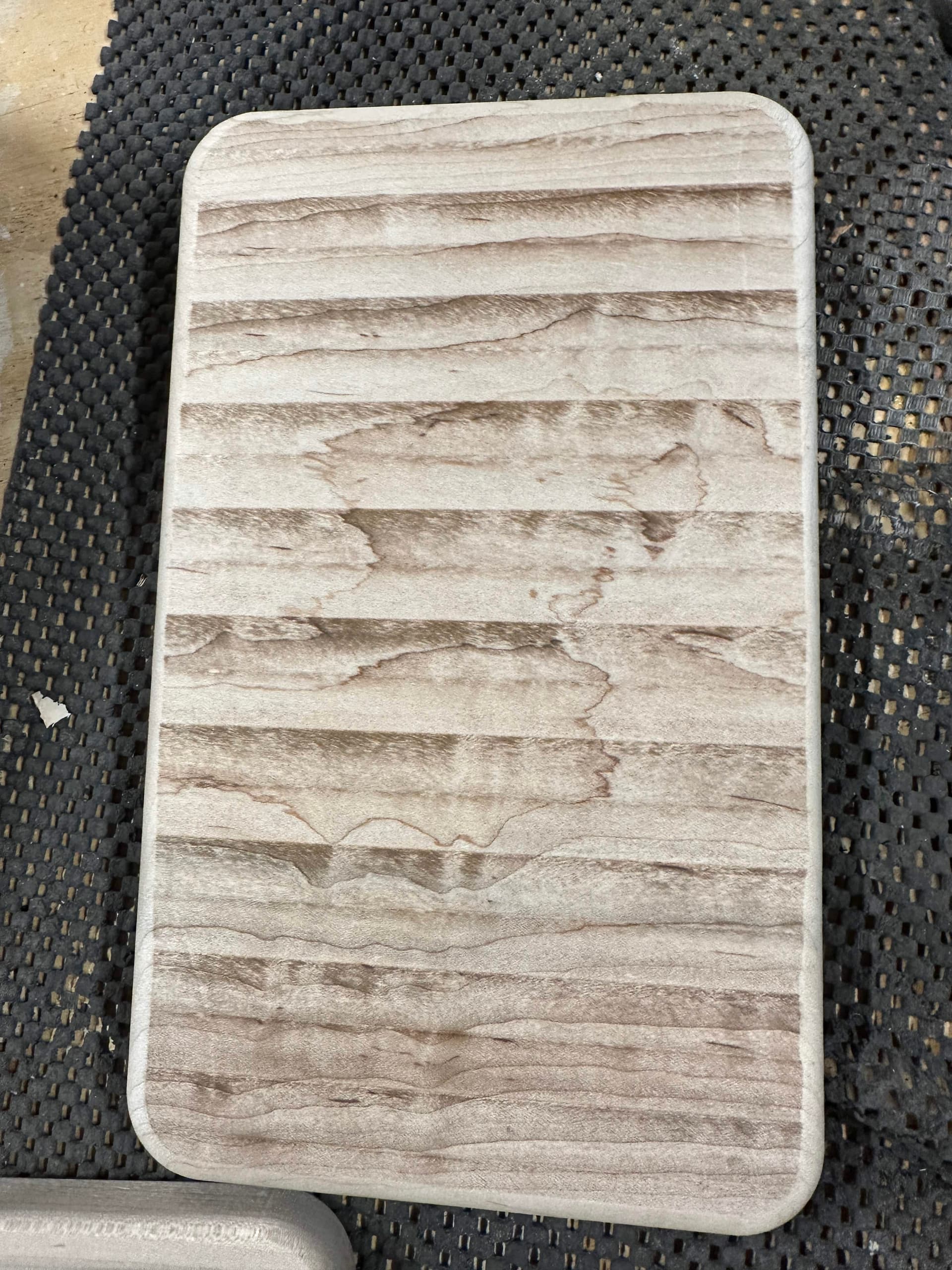
This is a board I did recently where you can pretty clearly see the lines and burning from the flattening process. The lines are easy to feel as well and it took a bit of time to sand out all the markings.
The process
First I brought the spindle to the front center, removed the bit, and disconnected the control wire. Don’t forget to replace the cap so any dust that might be floating around stays out

Next I went ahead and removed the spindle from the mount by loosening the two silver screws at the front of the holder. BE CAREFUL! The spindle is HEAVY and you need to have a hand on it so it doesn’t just fall out the bottom.
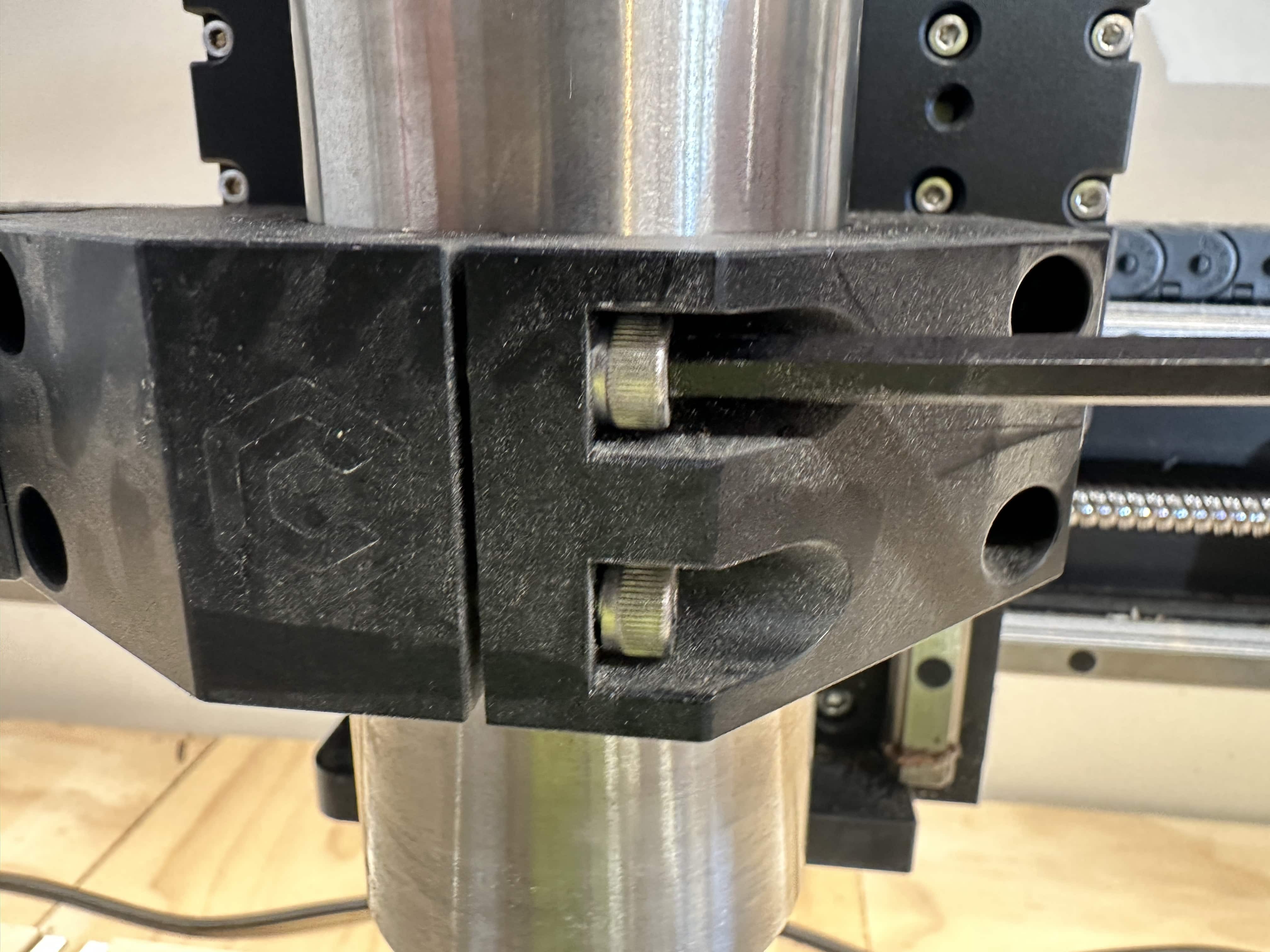
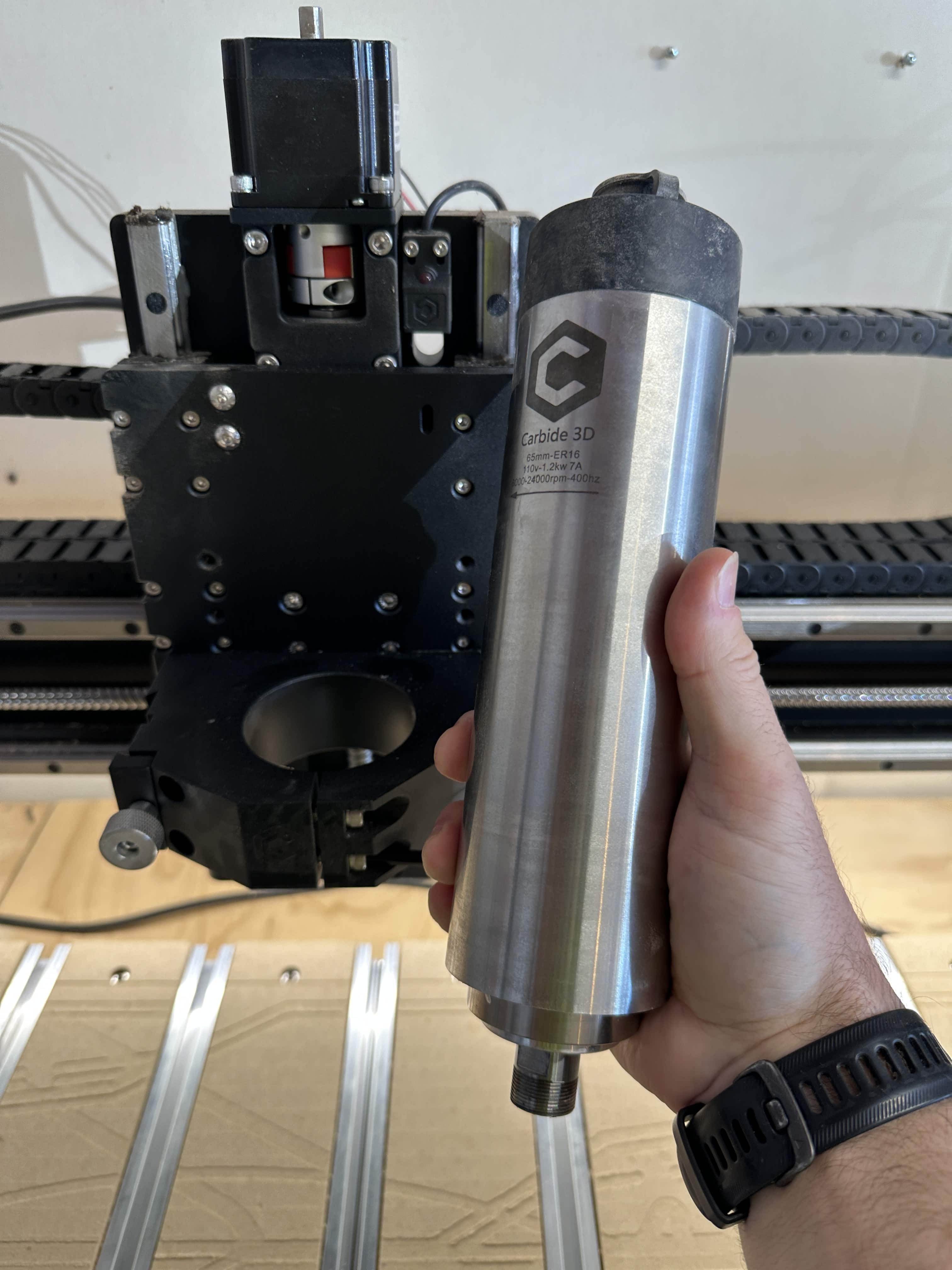
The next thing I did, which is totally optional, was to verify that the holder was, in fact, not flat before I did anything else. The last thing I would want is to go through all this only to discover that the problem was something else and I potentially made things worse.
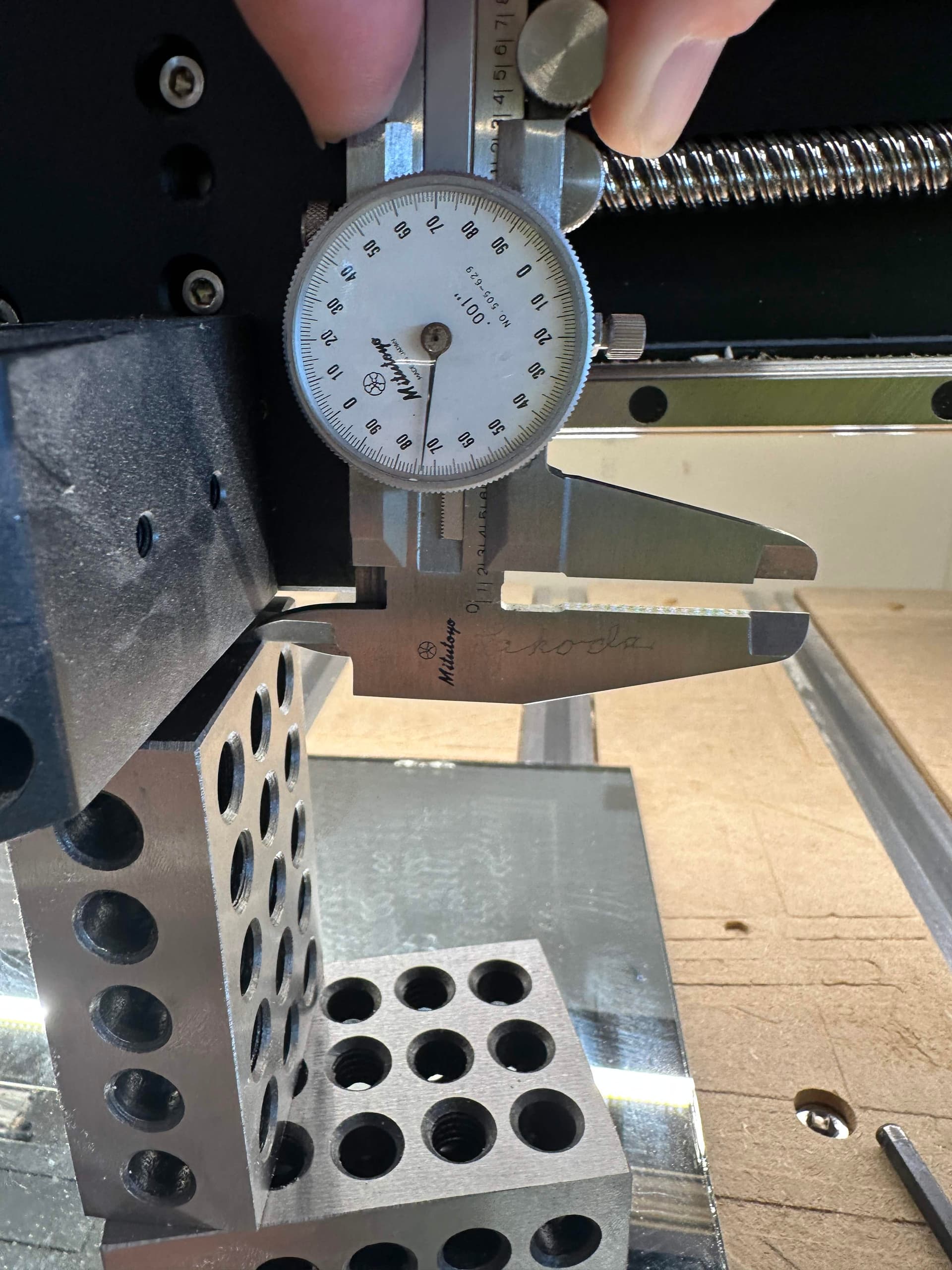
I put the glass down below the z-axis and put the two 1-2-3 blocks on it so that they would be tall enough to reach the axis when it was lowered. Next I lowered the z-axis so that the spindle holder was just above the two blocks but not touching because I wanted to measure the gap. At the front, I could measure a gap of ~0.165" and at the back I could measure ~0.175". So there was definitely some tilt involved.
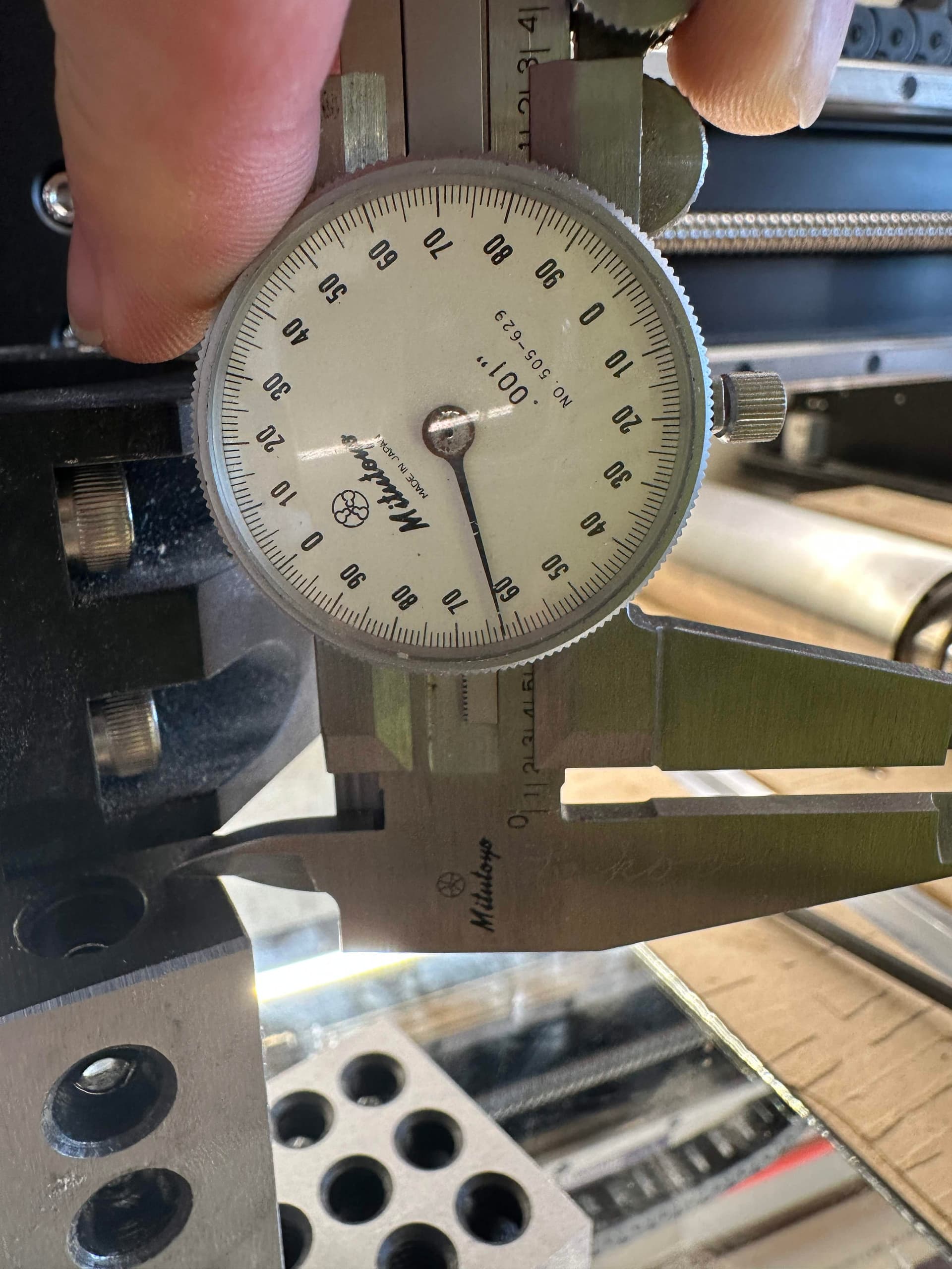
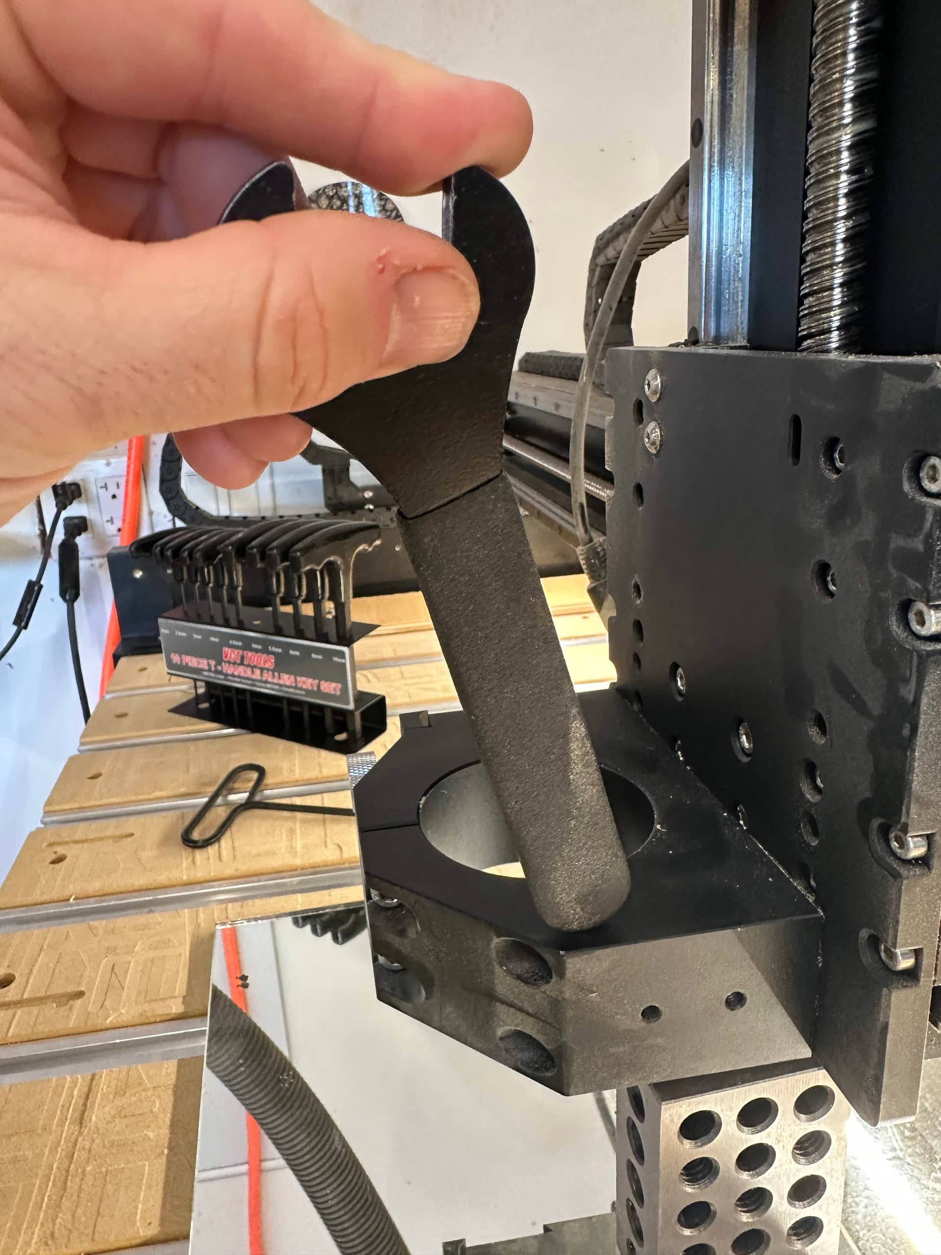
In this case the spindle was leaning forward at the top as my wrench demonstrates.
Now that I know I’m not imagining things and there definitely is a tilt to the spindle, it’s time to actually do some fixing.
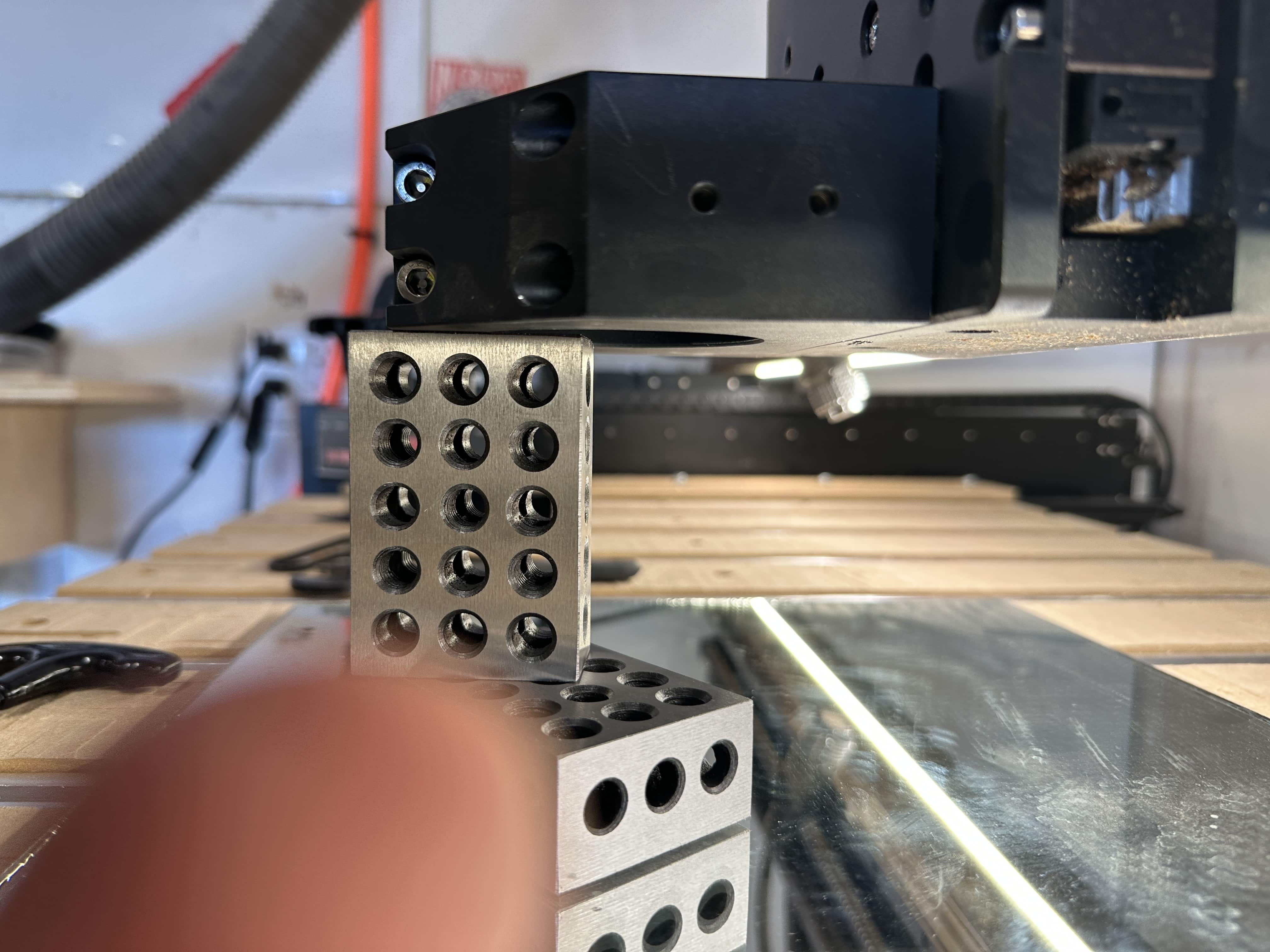
The first step was to very slowly lower the z-axis until the spindle mount was just resting on the 1-2-3 blocks. I put it to the smallest increment and brought it down bit-by-bit until the blocks could no longer move around underneath. If you have it set too high when you move it down, you’ll probably end up cracking the glass and/or getting the z-axis to jump steps.
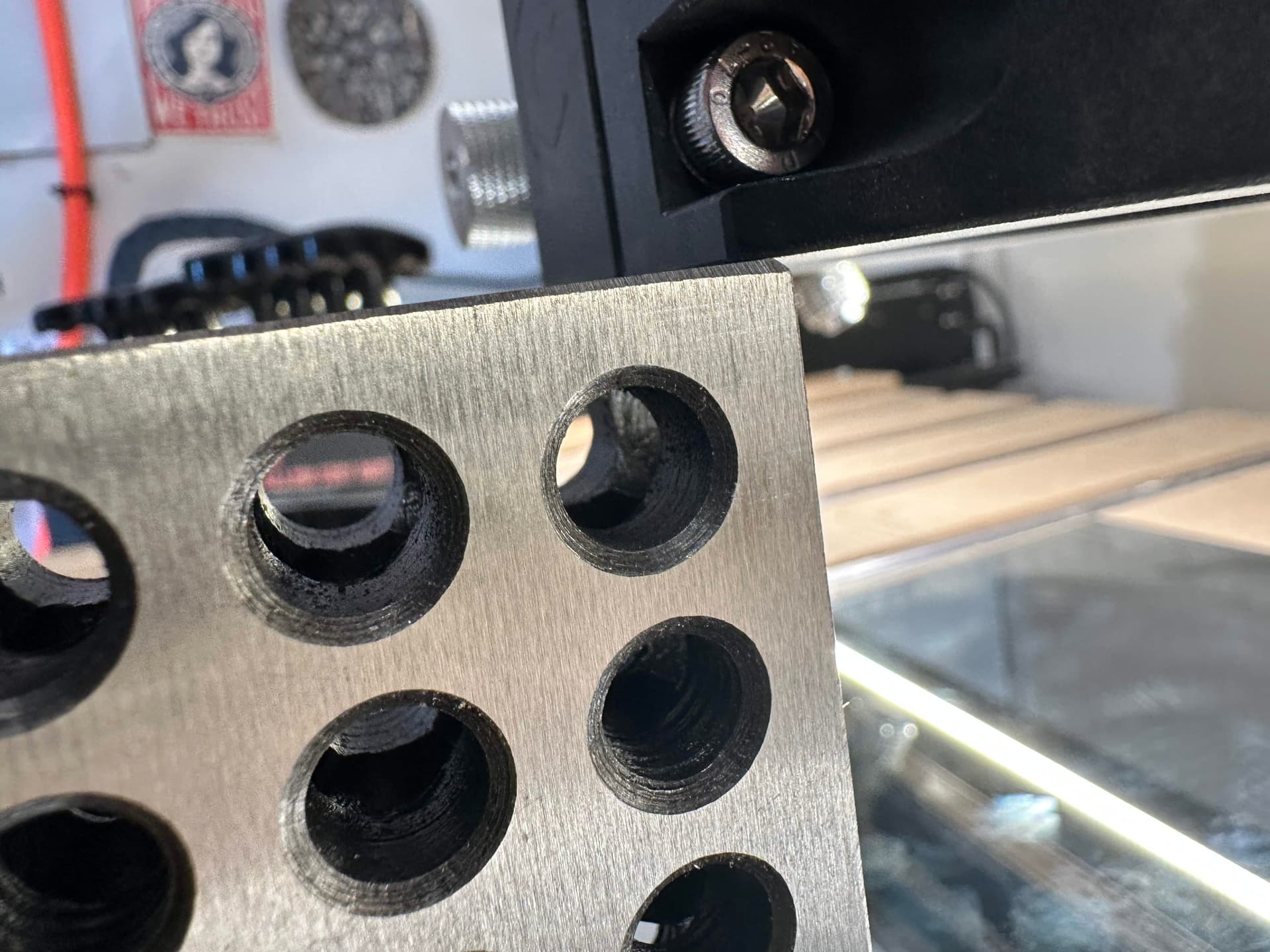
Next I loosened the four screws that connect the spindle mount to the rest of the z-axis.
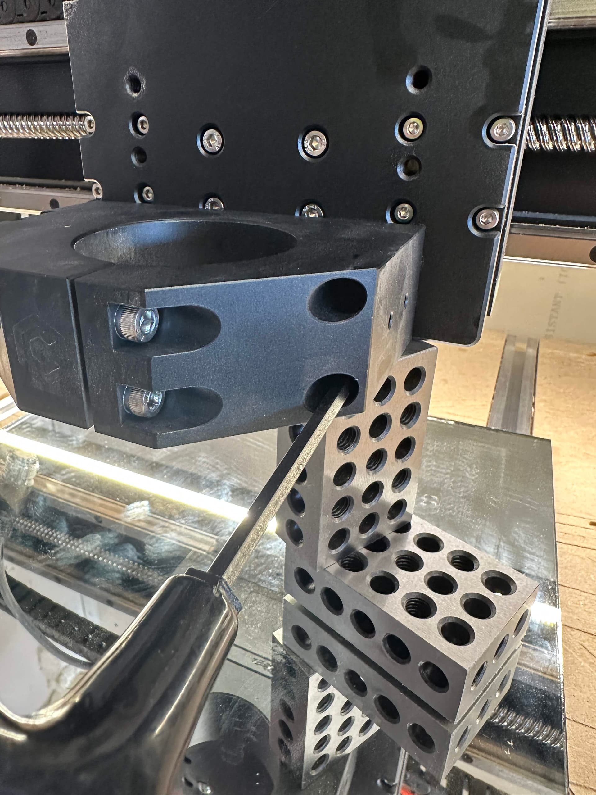
Once all four are loose, the spindle mount has quite a bit of play in it. This is important because even though my goal is to fix a front to back lean, I don’t want to have a side to side lean introduced as I’m tightening things back. Looking along the side, I can see that there’s a gap and it’s pretty clearly wider at the bottom than at the top.
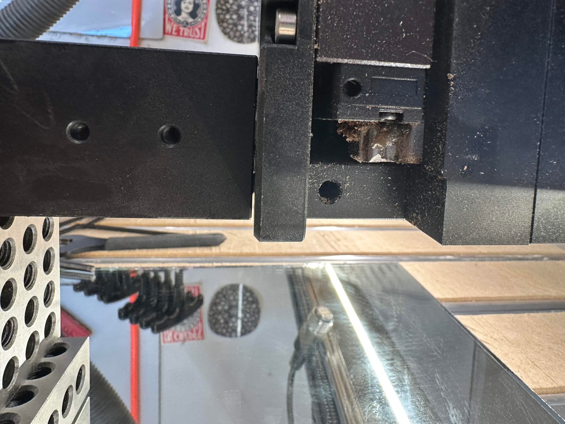
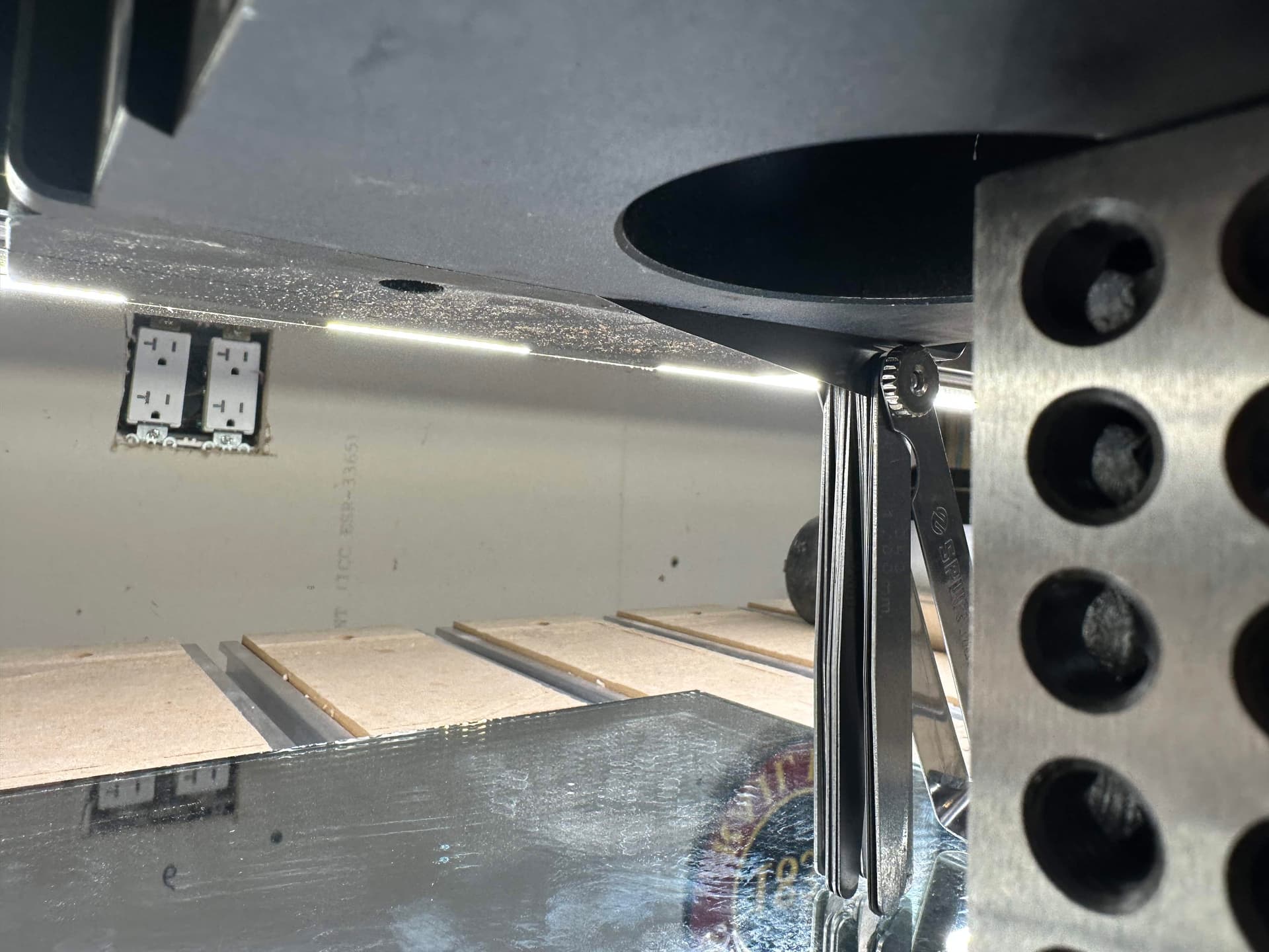
Now it’s time to fix that gap. With things in place, I took the feeler gauge set and tried to see what would fit into the gap. Starting with 0.5mm and working down to 0.3, 0.2, then 0.1 was able to get in but was definitely too lose. So I tried 0.15 which still felt loose, so then I tried 0.18. That seemed good.

After removing it from the set, I slid it lengthwise into the gap at the bottom. All the way in so it was completely hidden in the gap. Keep in mind that the farther into the gap the spacer goes, the more significant the impact will be. I didn’t want it hanging out of the bottom of the mount so I decided to have it fully hidden but you can leave it hanging halfway out if you need or want to.
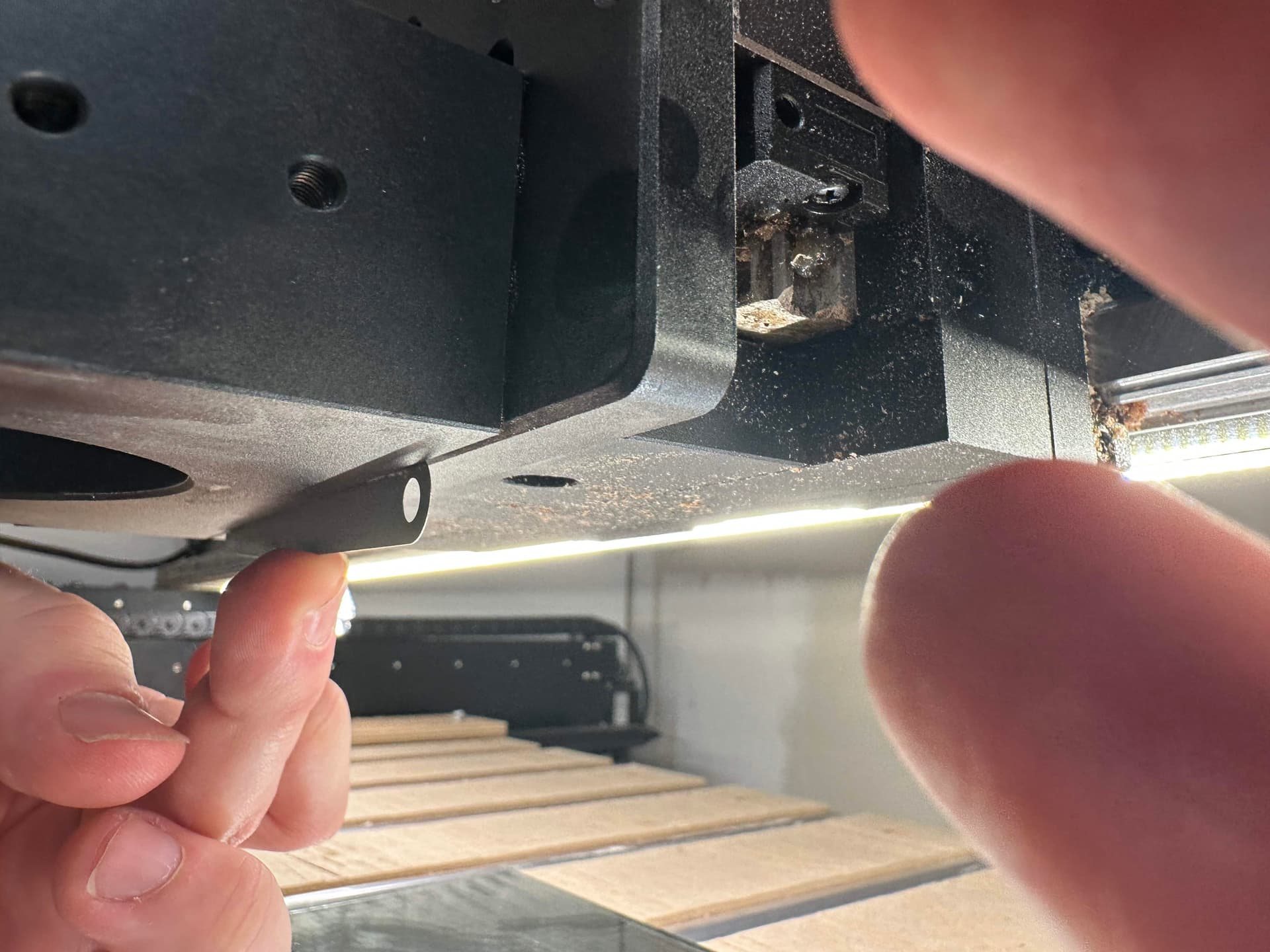
Then tightened the spindle mount screws back up to lock everything in place.
I re-inserted the spindle to the mount and put my surfacing bit in place as well.
Now I got my test board and surfacing job set up. All of the normal steps to starting a project: measure the wood, create the toolpath, zero the head, etc. Initially I left the surfacing default set at a 50% stepover and I had it moving along the x-axis since that was the direction the spindle had been off-axis.
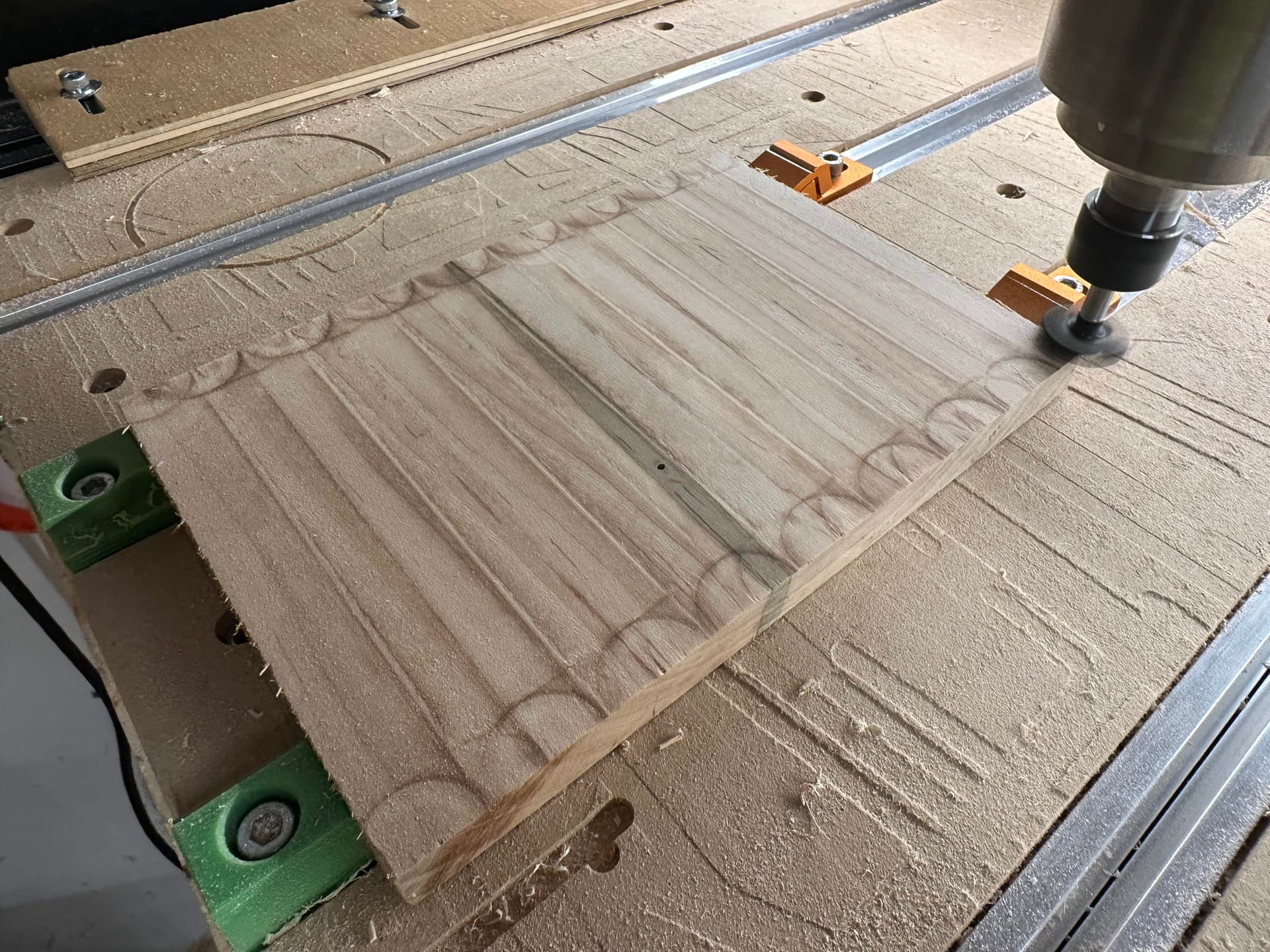
The result was definitely much better than the previous attempt but I could still see burning and feel a bit of a lip between passes. Also, I unintentionally made some decorative notches in my holddown clamps.
At this point, you’ll probably start a bit of a cycle. Based on the result of the surfacing test, check to see if you can figure out which way it might still need to be adjusted. In my case, I felt like it might have been adjusted too far and needed to be tilted down just a little. You’ll need to follow the steps until you get things the way you are happy with them:
- Determine which direction the adjustment is needed
- Re-align the spindle over the 1-2-3 blocks and glass
- Lower in place so the blocks are supporting the mount
- Loosen the spindle mount screws
- Remove the spacer that is currently in place
- Add a spacer that adjusts in the direction you want: thicker spacer will lift the front of the mount up, thinner spacer will bring it down
- Re-tighten everything
- Re-set your z-zero and re-run your flattening job
- Go back to step 1 and repeat until you’re happy
For me, this meant that I went from a 0.18" to a 0.13" spacer. This time it felt like I went a little too far in the other direction.
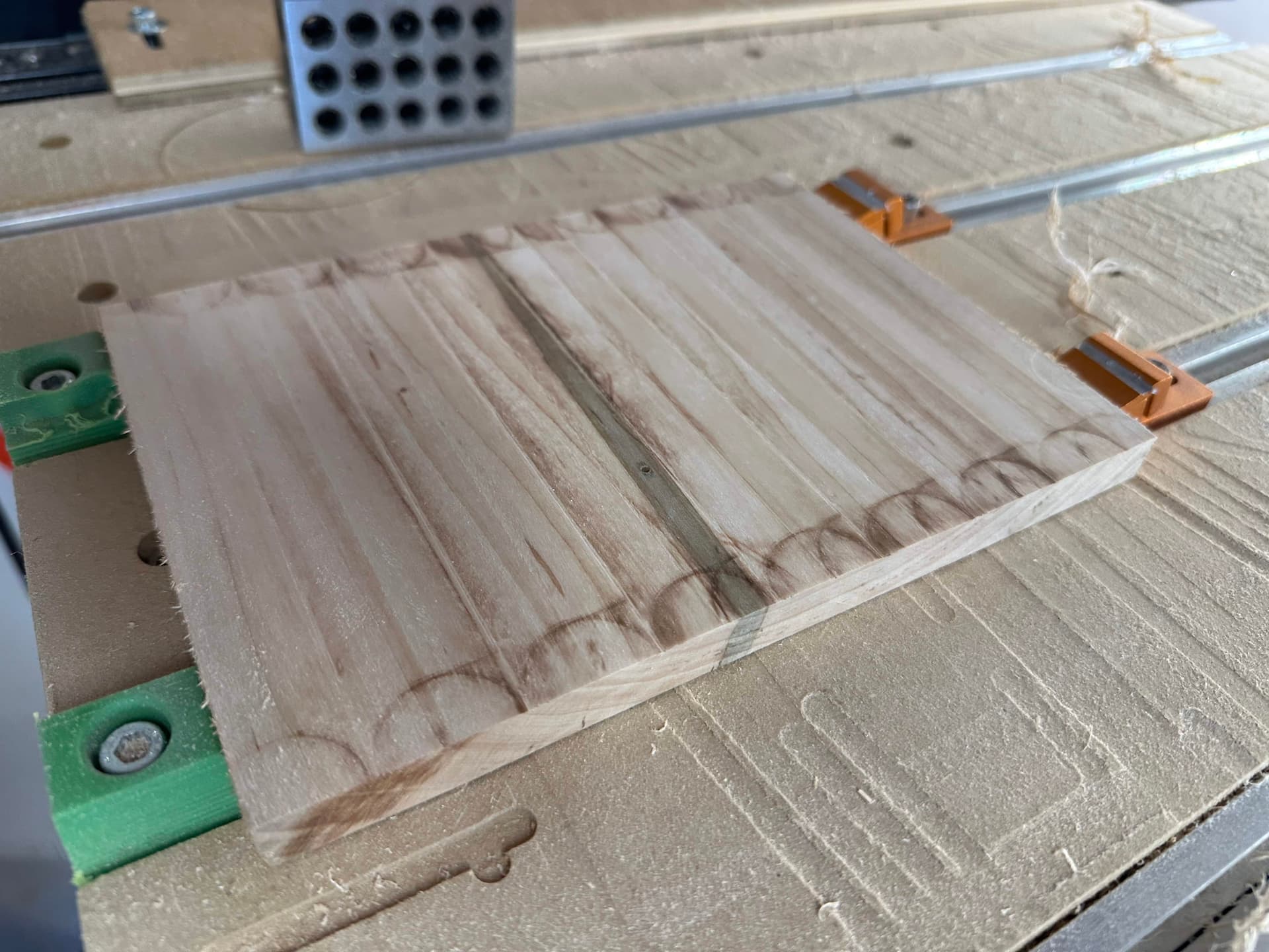
So I tried a 0.15" spacer which was definitely the best so far, but still not perfect.
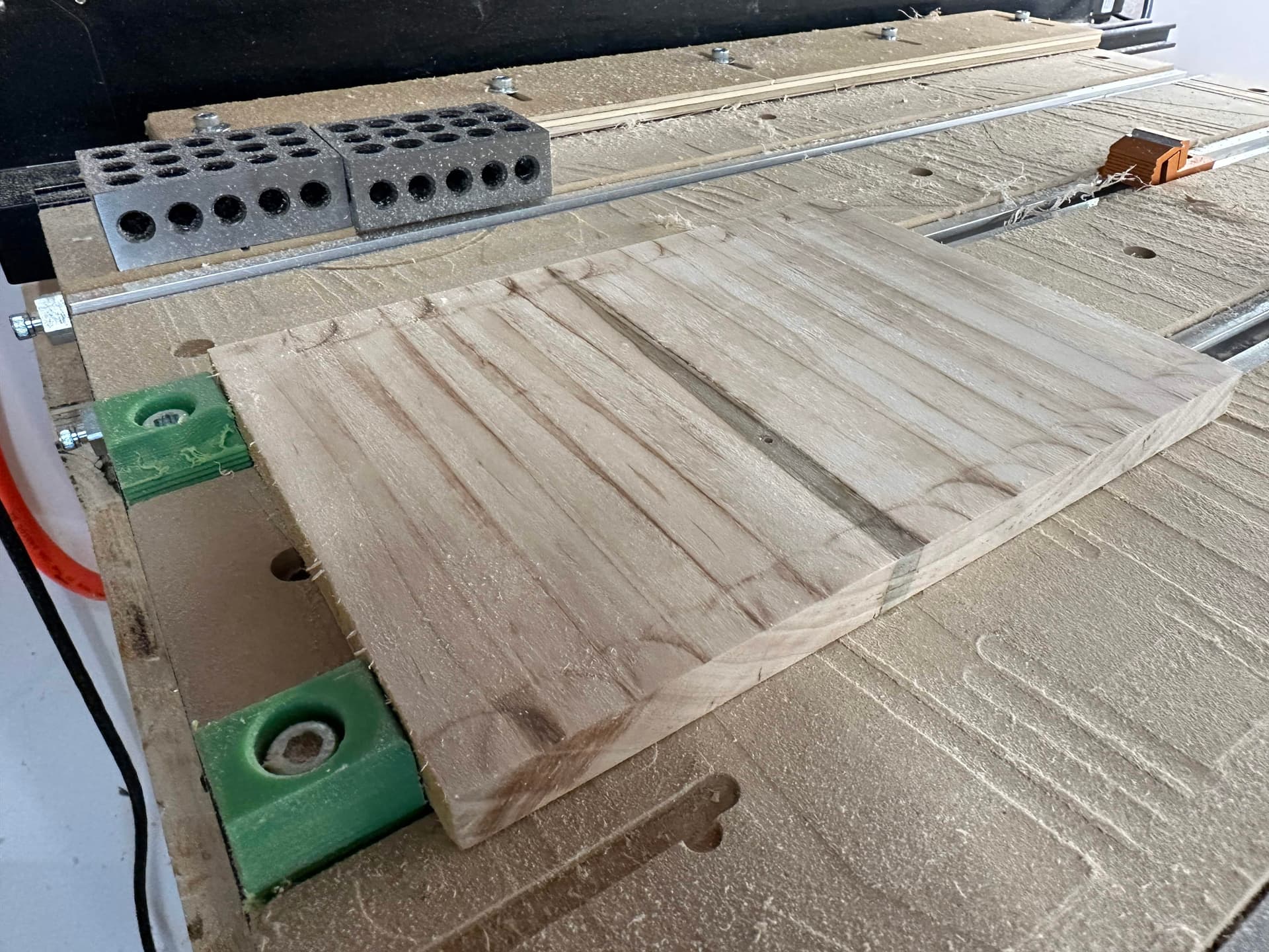
I would have loved to try a 0.16" spacer but the set I have didn’t have anything between 0.15 and 0.18. I thought about stacking two together, but decided that it was good enough. I also changed my job from a 50% stepover to a 100% stepover because I realized that the overlap would mean that there was less clarity about which direction the problem was really in.
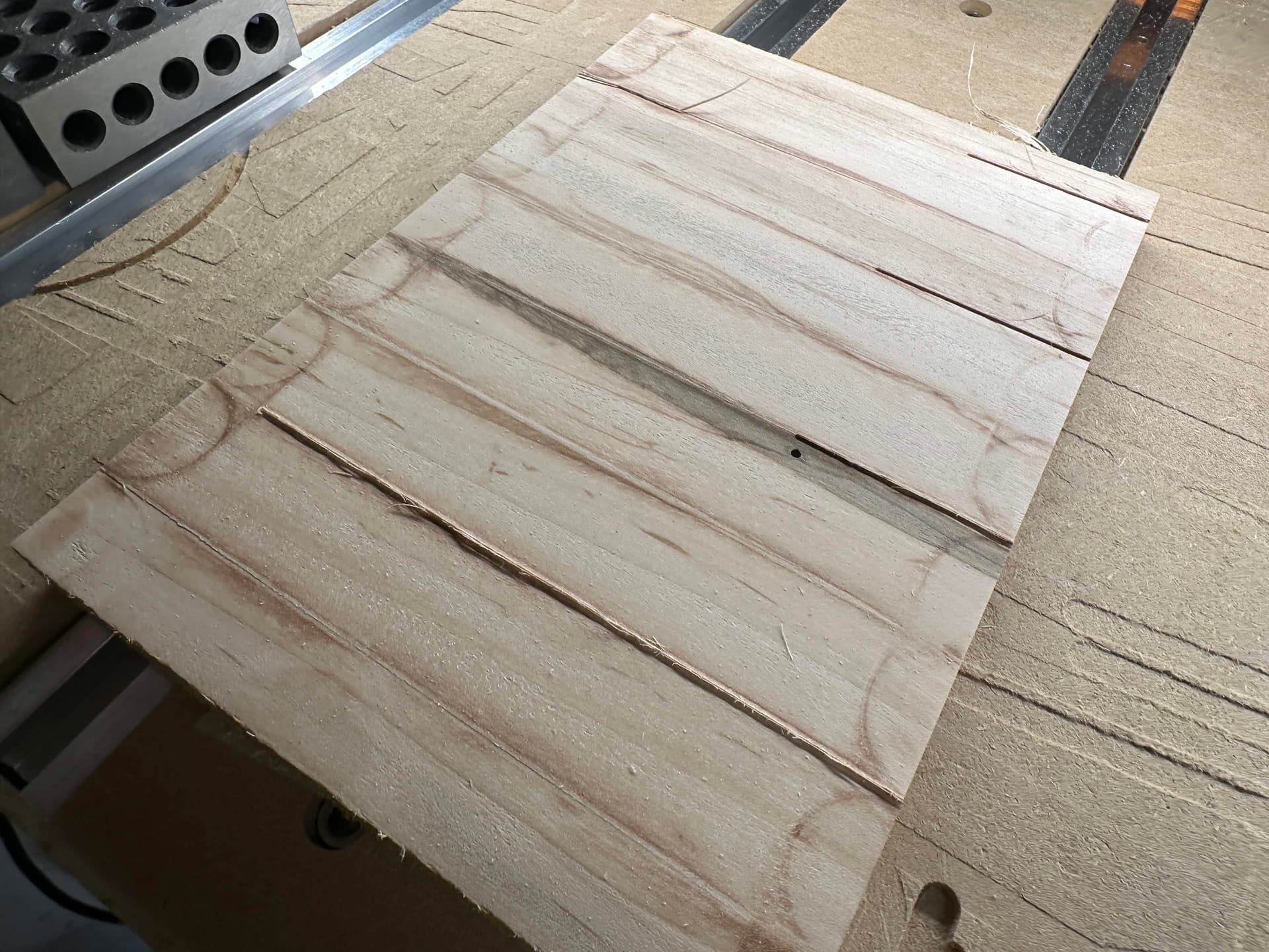
There was still some burning, but it was pretty minimal and actually seemed to be happening on both sides of the pathway, so I decided to stop there.
As a test, I updated the surfacing toolpath to go 90 degrees for the angle. This way I could see if there was any visible tilt in the side-to-side direction.
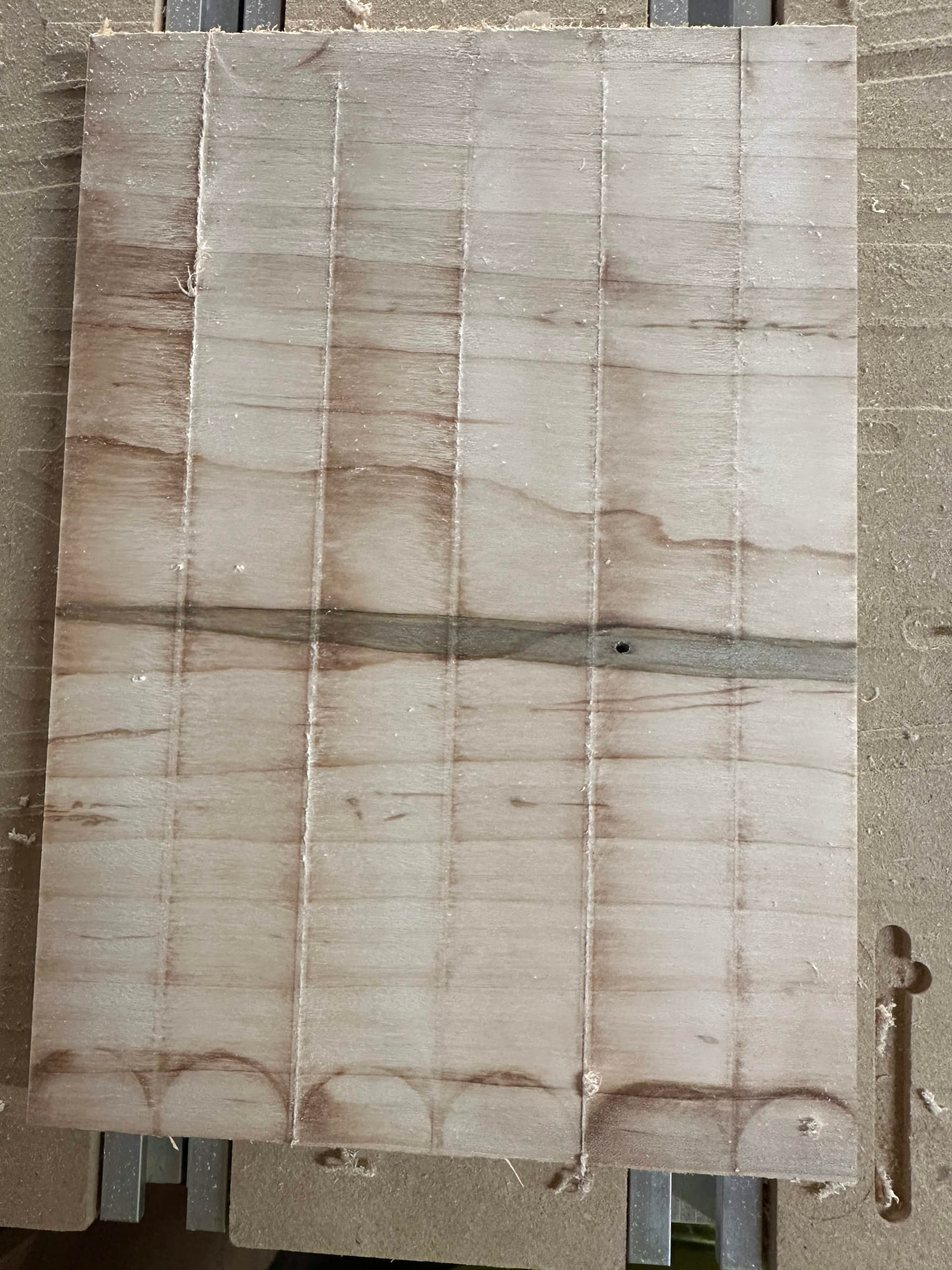
Based on the results, I couldn’t see a clear angle that looked worse than the others so I decided this would work. I switched from clamps to double-sided tape because my board was getting thin so there could be some movement as the head is going over from some small amount of play in the tape or in the unevenness of the spoil board or something.
So that was my whole process. It would be great to have some kind of built-in capability to adjust the tramming, but this worked and wasn’t too hard. Yes it’s tedious, but I doubt that any process for doing this would be much easier or quicker anyway. I haven’t had a chance to try it out on anything since doing this so I’ll post a follow-up once I’ve given it a try this weekend.
Hope this helps!