I just wanted to check with people and see if my out of square 3XXL is a typical amount to resolve or if something is off. What is the recommended way to resolve this? Shims?
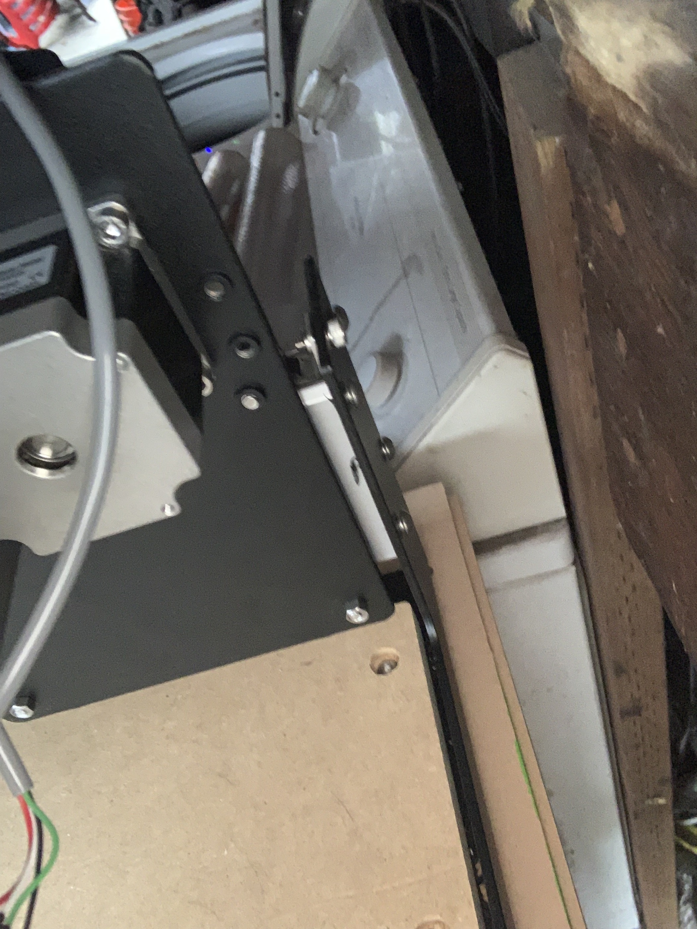
What are we looking at here?
1 Like
The community has a bit at: https://wiki.shapeoko.com/index.php/Calibration_and_Squaring_the_Machine#Squaring_the_Machine
(please don’t use the ratchet straps though).
There’s a more specific set of instructions w/ some guidelines you can get if you mail in to support@carbide3d.com (EDIT: which is just a rehashing of what’s on the wiki w/ some reassuring text).
Left rear Y axis meeting the end of the rail. Front right is similar.
Add an additional washer behind each (top/bottom) front wheel on the other side of the gantry, and see how it looks then.
Oh and yeah, I find that roughly the same as mine when I started. Washers behind wheels is a great/fast way to square these.
NOTICE… I had to edit this to change the washer location, because I wasn’t clear what side I was looking at. Add the washers kitty-corner to your gap, both top and bottom wheel.
1 Like
There’s a more specific set of instructions w/ some guidelines you can get if you mail in to support@carbide3d.com
Sounds like content that should be on docs.carbide3d.com! ![]()
1 Like
Just to clarify, on an X my gaps are top left and bottom right. You’re saying add washers on bottom left and top right?
Pull the gantry all the way forward, to the very front of the machine. You’re going to have a gap either on the left or right hand side. Add washers to the rear of the opposite side of the gap, one each behind both the top and bottom wheel. So you’ll already have washers in those locations, you’re adding one more.
Note that this is easy for me to visualize because I’ve done it. Once you’ve done it you’ll smack your forehead and hopefully explain this to the next guy squaring his machine. 
It comes up rarely enough, that we would rather help folks who have the problem at need, than worry potential customers who will never see the issue. As I edited in, it’s just a rehashing of what’s on the wiki with some reassuring text.
The whole documentation thing is a balancing act — we’re trying hard to find the right balance, and we don’t always succeed, but this at least is intentional.
1 Like
I have the exact same issue. How did you resolve it,?
What wheels are you talking about,?
The v-wheels on the left and right of the gantry. There are four each side.
1 Like
I recommend measuring opposing corner to corner and check the base frame first to see if the base is square or racked.
2 Likes
Well that is a good point in that we need to measure to make sure we’re out of square, not just rely on a gap.
But follow me on this…
If the extrusions are tight to the front and rear base assemblies, then the only way to correct a racked assembly would be to file or shim the extrusions. One is a PITA, the other can devolve into tail chasing.
We can ignore all of that entirely, if we just check square between the gantry extrusion, and the left or right extrusions.
And the easiest way to do that, is to clamp a 1-1/2" thick piece of MDF (double-up two 3/4" pieces) to the front of the gantry extrusion, so it extends the plane down to the waste board. Now you can now measure with a trusted square between this piece of MDF, and the left or right extrusion.
If you’re out of square, shim the appropriate v-wheels of the gantry with extra washers until you’re square.
On my machine, once I did this, my gap was also gone.
You guys are going to have to trust me, my method isolates the only variable that actually matters and fixes it to a degree that the filers and shimmers probably cannot achieve in less than tens of hours.
The real problem with my method is the variability in washer thicknesses. To find the optimum washers, I simply went to my hardware store with my caliper and started measuring washers to use for shimming. They have very thin mylar washers as well that I could have resorted to, but there was no need as two stainless washers on the thinner side fixed me right up.
And I’m not trying to sound disagreeable or anything, just trying to point-out a super-easy way for new users to get their machines insanely square and move on to step #2: Making stuff.
3 Likes
If you ever find the motivation to do a sketch of your method, it would be very cool. I re-read some of these sentences 3 times and am still not 100% sure to get it right
I went for the shimming option, it turned out near perfect, but I did spend an awful lot of time folding aluminium foil, tightening everything, realizing it is still a tiny but too much/not enough, starting over, etc…so I’m tempted to give your method a try next time I have to square my machine.
2 Likes
Phil, this is great info! I’ve been manually “pulling and holding” my gantry into square position (simply to remedy the same gap) before turning the power on. Once the steppers engage it holds things in place nicely. HOWEVER, I think I’ll have to give the washer thing a try very soon. Would be great to not have to rely on my old brain to remember to pull things together prior to cutting each time. Thanks for the great tips!
I’m sorry, like I said for me it makes perfect sense because I’ve done it.
Try this…
Looking at the SO3 from the top, the gantry has left and right plates (the plates with the wheels and motors). Each plate has four v-wheels, two in front (upper/lower), two in back (upper/lower).
(1) Pull the gantry all the way forward and identify the side with the gap (left or right).
(2) On the OPPOSITE side, add an additional washer behind both the top and bottom wheels at the REAR of the plate.
Once you do it, sketch it out and post it. Or make a video. ![]()
3 Likes
So in the form of a horrible doodle on a post-it note, you start from this:
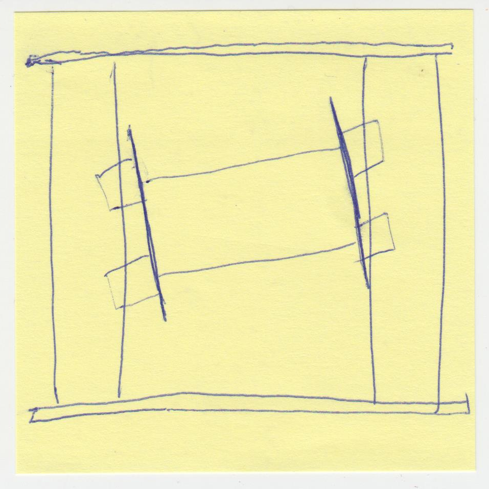
and then end up with this ?
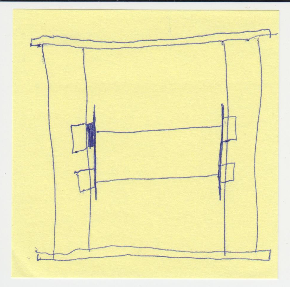
Would you not want/need to add a washer on the right front side wheels too?
2 Likes
Hi guys . I had a similar situation and measuring the framework unit is square corner to corner. My thoughts were the y travel is relative to the drive motors and cogs in the belt. When powered up i brought the y travel close to the front and measured the distance on left and right rails. I found i was out by 1/8 inch. I loosened 1 y belt off and moved gantry 1 belt cog to make both sides equal. Now the y is square relative to both the drive motors since pitch is the same on both sides. Hope this makes a little sense. Maybe I’m missing something. Please correct me as I’m new here to.
You’ve got it perfect, and I love your sketch.
You likely only need to add a set of washers in the corner you’ve highlighted unless your machine is way out of whack.
For people giving this a shot, I’d suggest adding one set of additional washers and checking for square again. If you hit it perfectly, great. If you’re a tiny bit under or over, measure the thickness of the washers you’ve added and find another set of washers a tiny bit thinner or thicker and try those.
I think I said above that I went to the hardware store and measured a bunch of stainless washers until I found a range that I could use for shimming. With very little trial and error I was able to get my machine spot-on.
My hardware store sells metric and non-metric and stainless and zinc and mylar washers that would all work and give me a huge range of adjustment.
2 Likes