I have the Shapeoko 3 XXL with HDZ and 65 mm spindle. I am using Carbide Create Pro v8 build 836.
I imported a 3d STL of a 2 sided snack tray that is round with a floral pattern. I understand how to import both sides of the image separately. The problem I am having is that I cannot use the alignment tools to edit the image nor can I select the image to create an offset to cut it out after it is carved,
I have watched Kevin Barnett’s video on flip machining but he did not use a 3d STL file to setup the project.
Looking for any information or guidance on how to carve and cut out a two sided 3d STL file in Carbide Create Pro v8.
Thank you for responding Will.
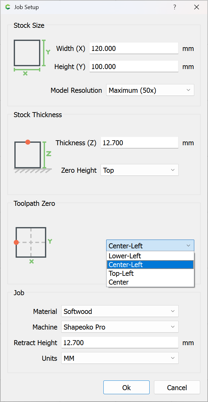
If I am understanding correctly you import the image top in one rectangle and the image bottom separately in the other rectangle. Is this correct?
My bigger question is how do I cut the image out since I cannot edit it to create an offset or add tabs directly to the profile of the image?
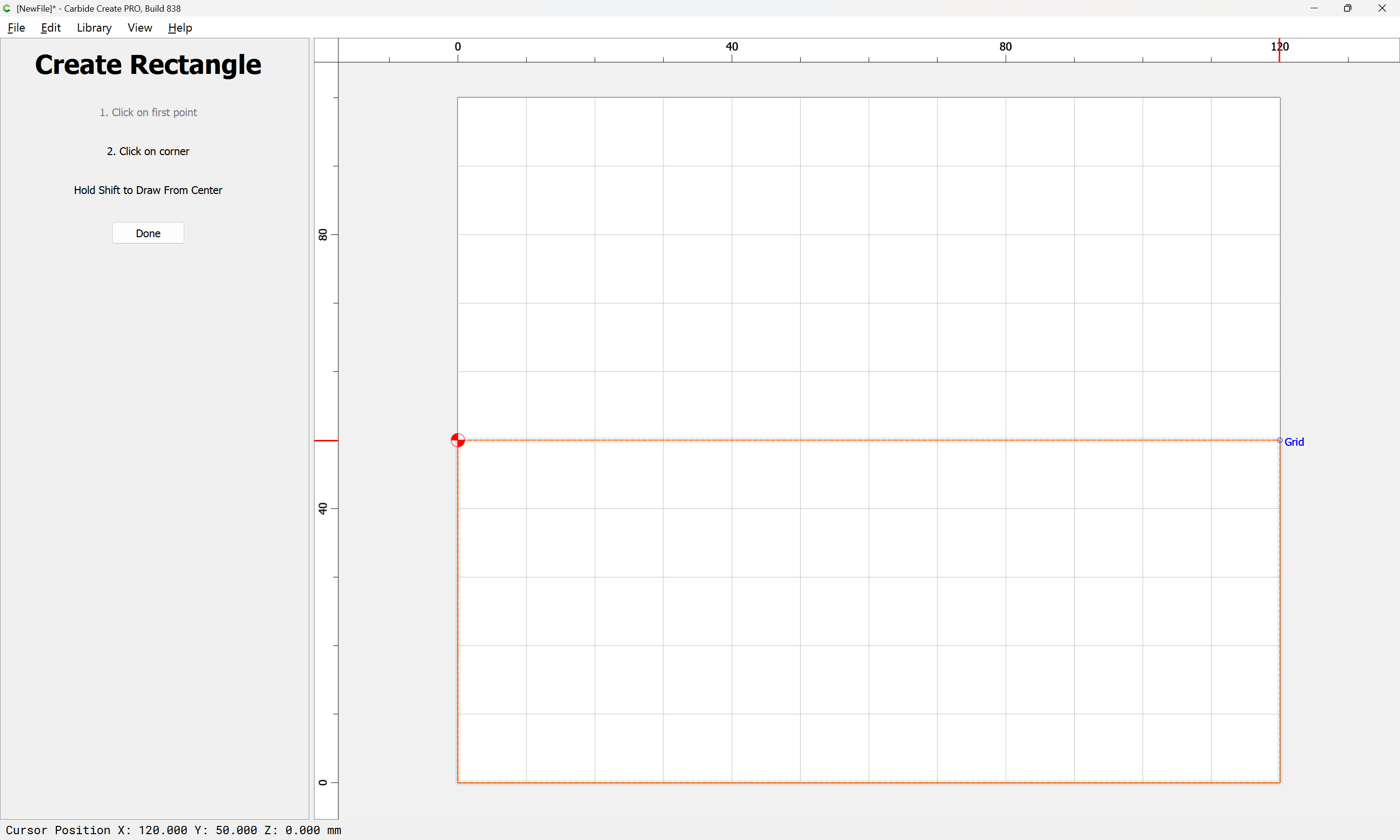
If you right-click on the 3D component, you can select Create Outline Vectors
You might have to play around with the Height Threshold value, but it usually works at 0.0 to get the outermost outline.
I believe I did try that option to Create Outline Vectors but it did not show the actual outline vector so I presumed it did not work. Is it supposed to show an outline vector like an offset vector?
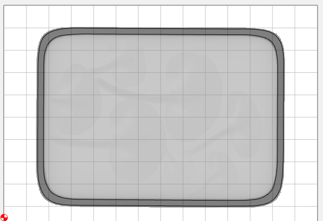
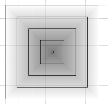
It’s more of a horizontal section through the solid component. Here’s one I just did. I had to increase the Height for the section, or it would only get the outside vector
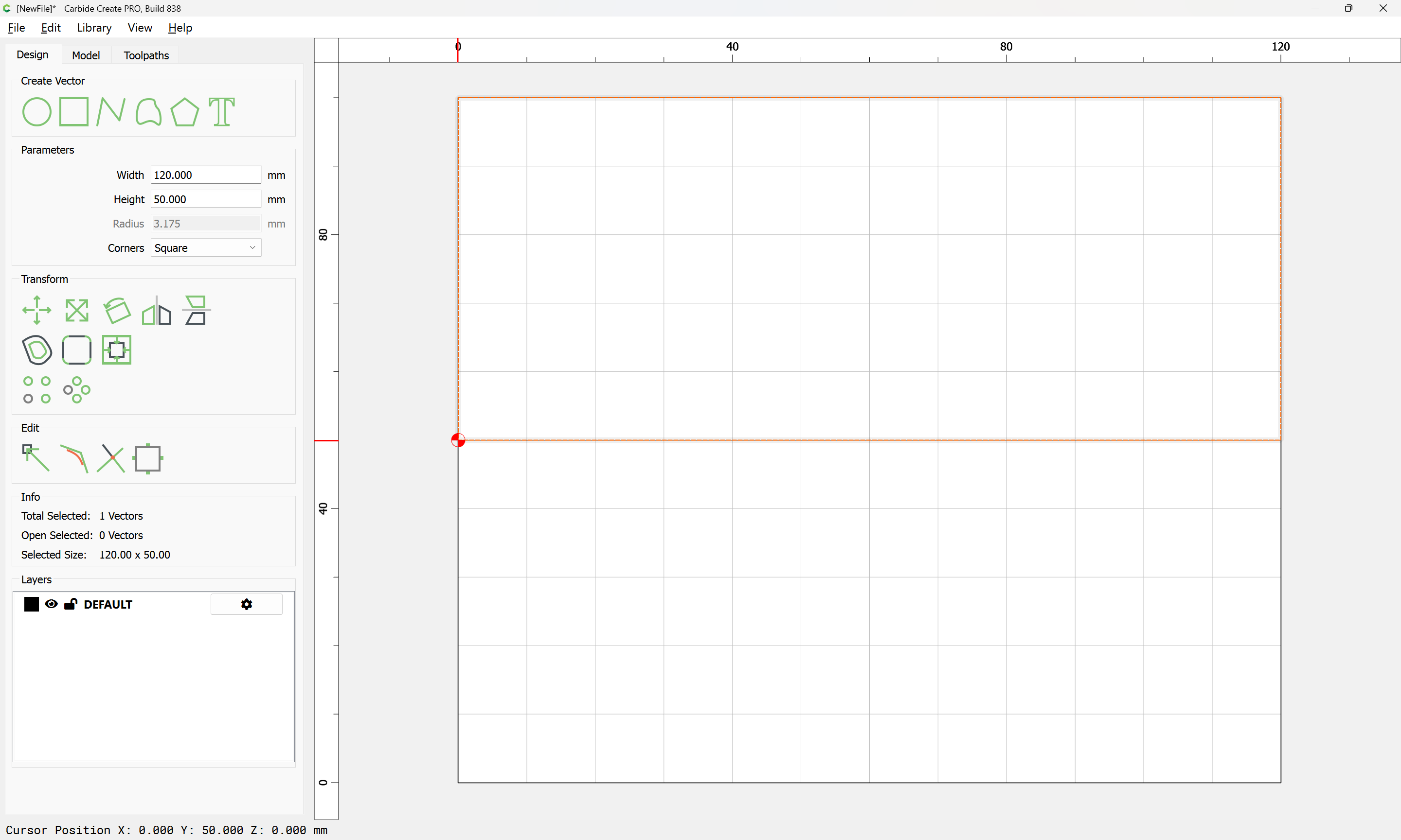
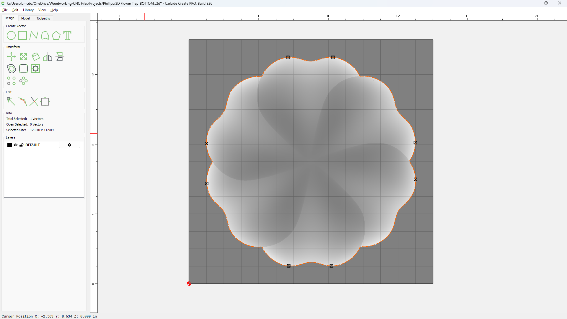
This is the bottom side of the 3d tray I am working with and I added the outline vector with a height of 0.0 to cut the outer profile after the carve is completed.
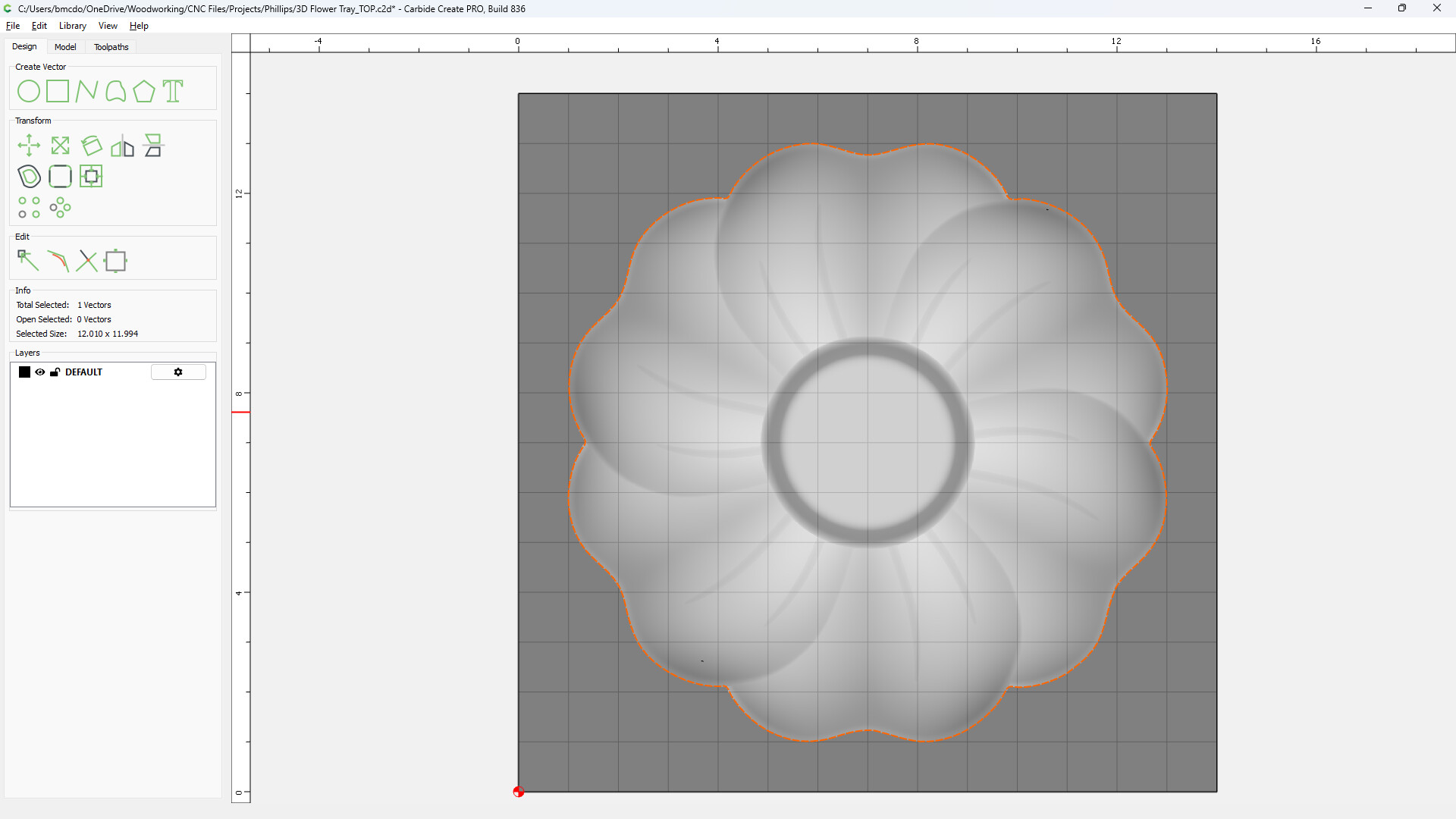
That sounds correct. If you have the top shape as STL, it will import as Top & Bottom views with the outer edges / silhouettes projected down the base level. So either one traced at 0.0 will give you the outermost boundary, or parting line. You can see this when you “Show 3D”