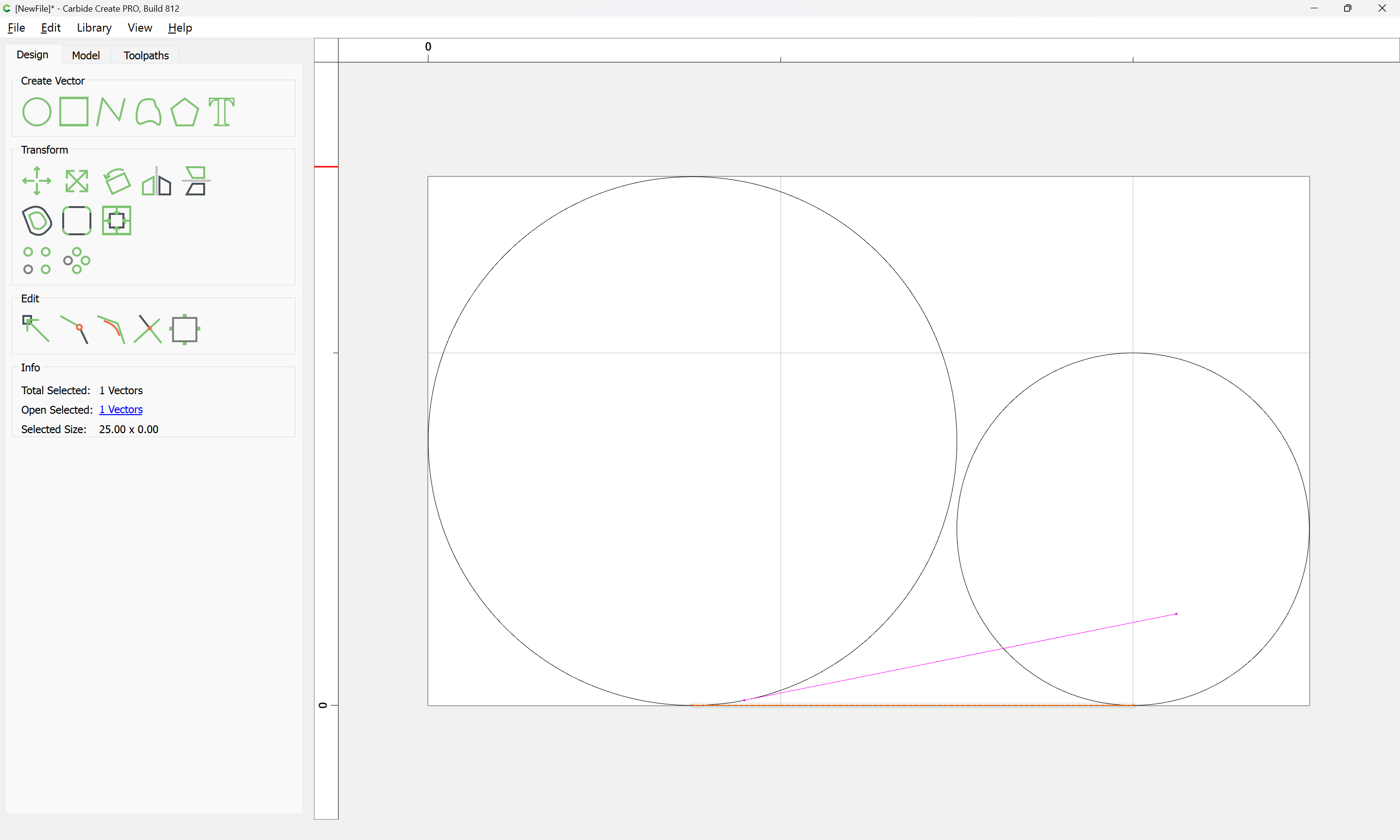
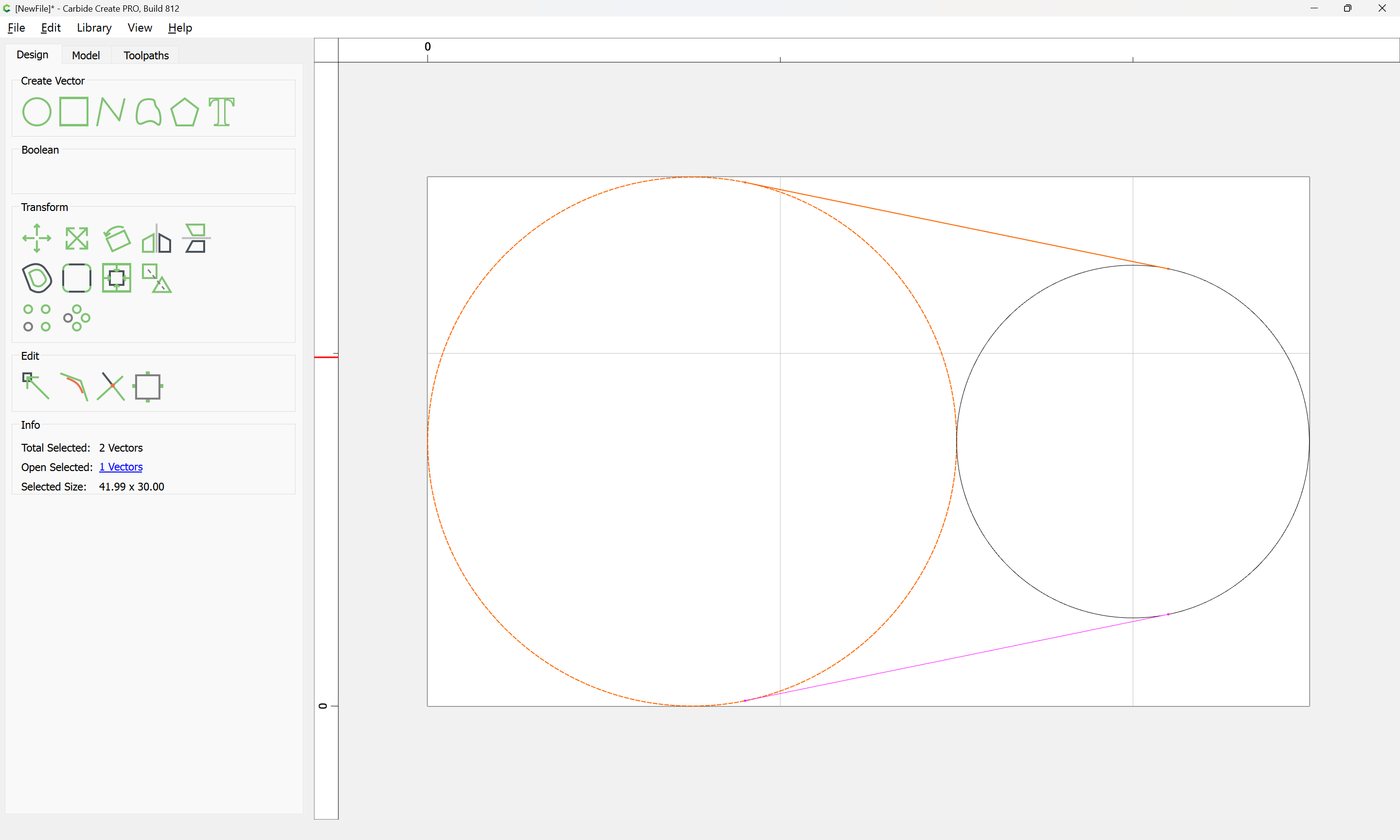
Alternately, the new Measurement tool in Carbide Create makes this a bit easier:
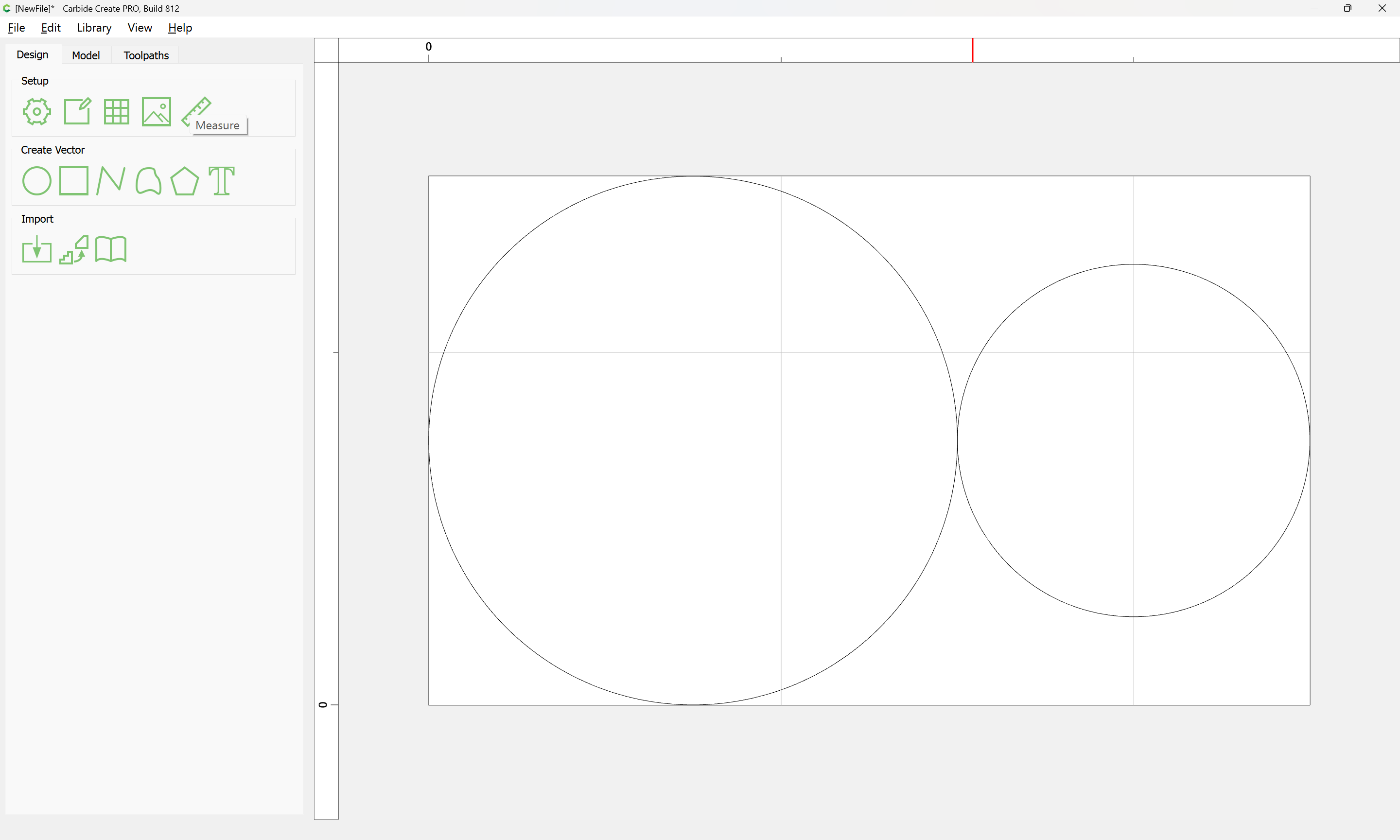
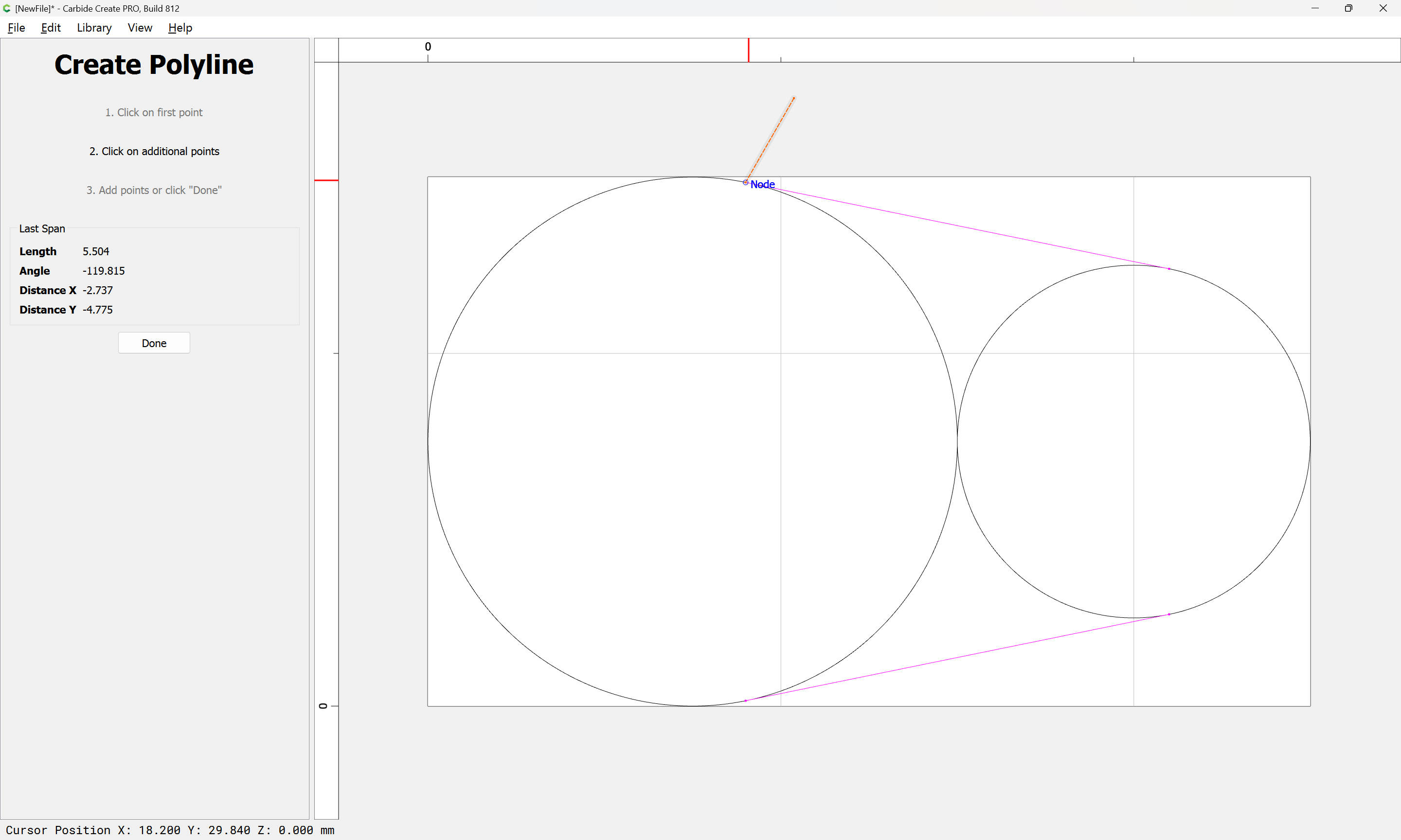
Measure from Node-to-Node:

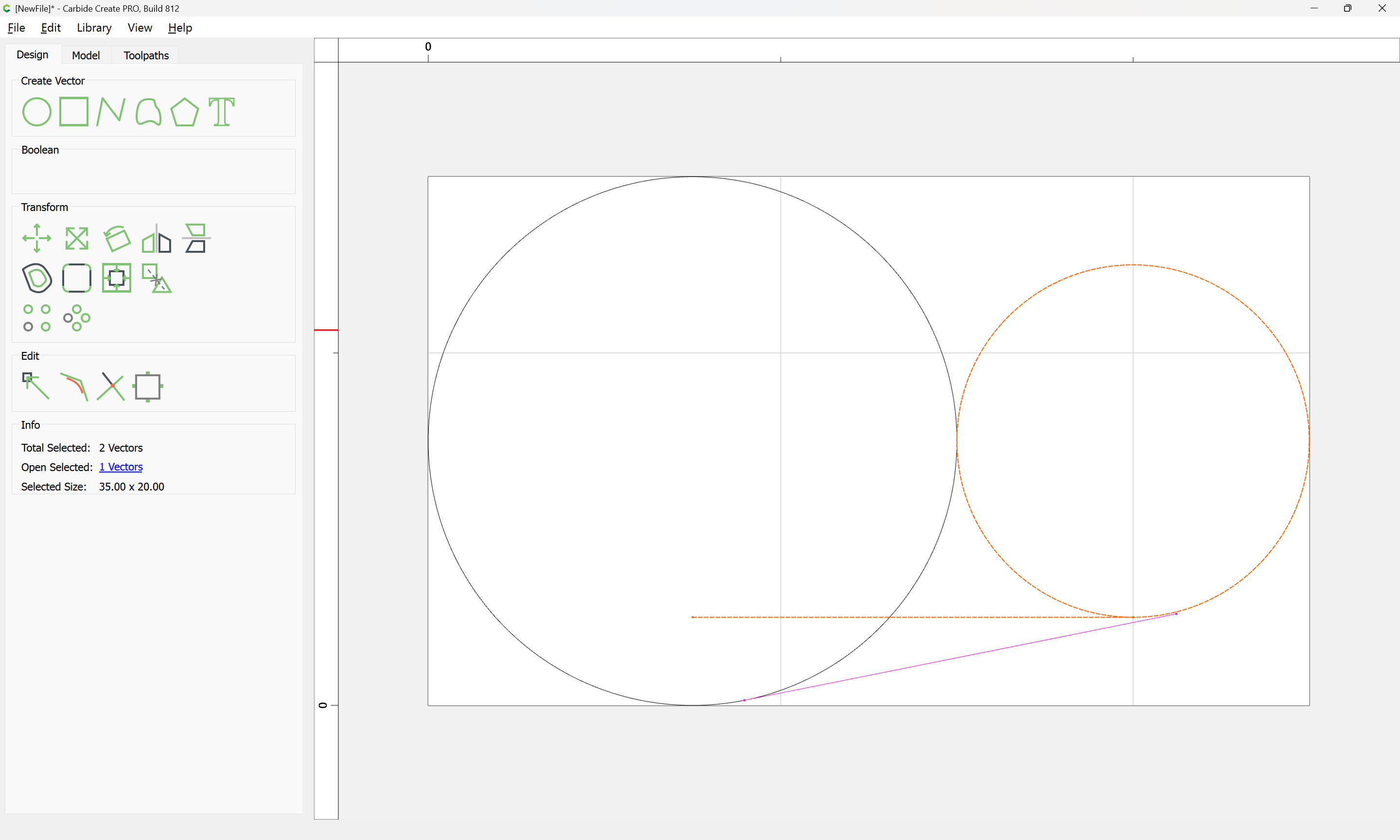
Note the angle (11.311) and draw a line:
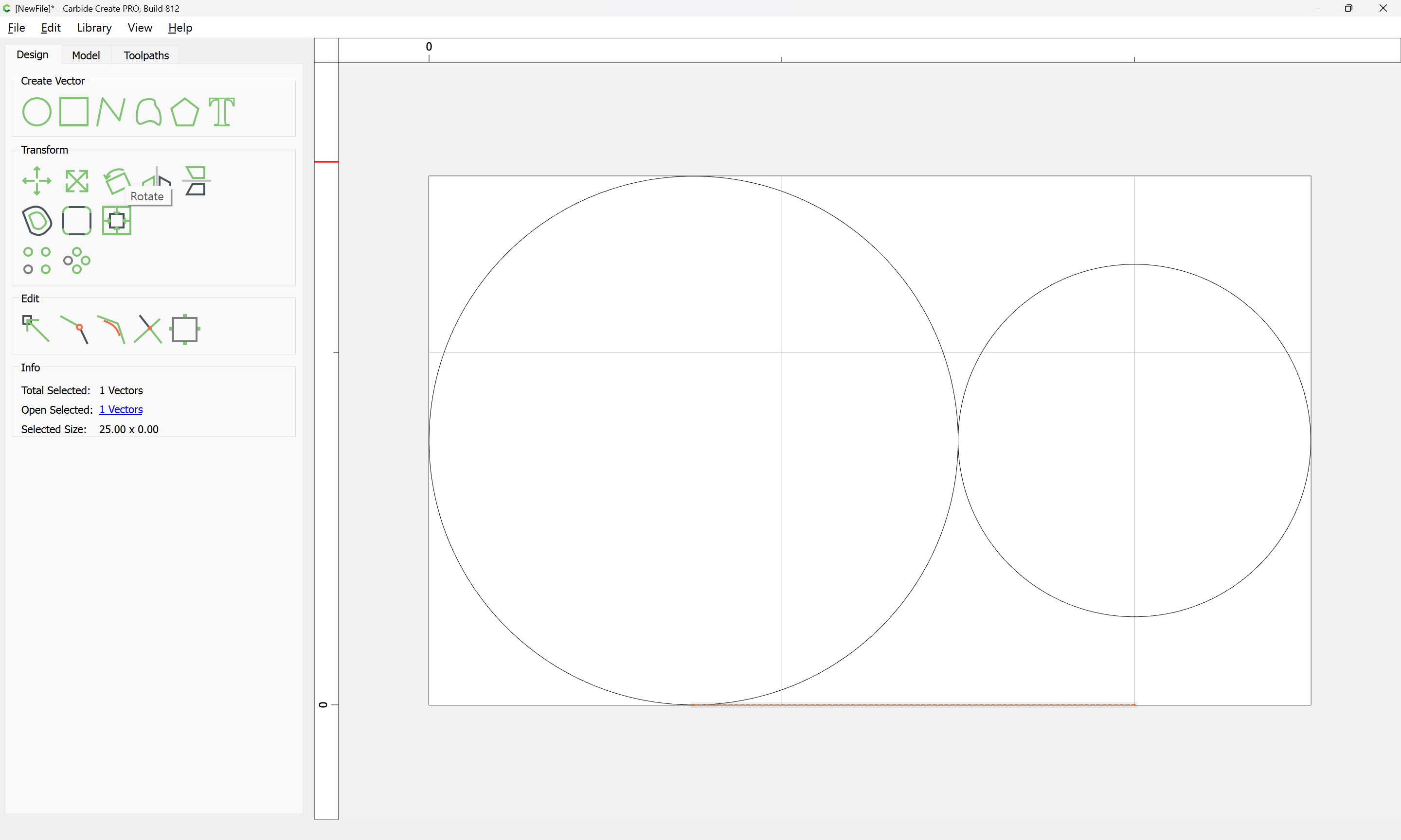
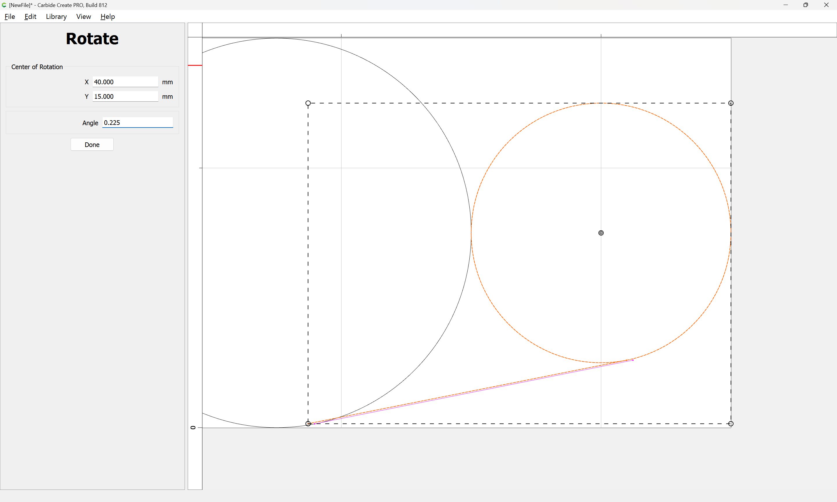
Select the larger circle and the line:
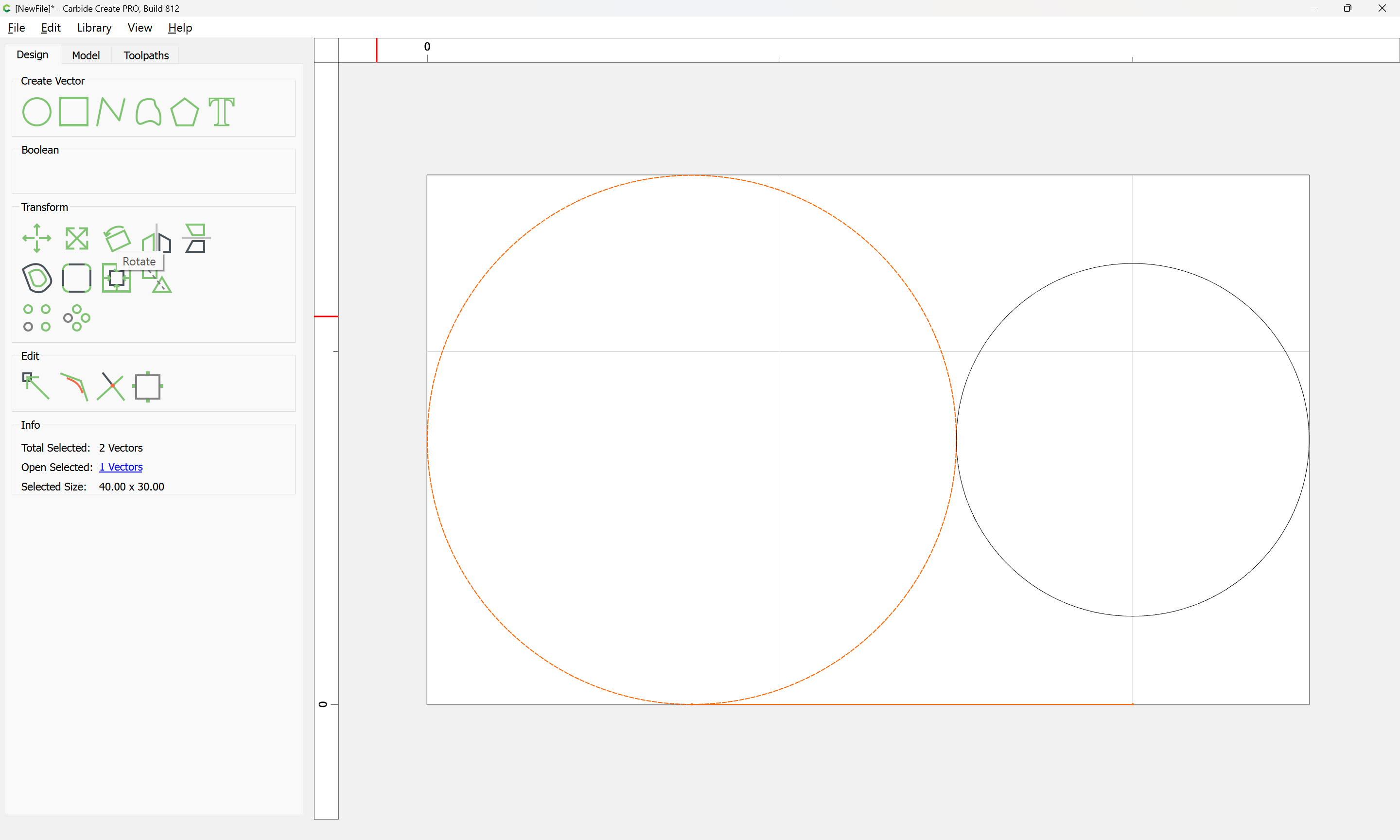
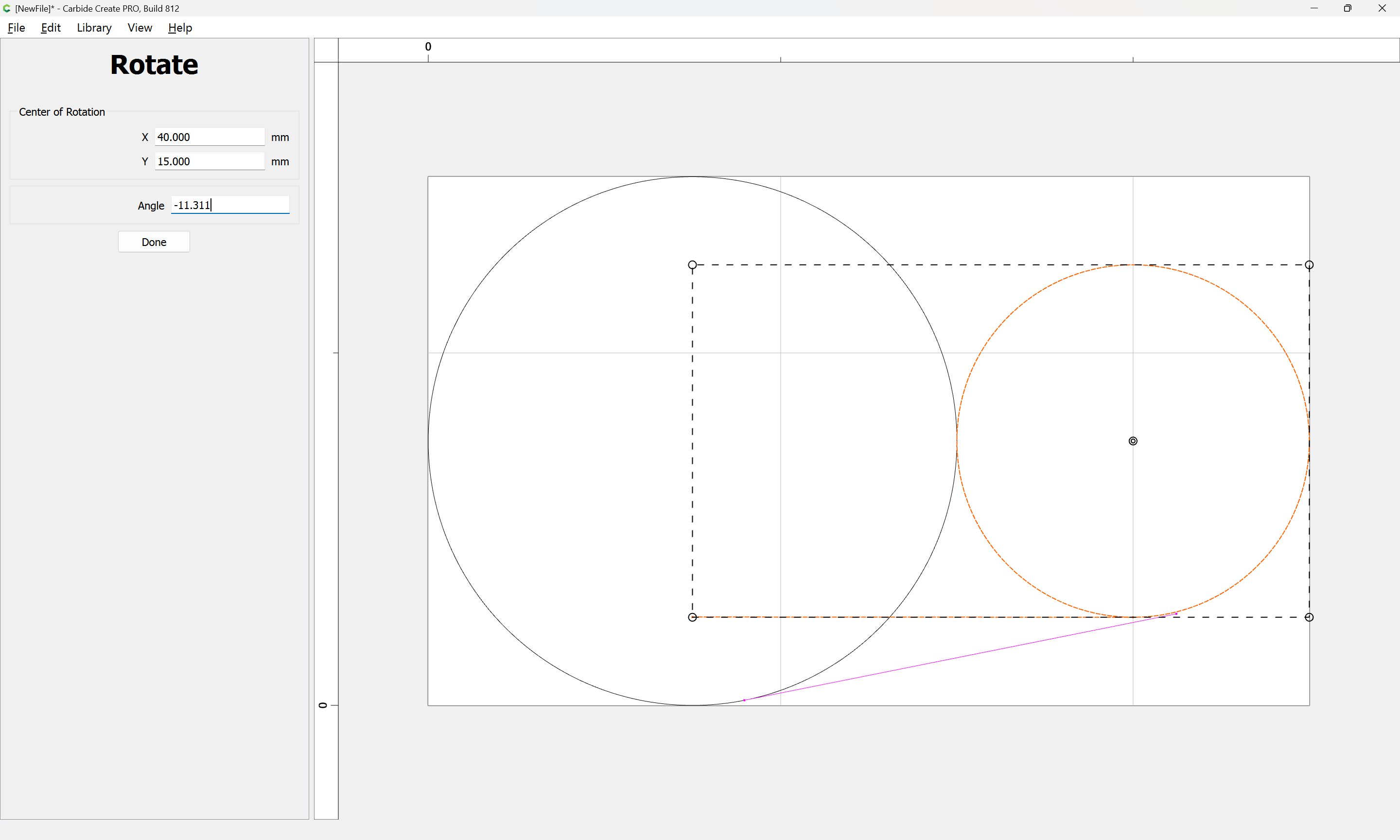
Rotate

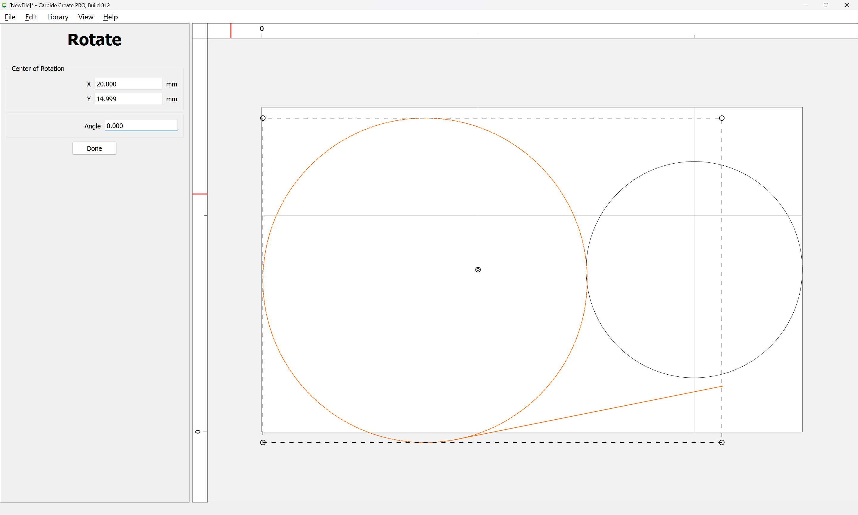
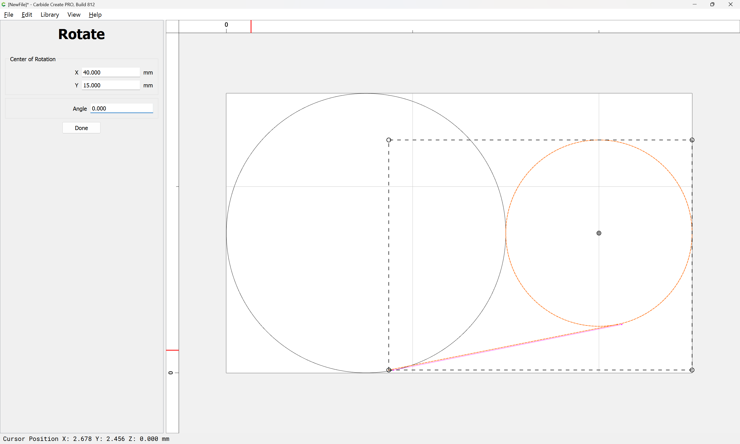
Done
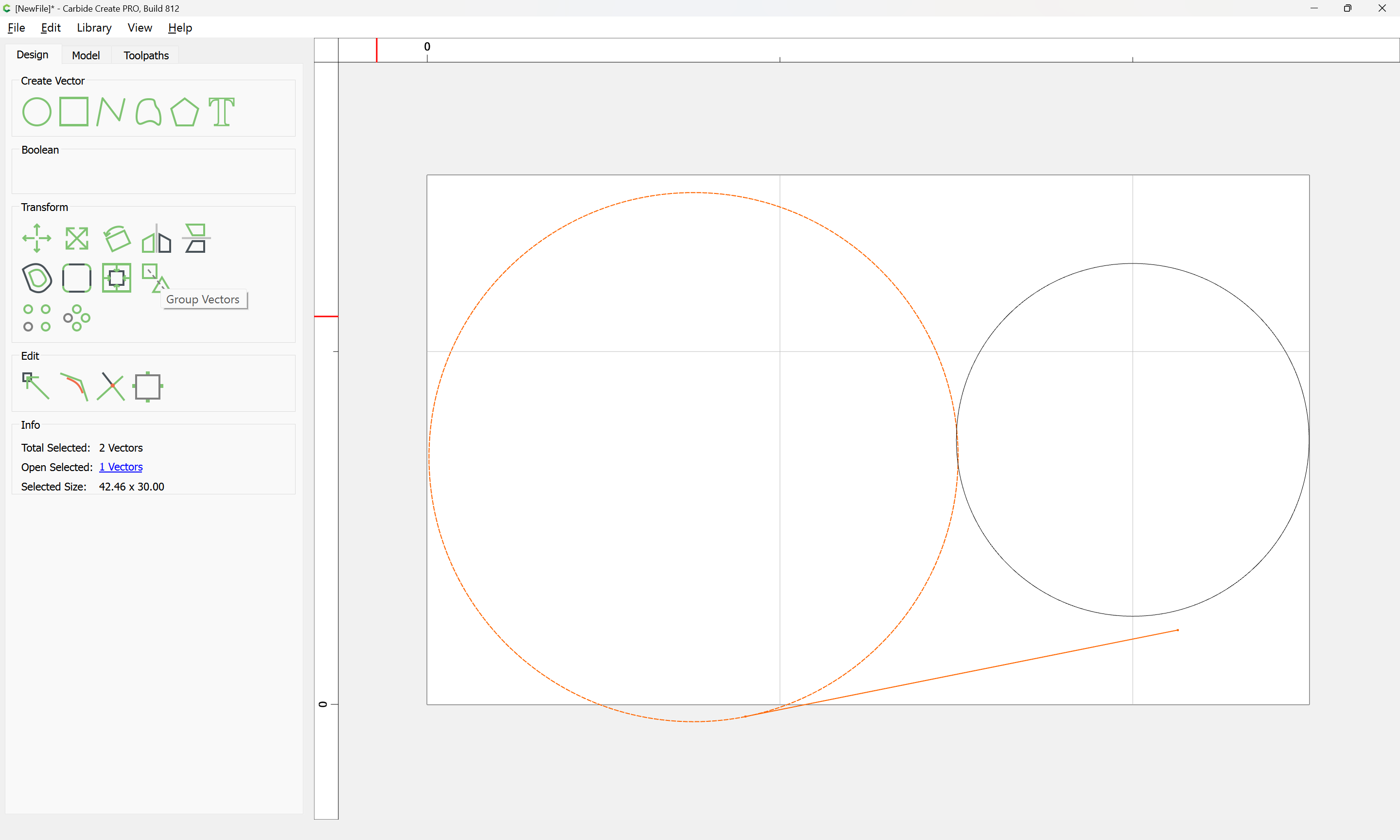
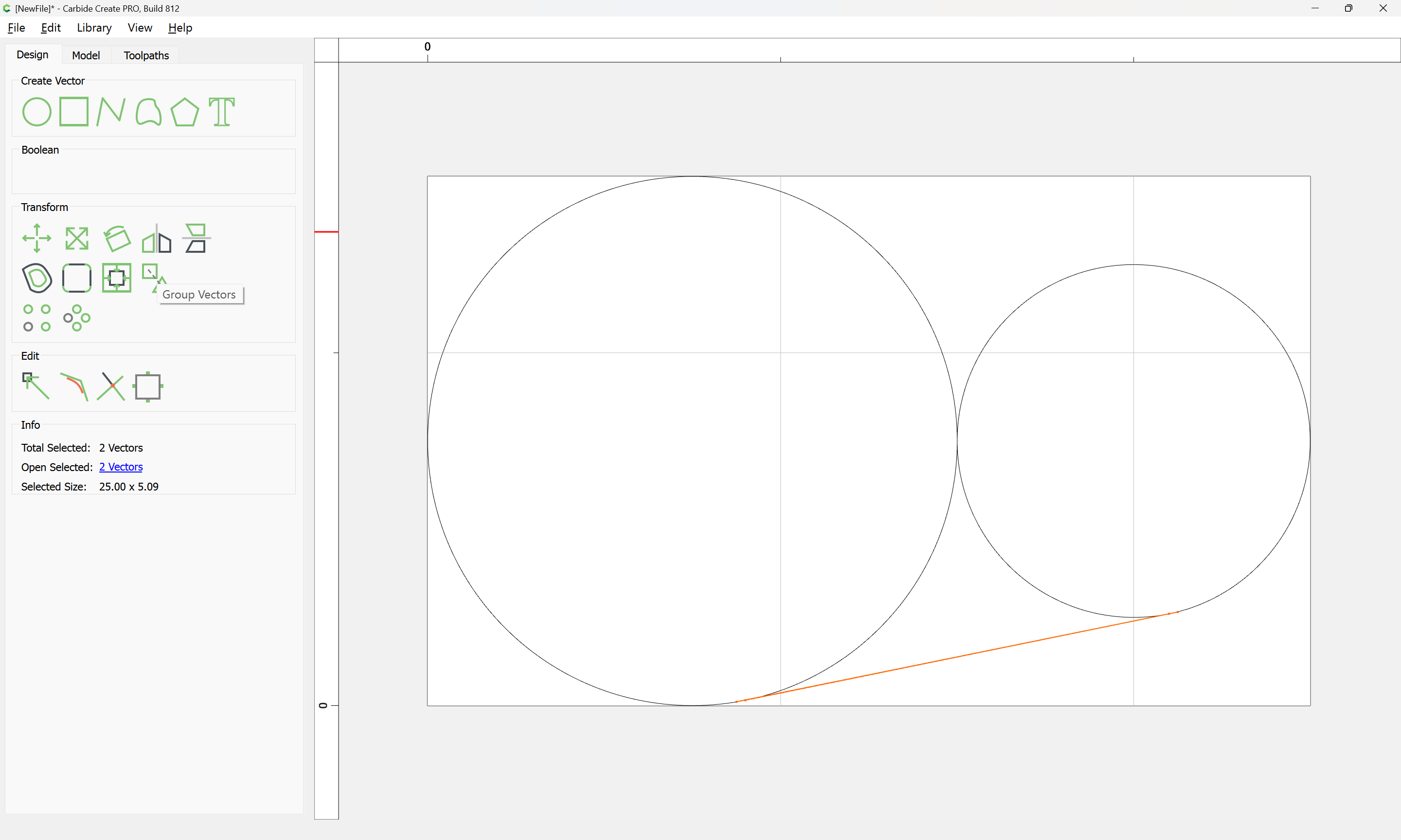
Group

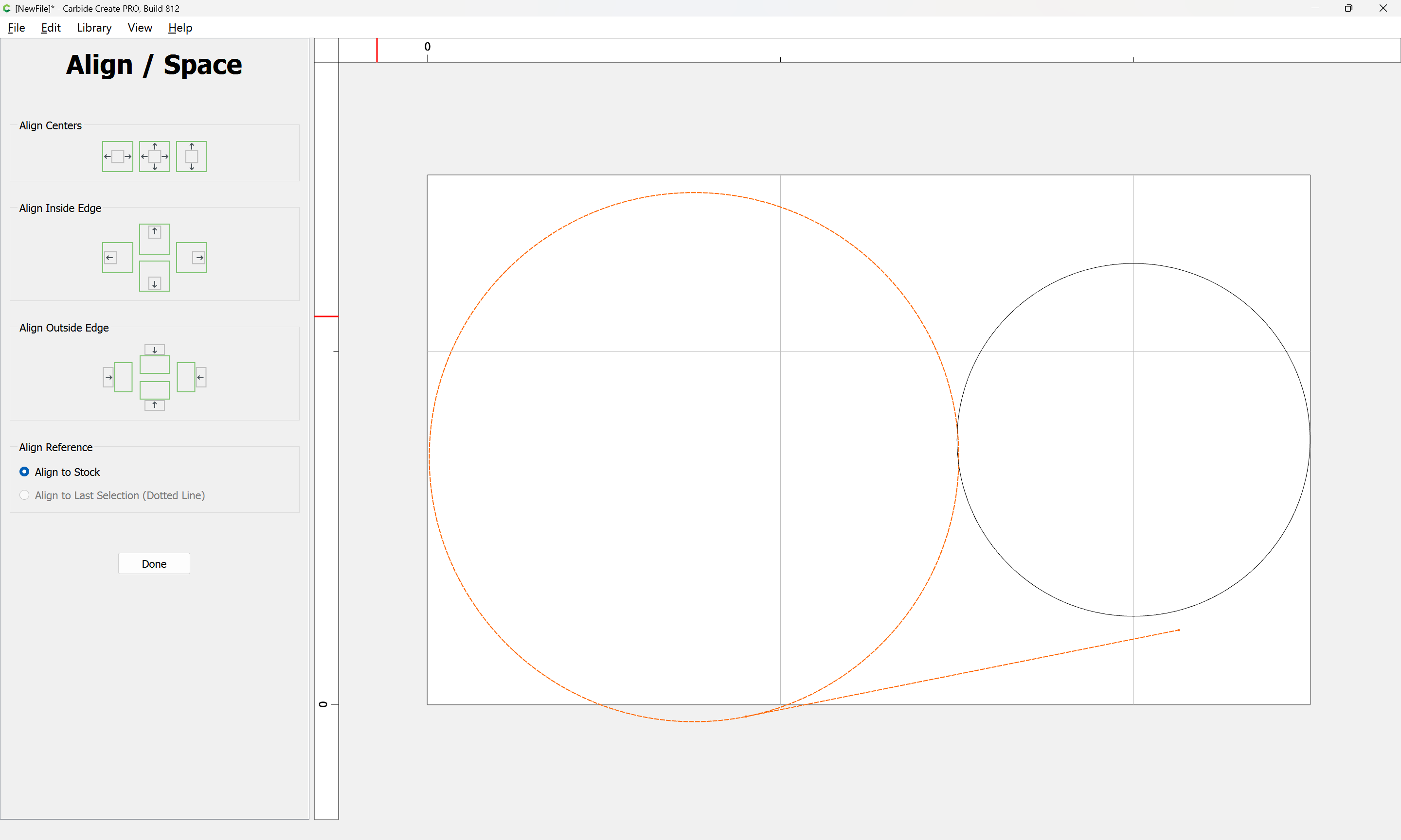
Align Vectors
(twice)
Note that due to the different sizes of the circles things do not line up as one might expect.
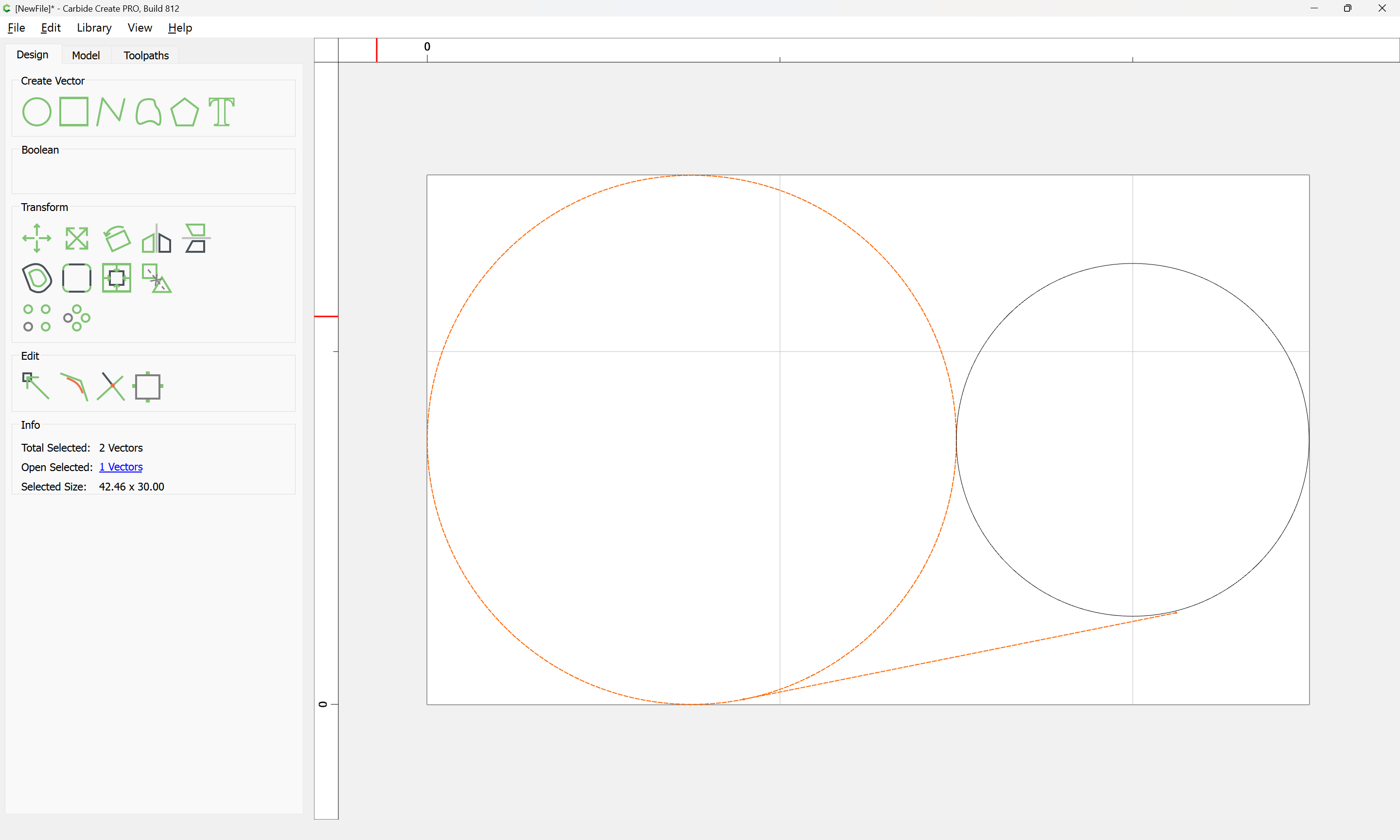
Repeat this for the other circle — probably easiest to align the smaller circle at the bottom:

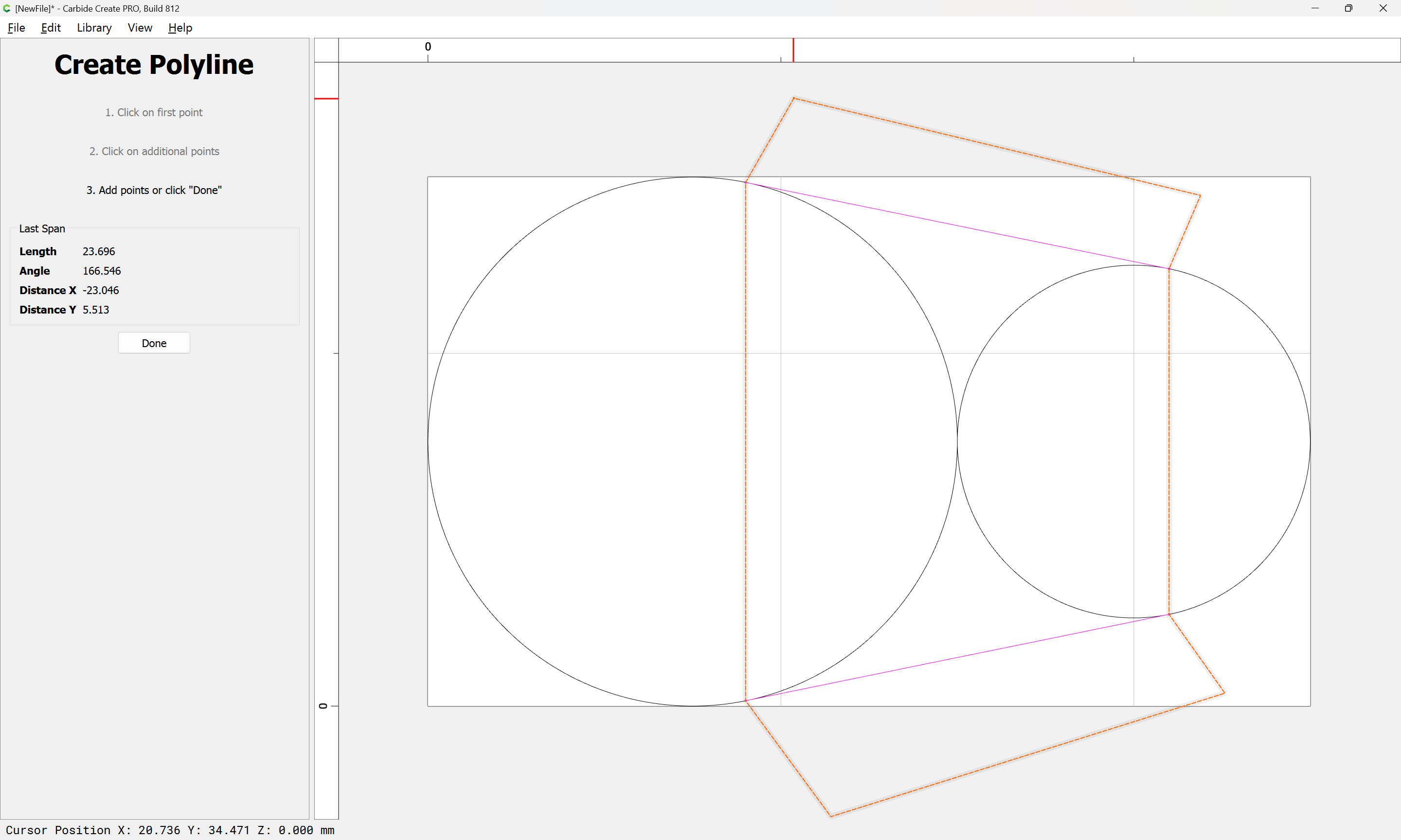
then draw the line:
Then group and re-align:
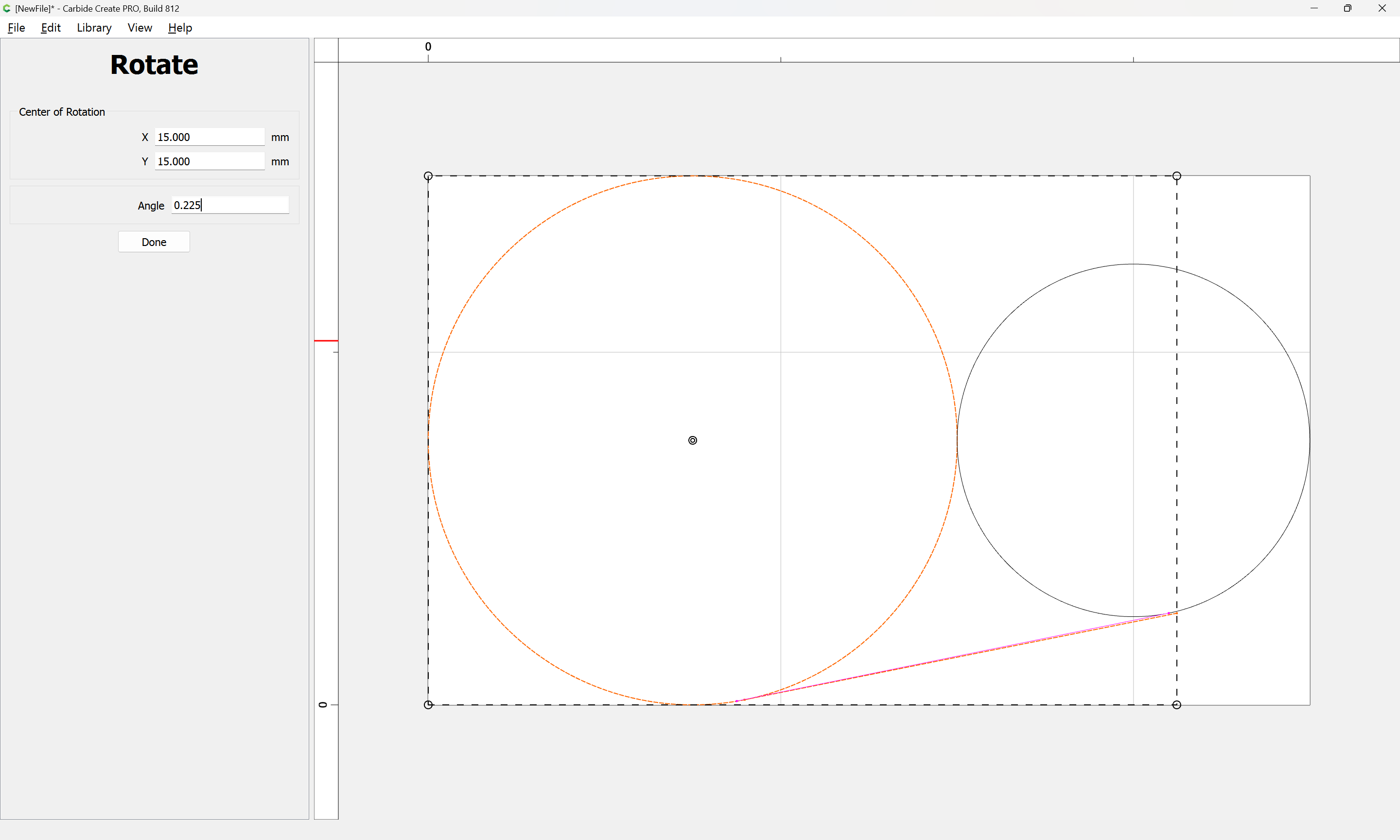
Rotate the group the same angle:

(note that filling in the center of the circle as the point of rotation will eliminate the need for later re-alignment)
Done
Repeat the rotation for each assembly, filling in the circle center each time with smaller values until the two lines line up:
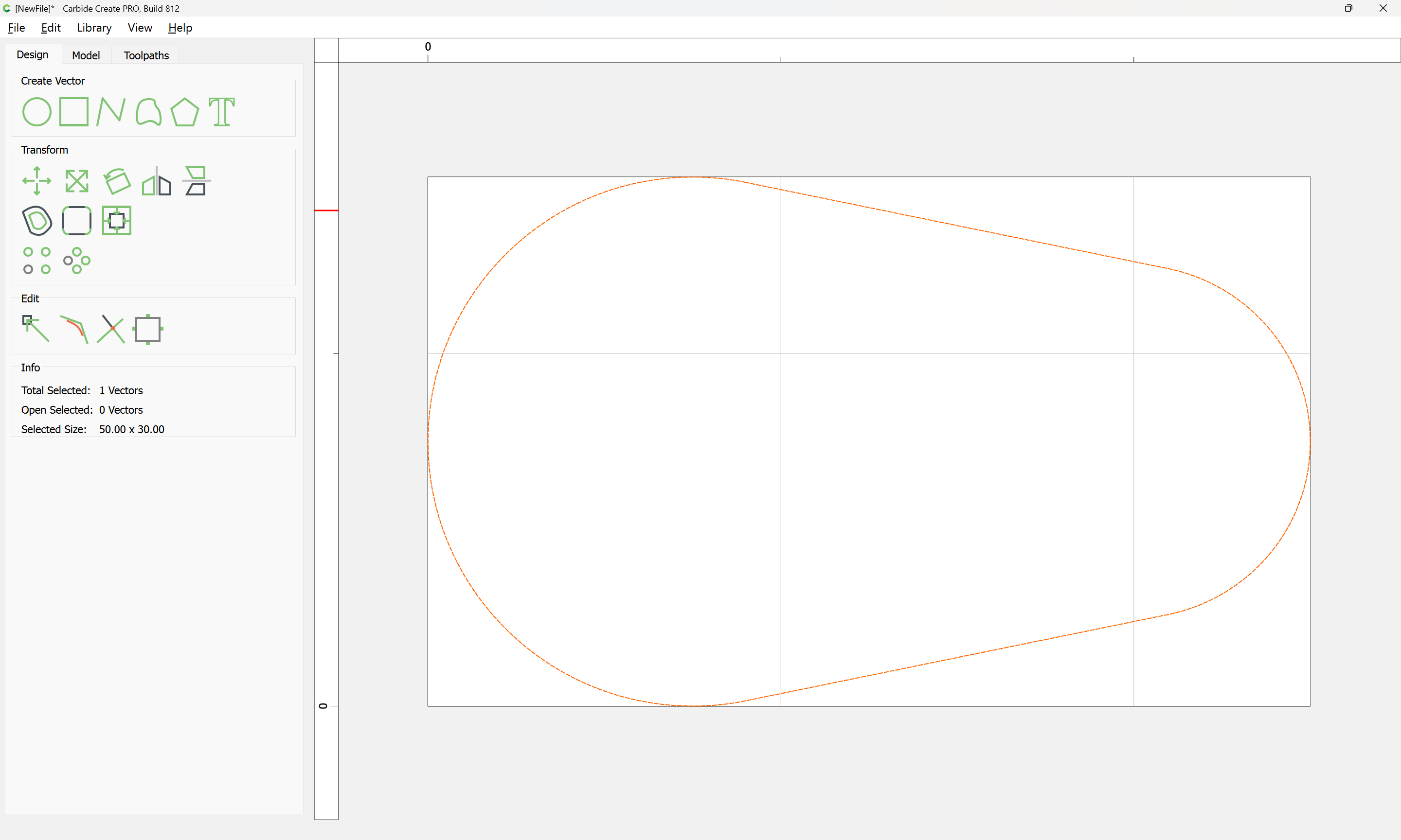
Done

Done
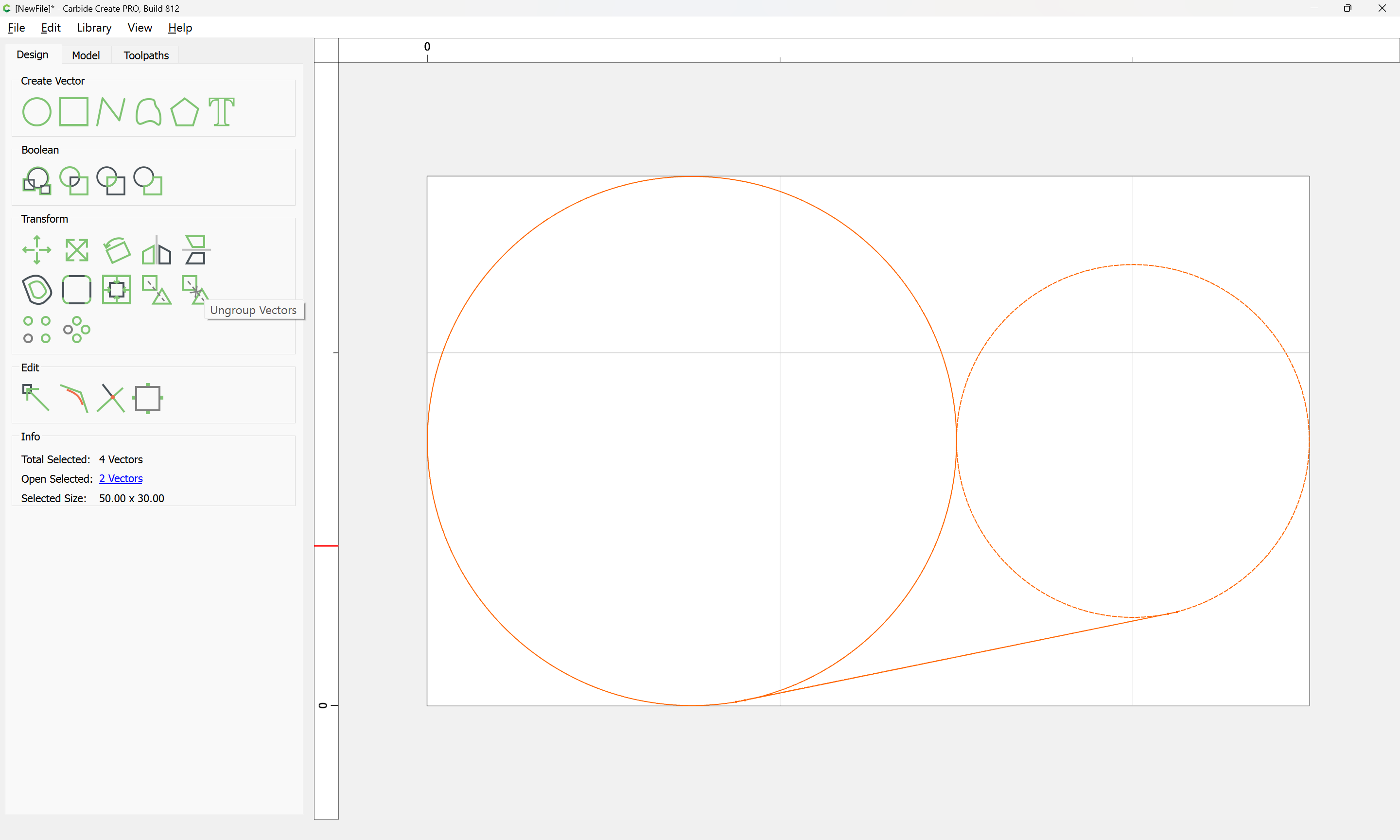
Ungroup Vectors
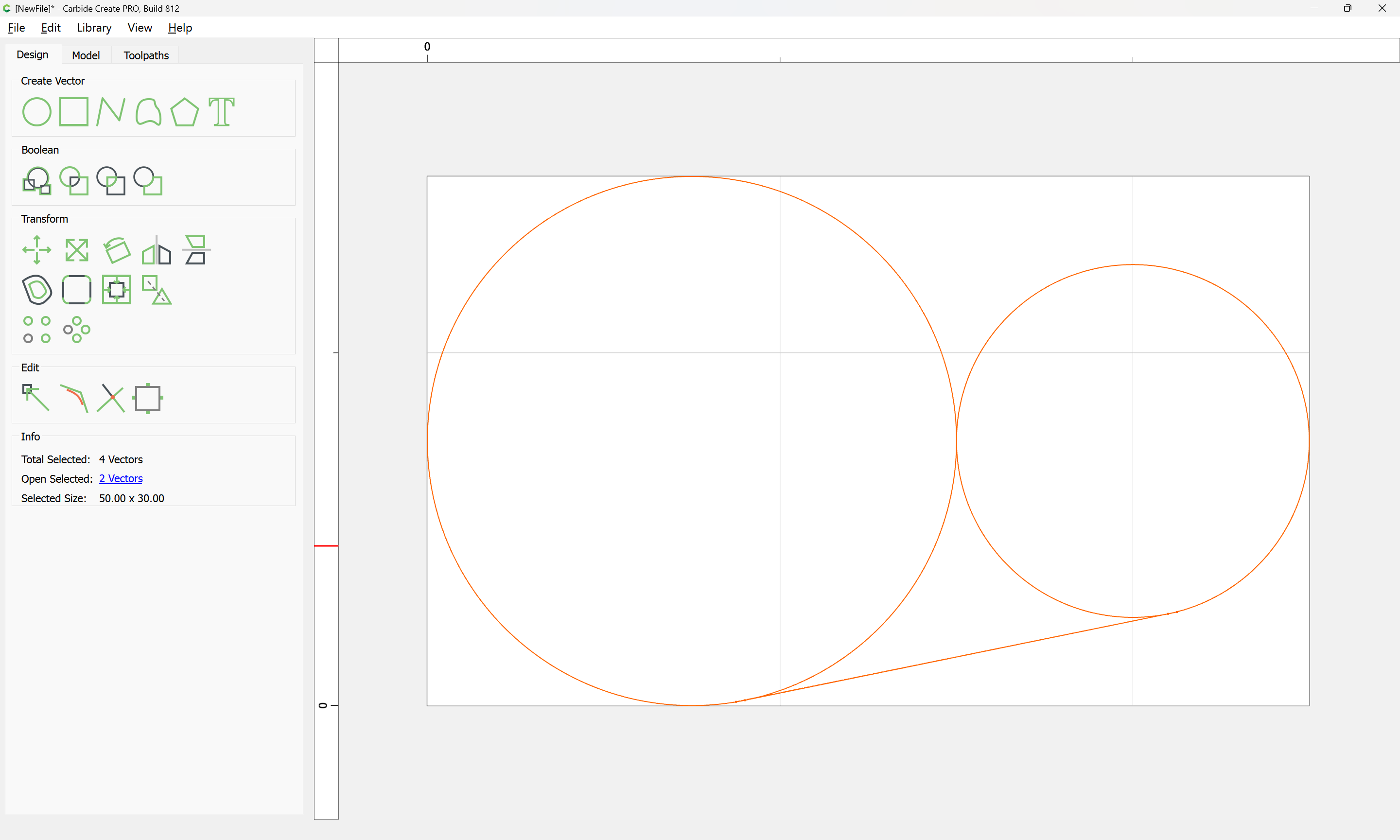
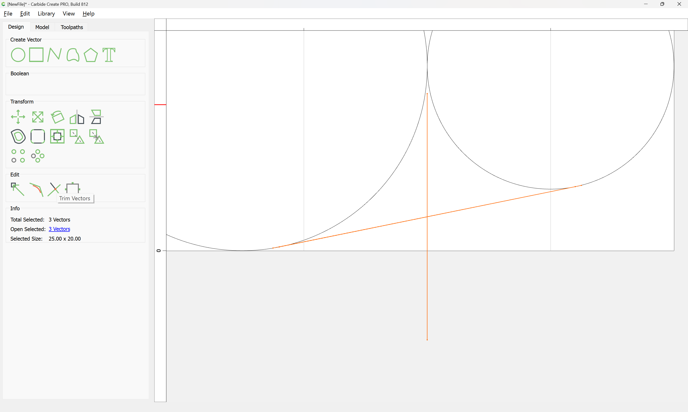
While it would be idea if one could just select the two lines and use Trim Vectors, the very shallow angles preclude this, so instead, group them:

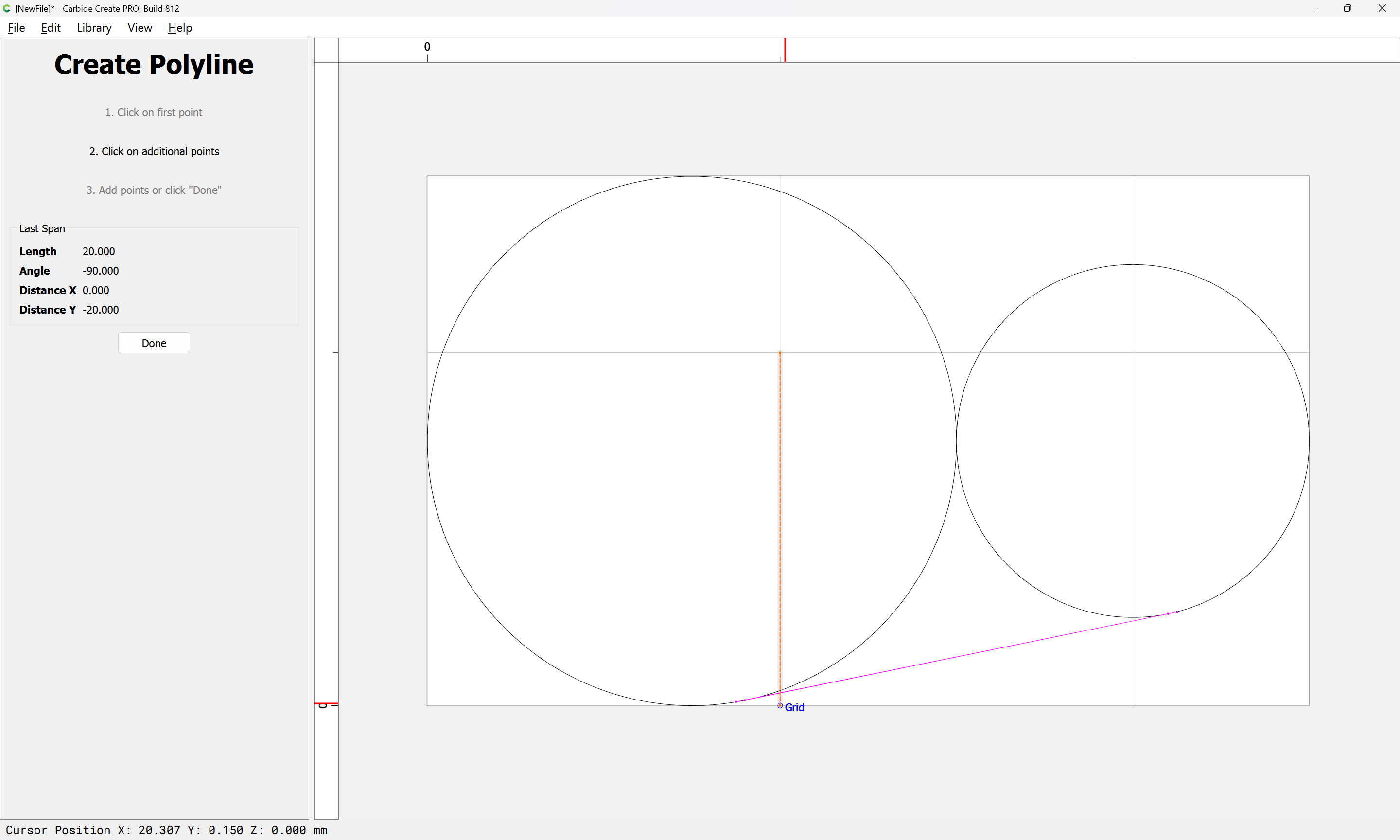
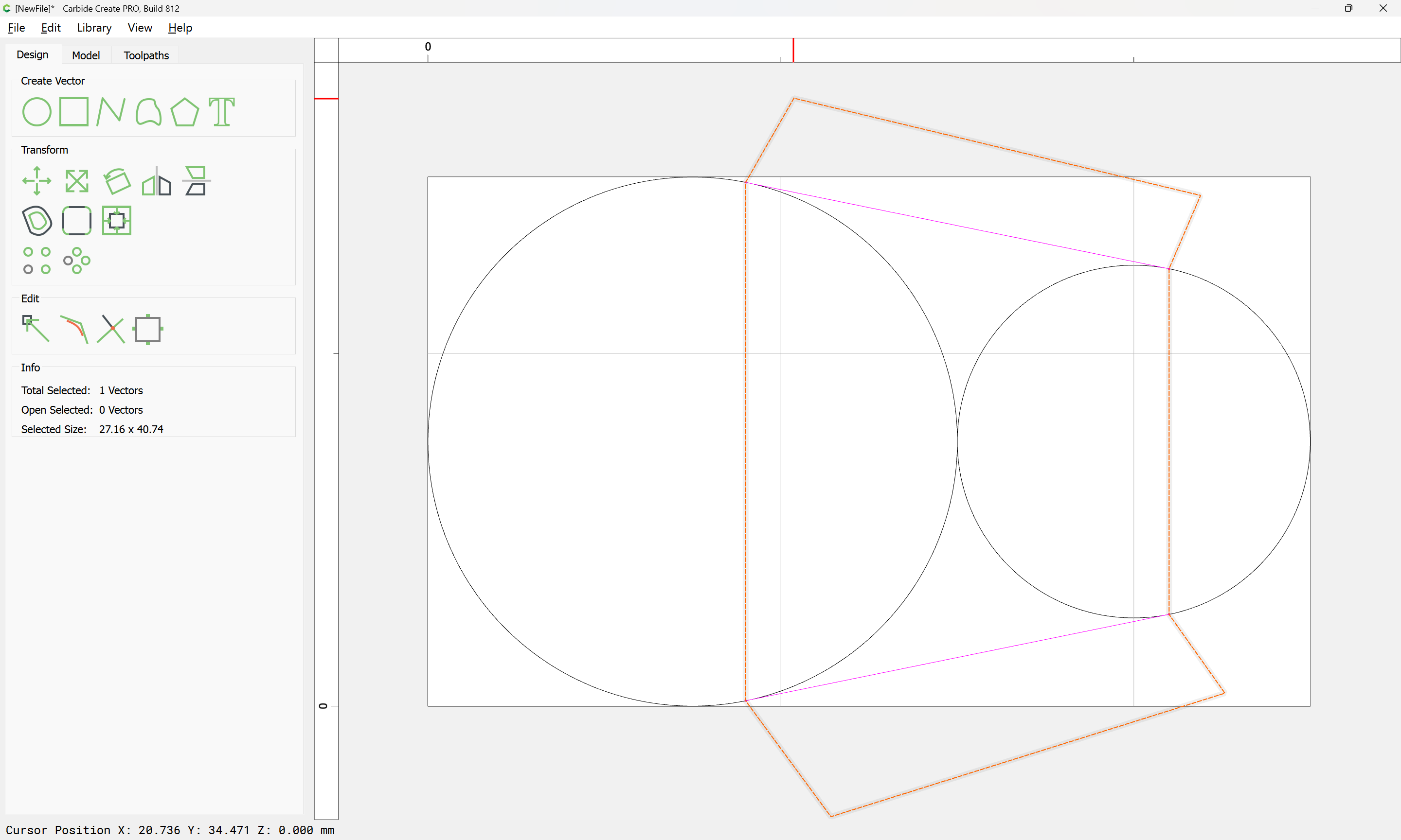
Draw a vertical line:
shift-click on the grouped lines to make them the key object:
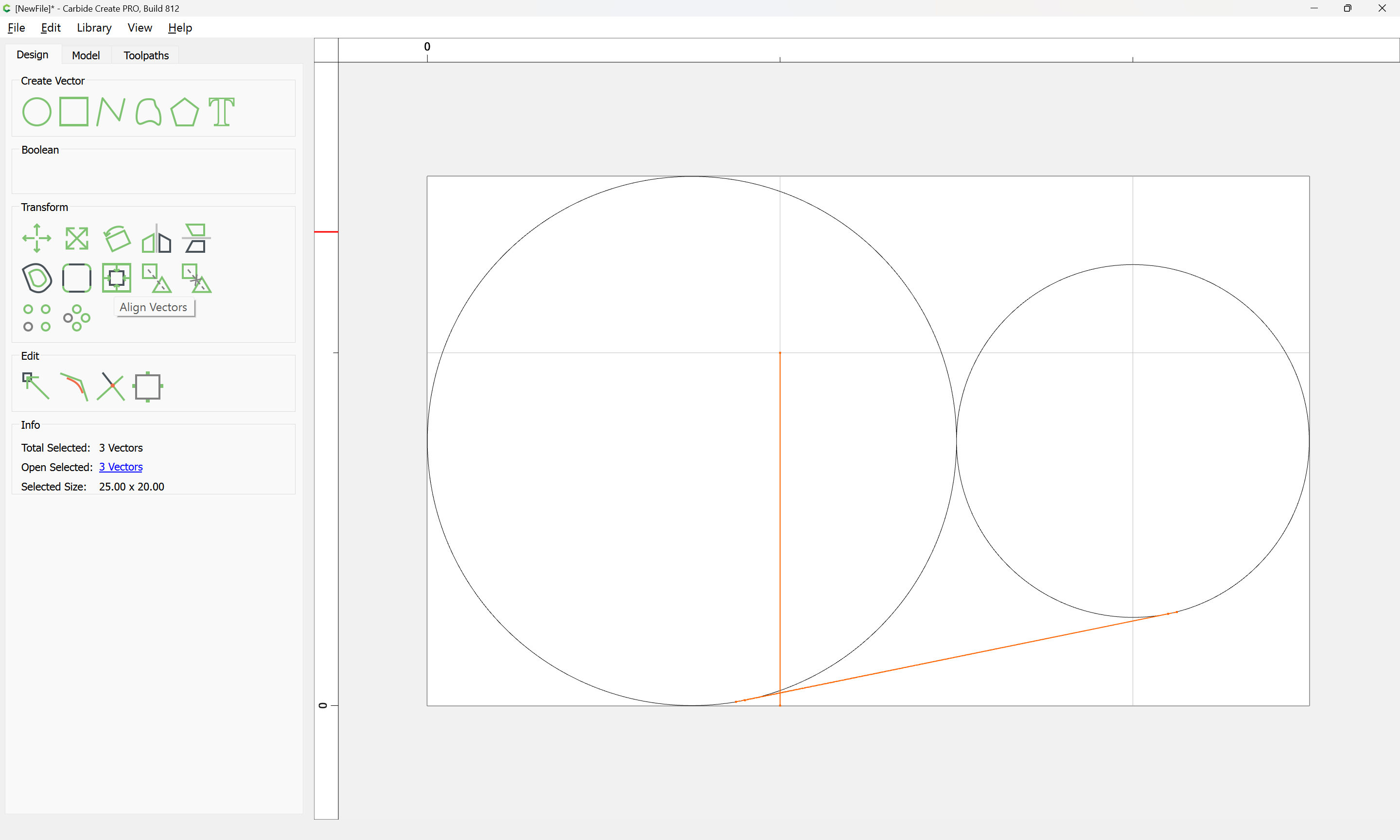
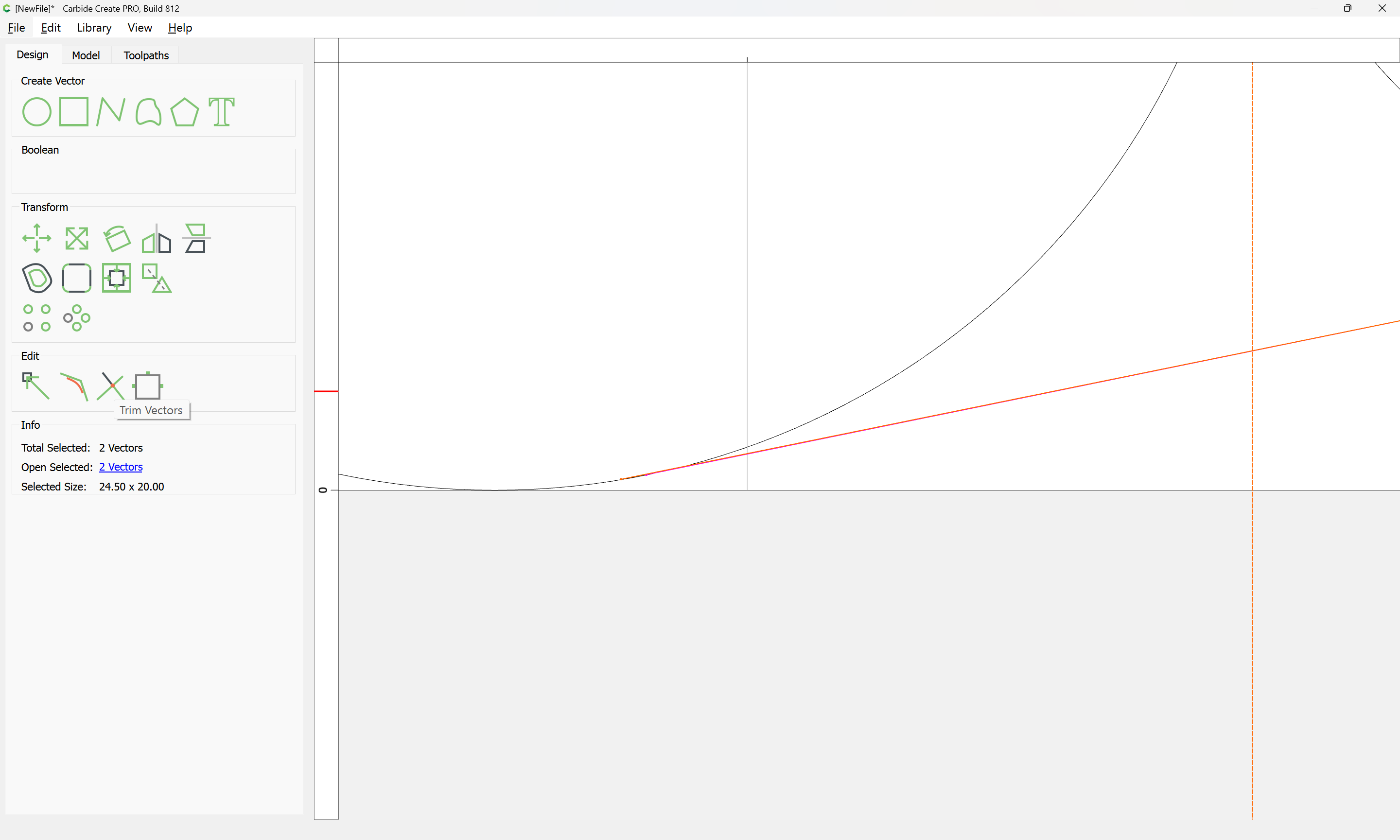
Align Vectors:
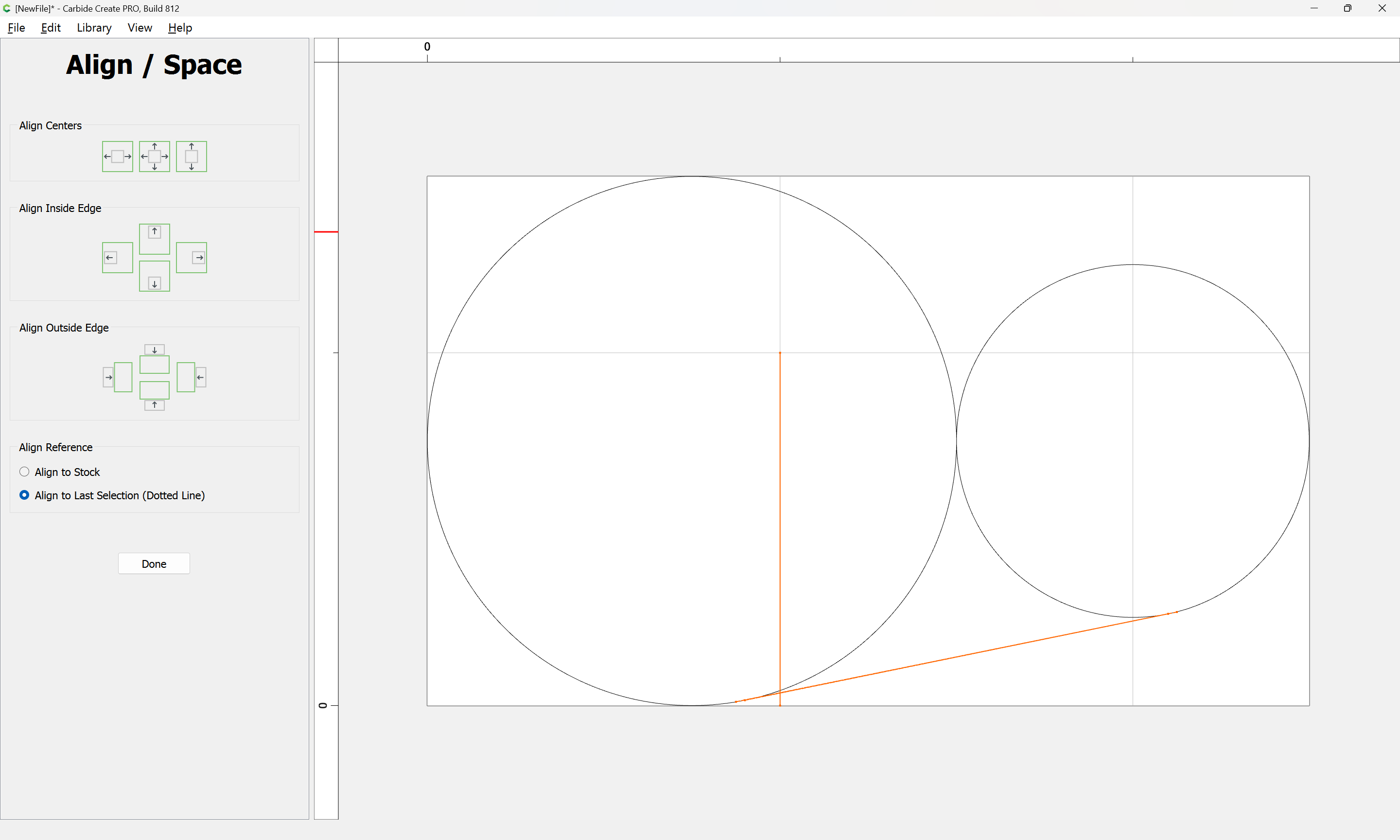
Aligning to the Center:

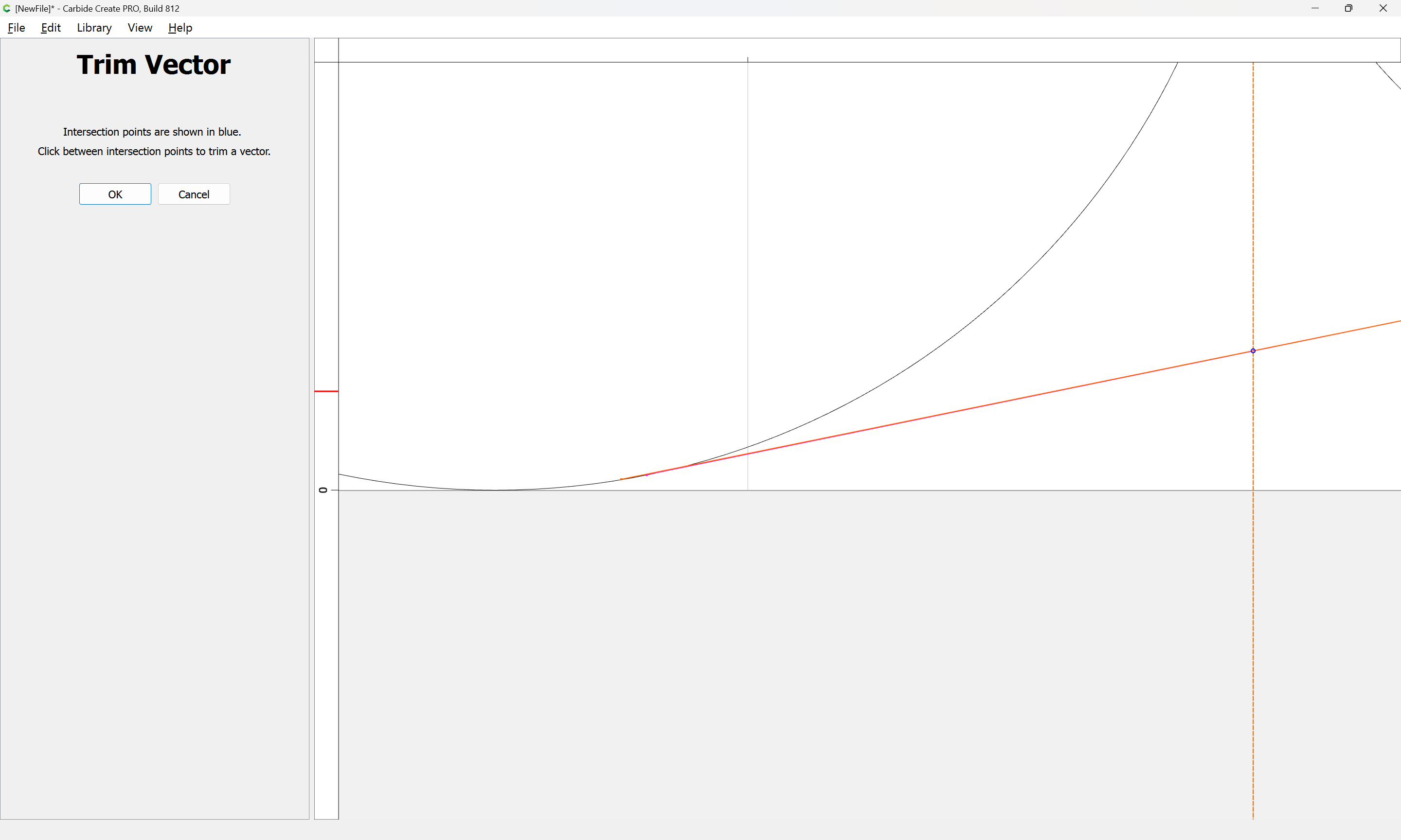
Ungroup select one of the original lines at a time, and use Trim Vectors to delete the ends which don’t line up:
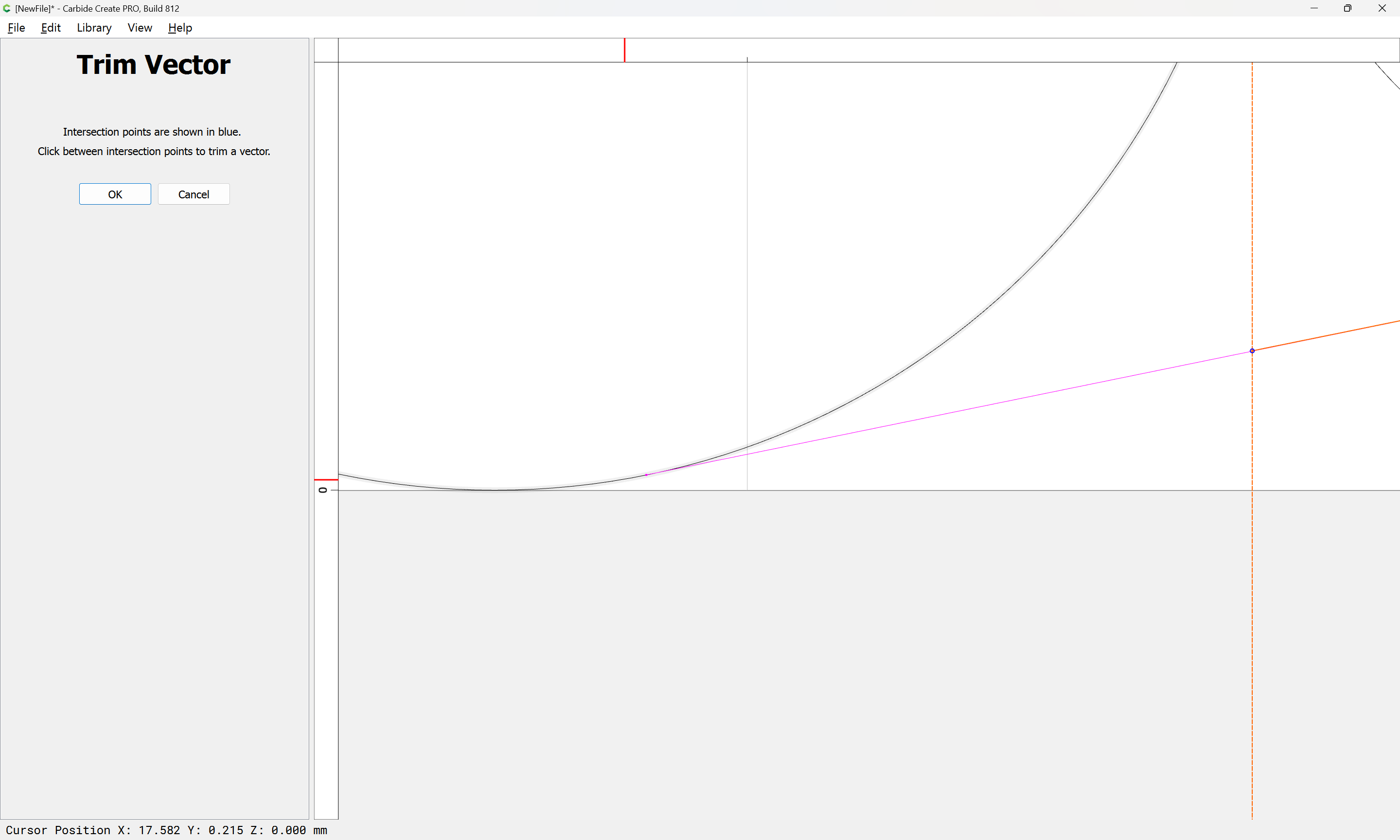
Ok

Repeat:
OK
Remove the dividing line:
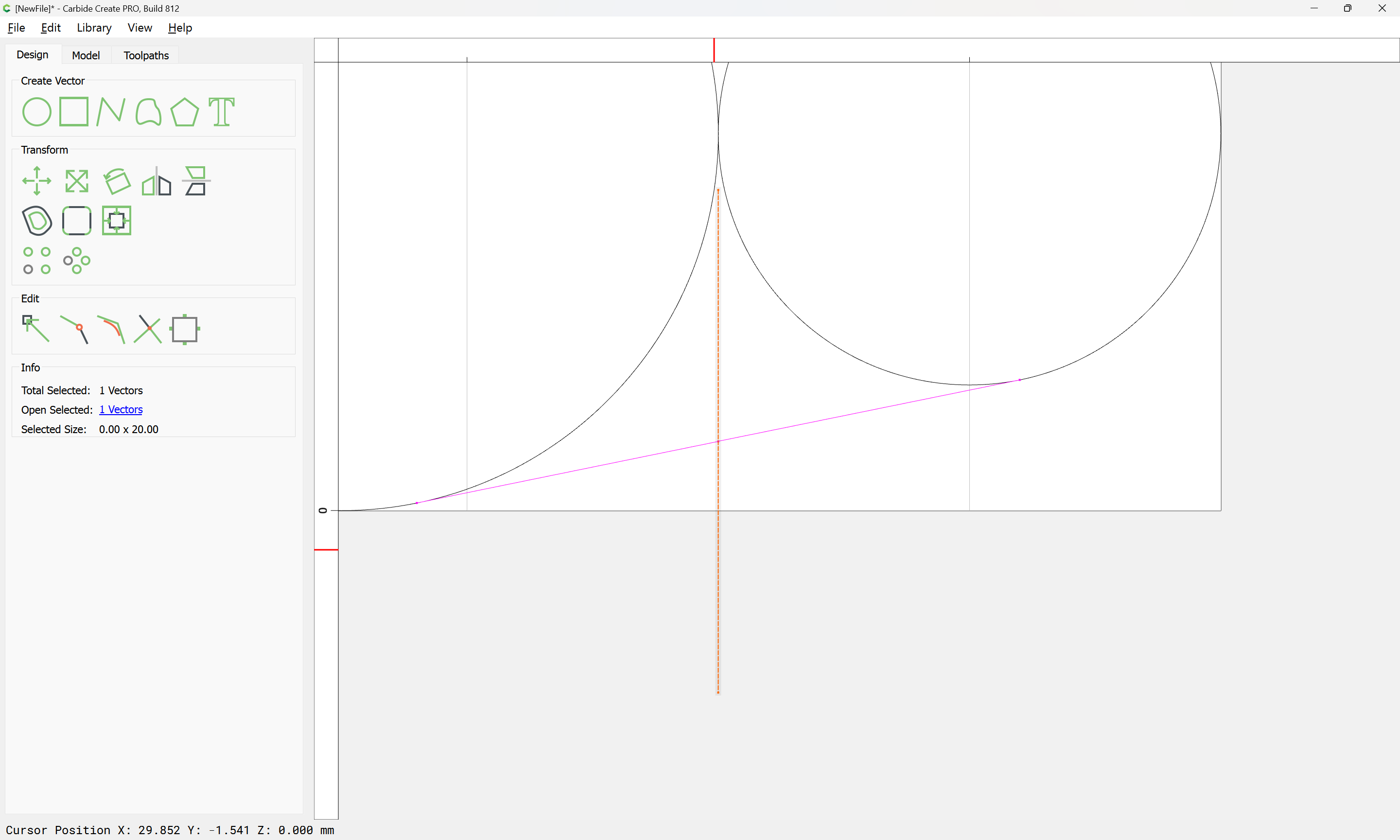
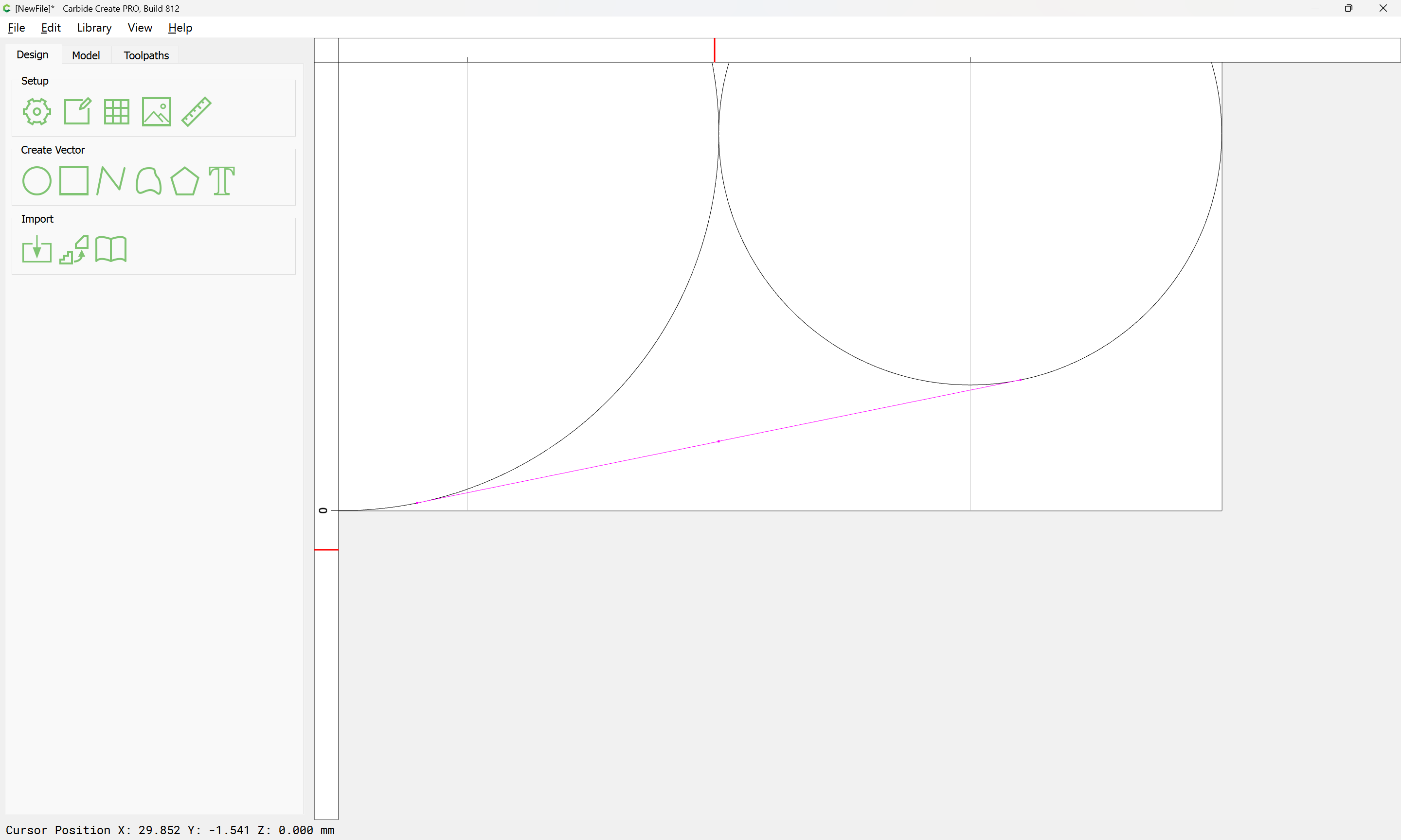
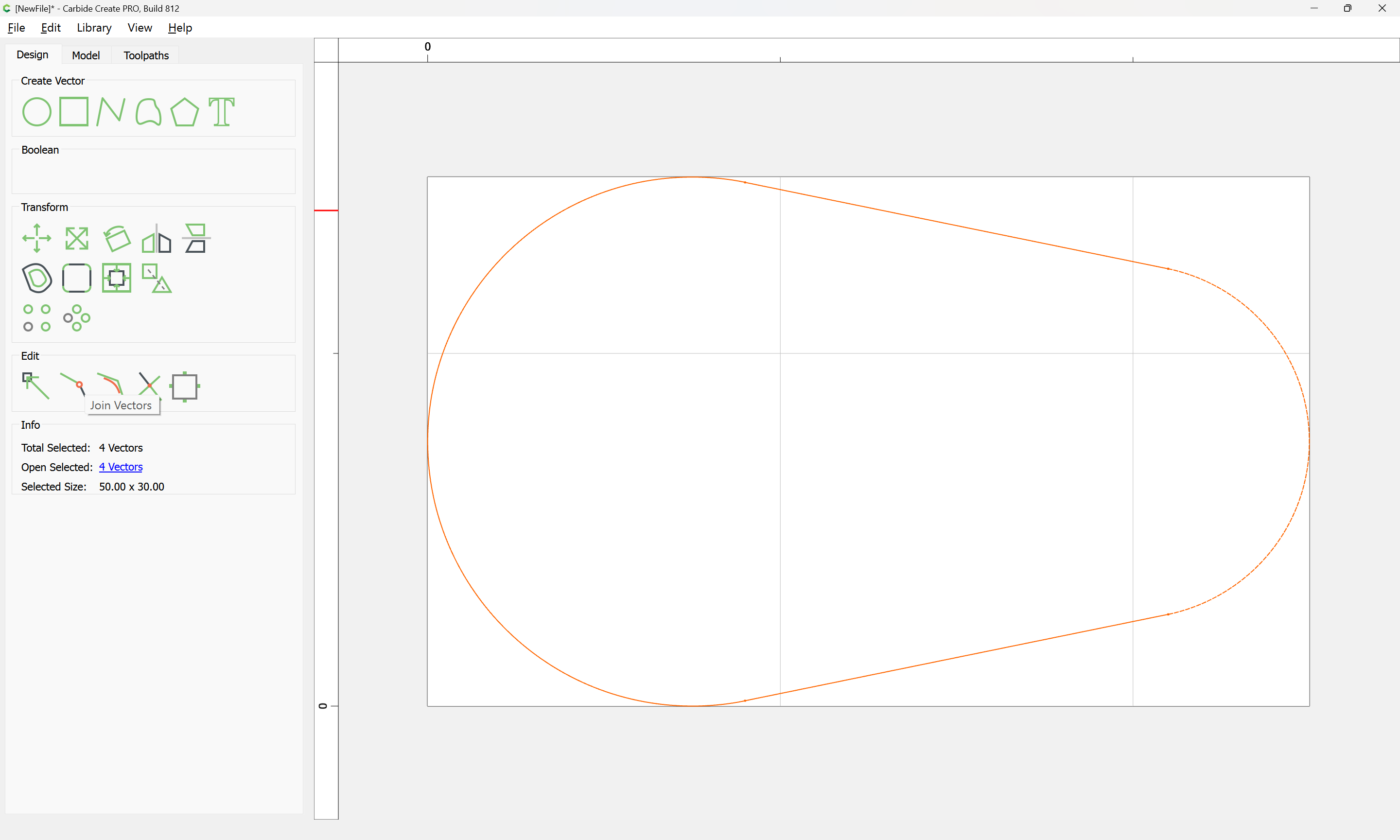
Select the two remaining lines:
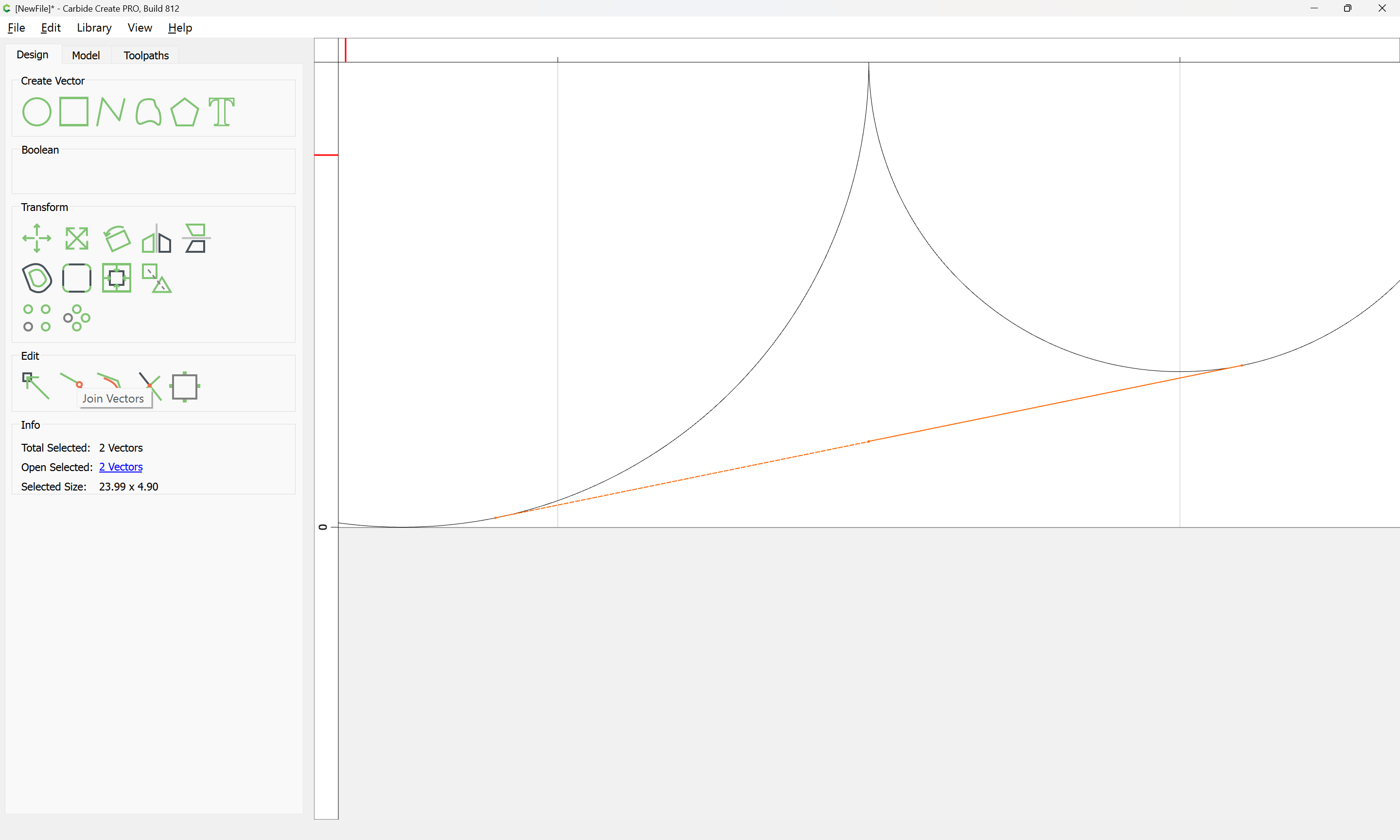
Join Vectors:
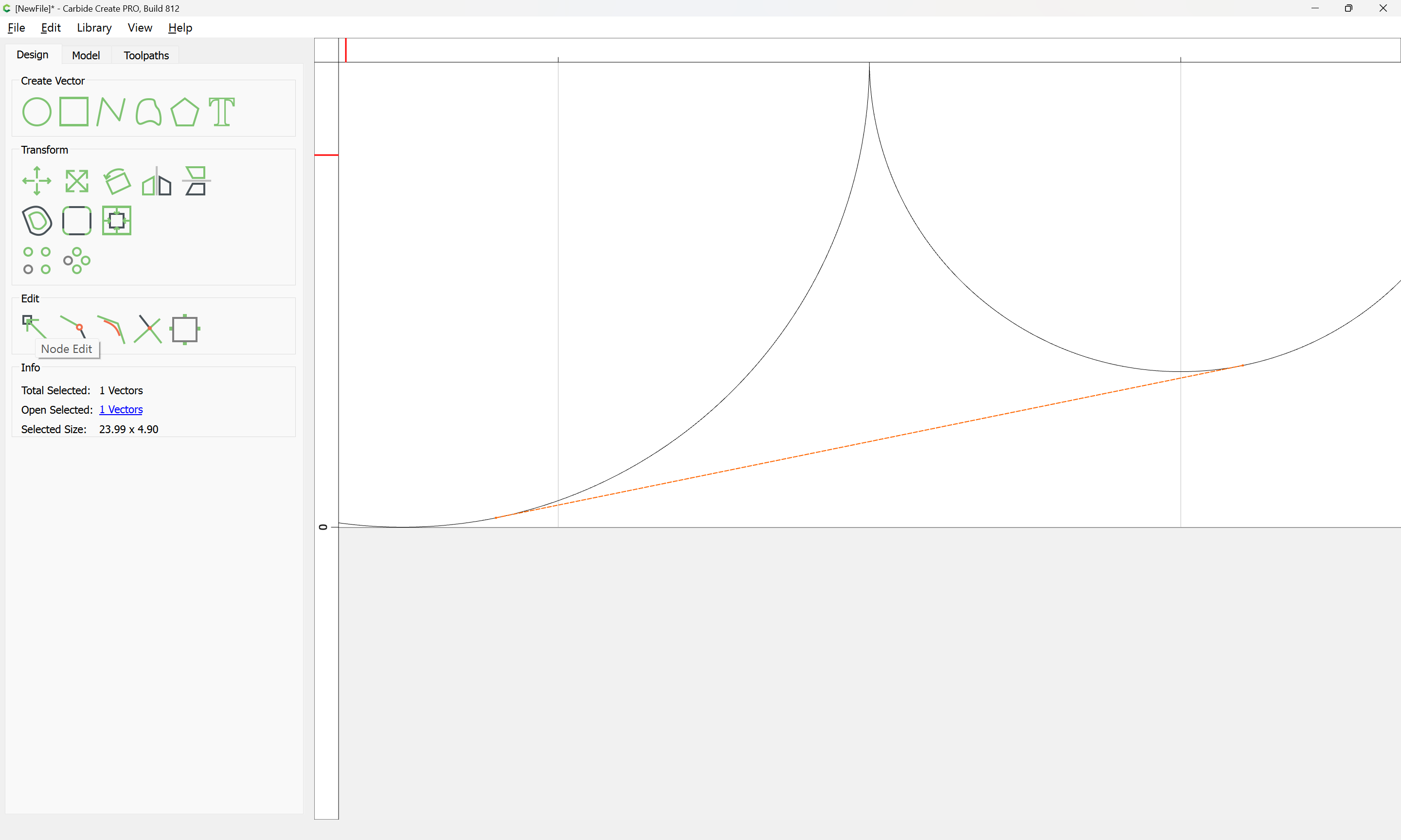
Node Edit:

Select and delete the central node:
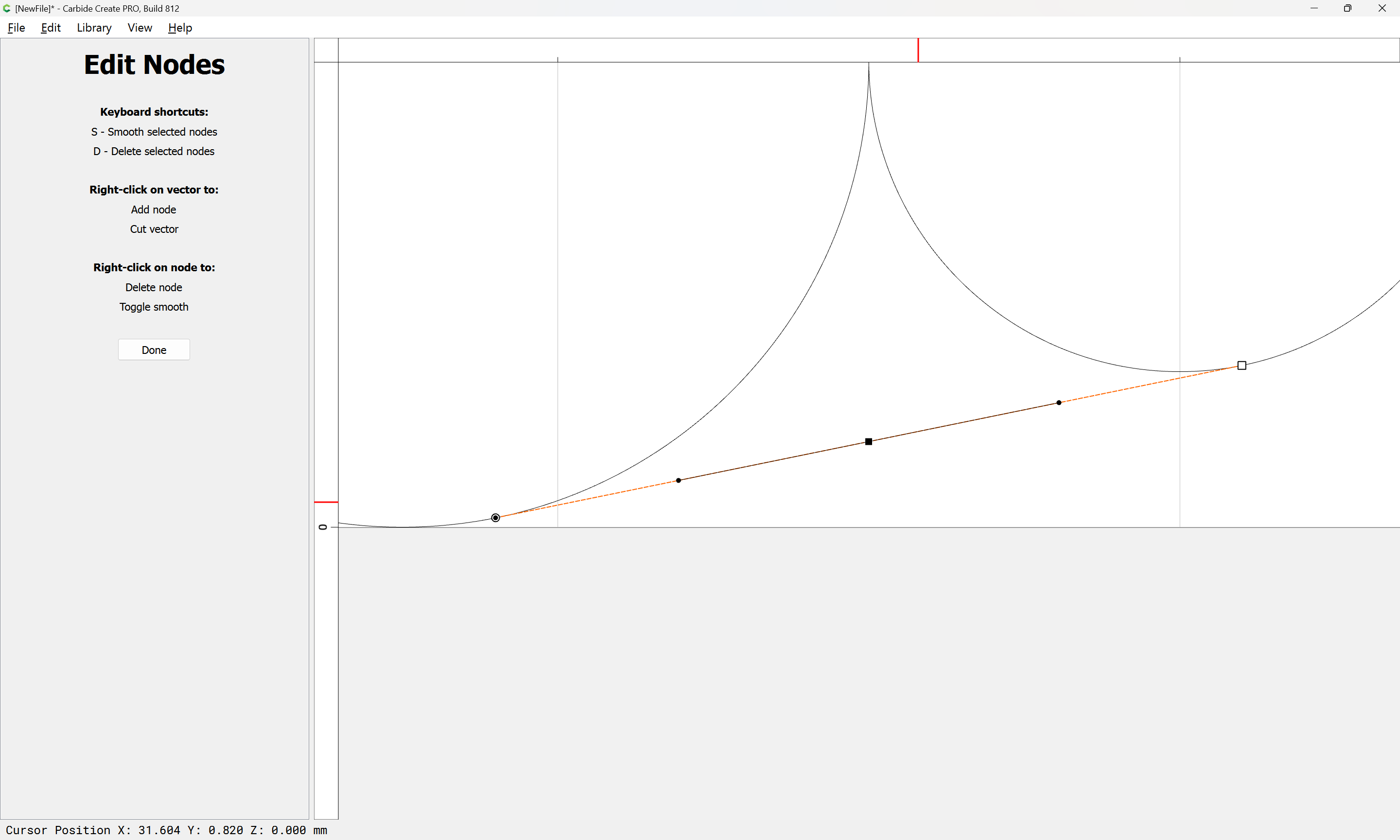
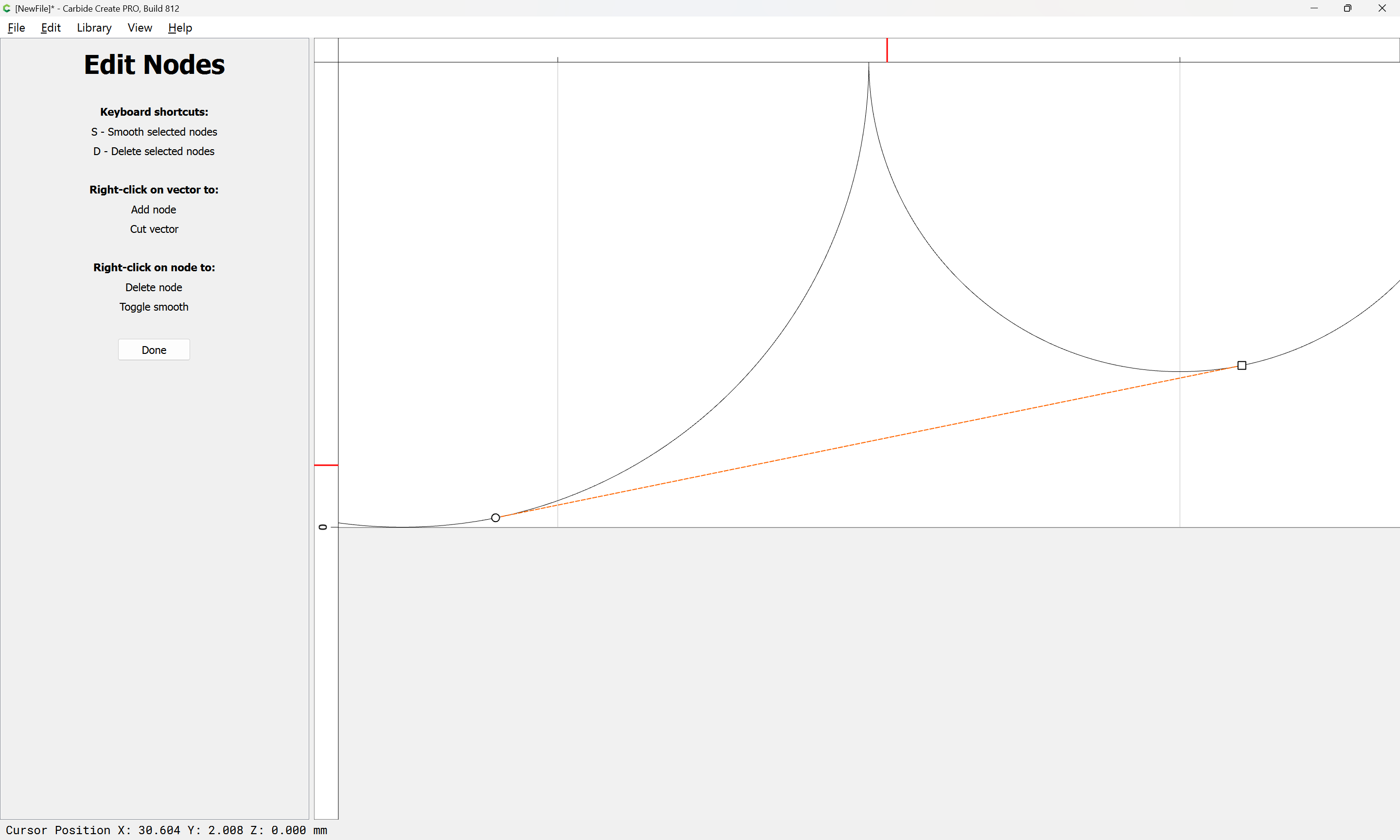
Done
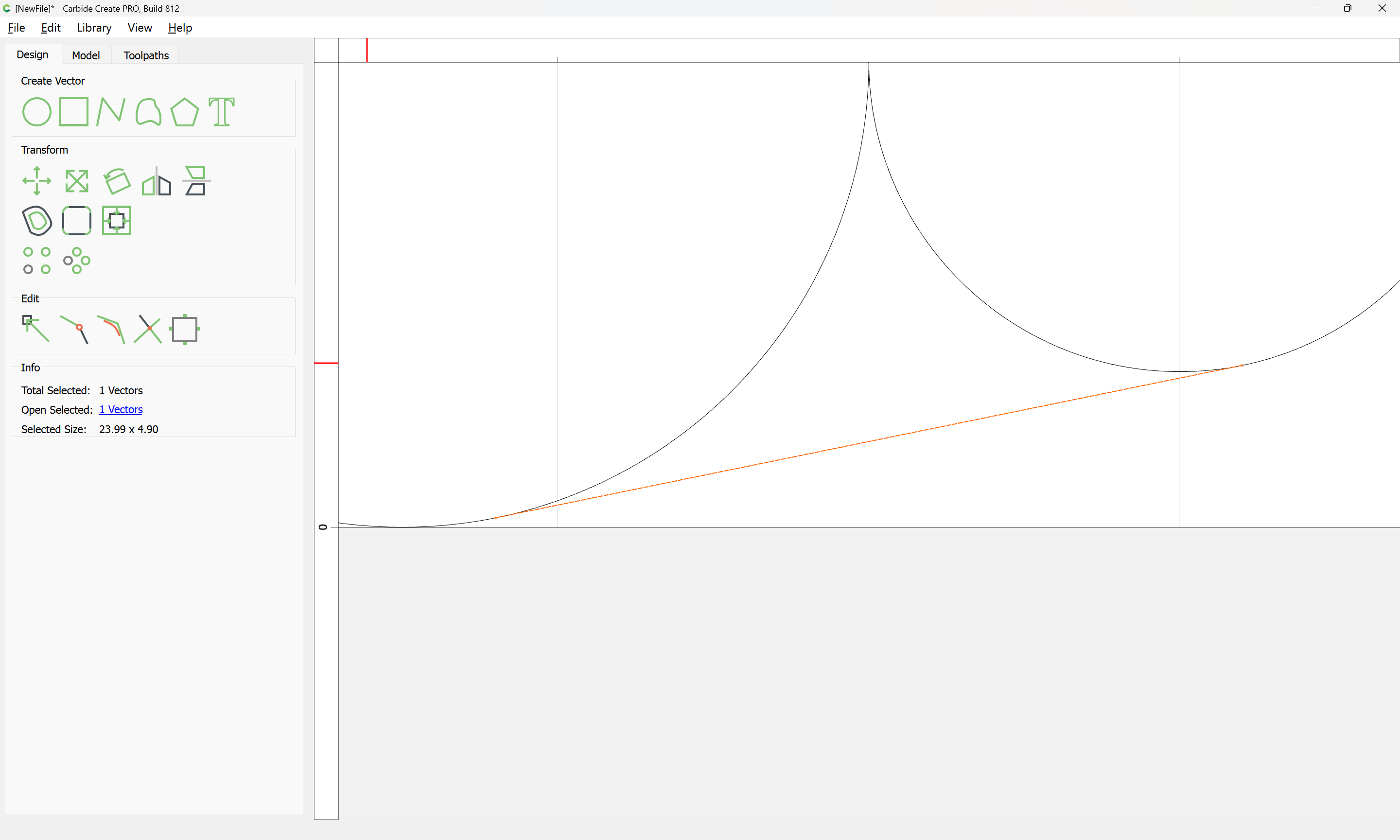
Duplicate the object in place:
Select it and the larger circle:

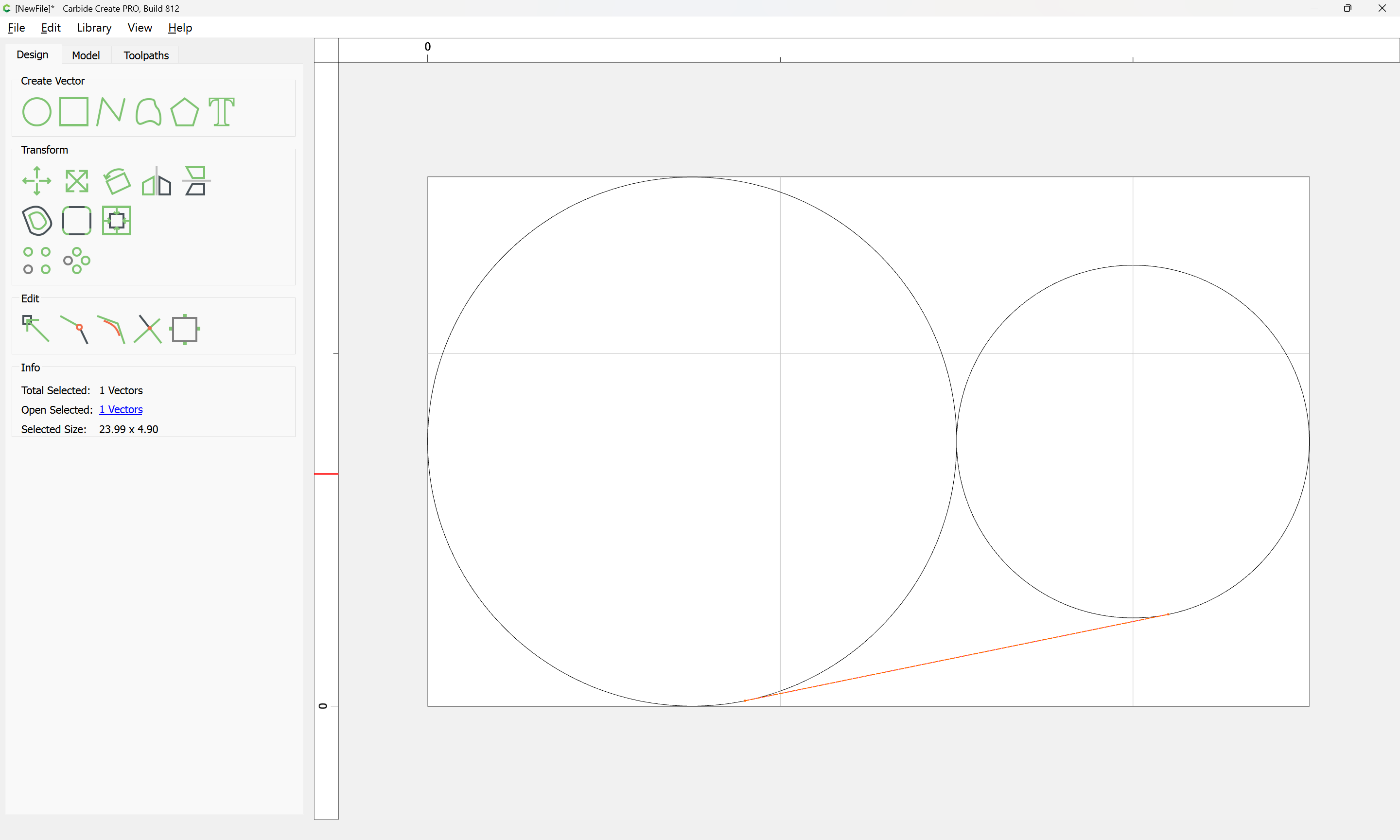
Mirror Vertical:
Draw in lines which will divide the circles where they meet the tangent lines:
Using the nodes to ensure things line up

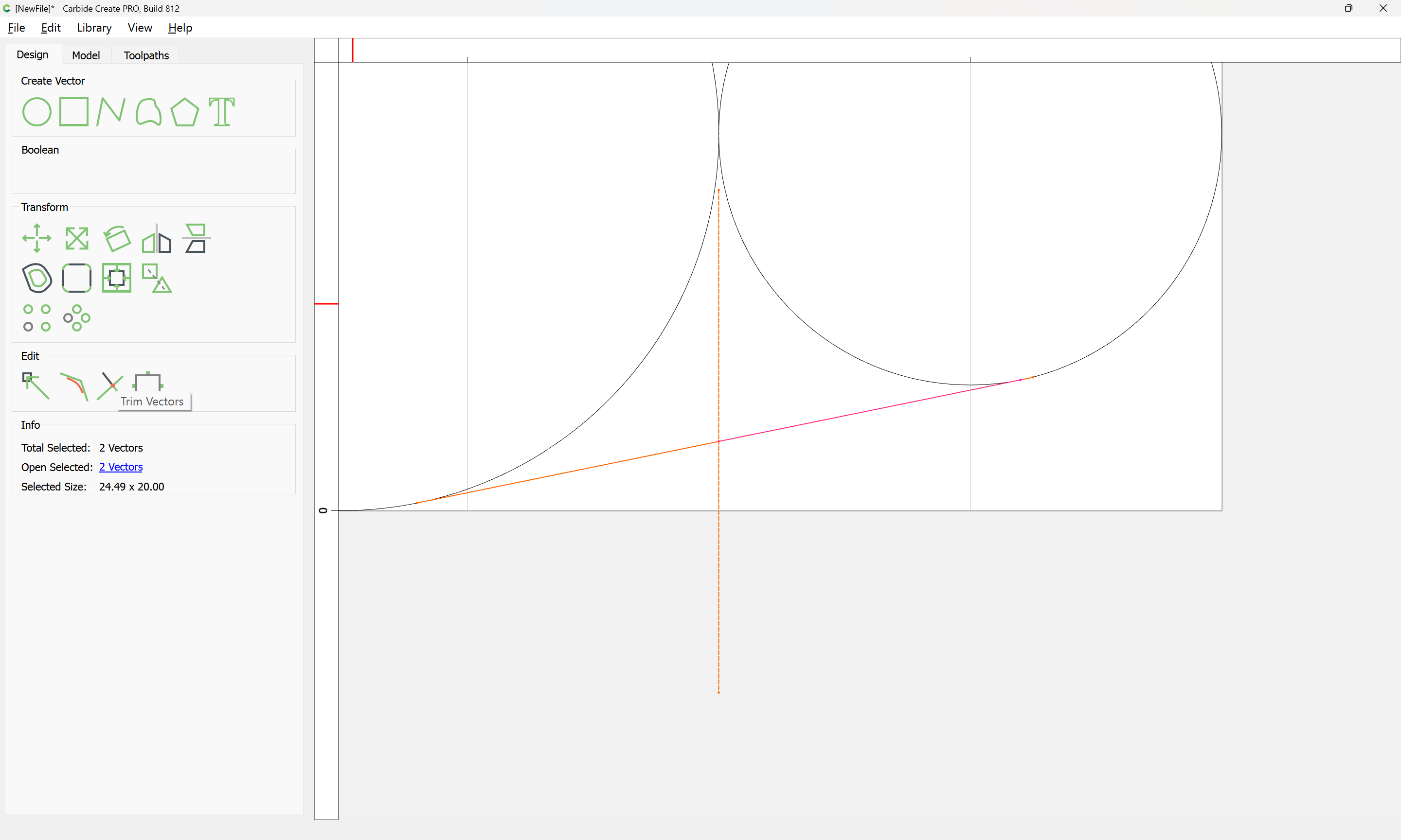
Shift-click on the two circles to add them to the selection:
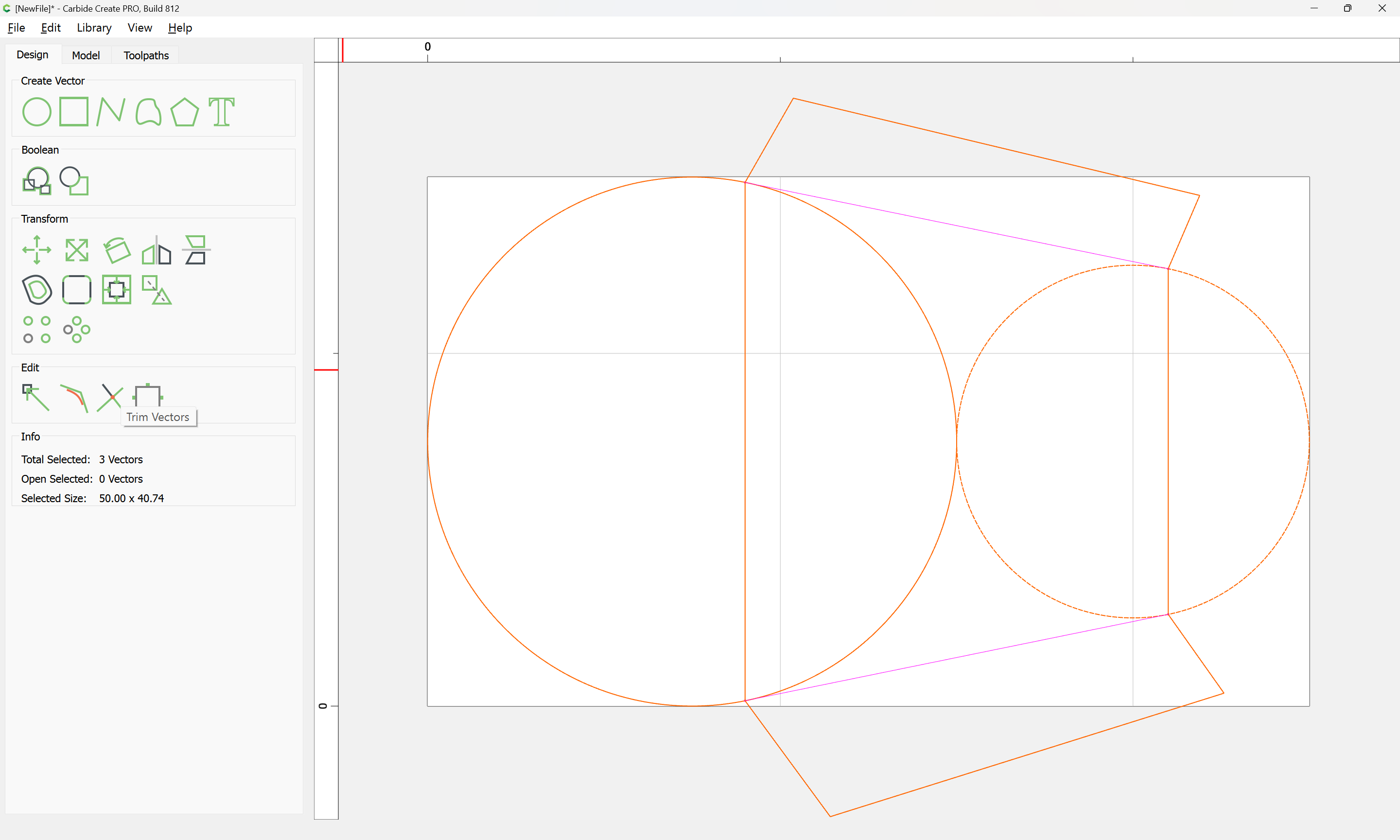
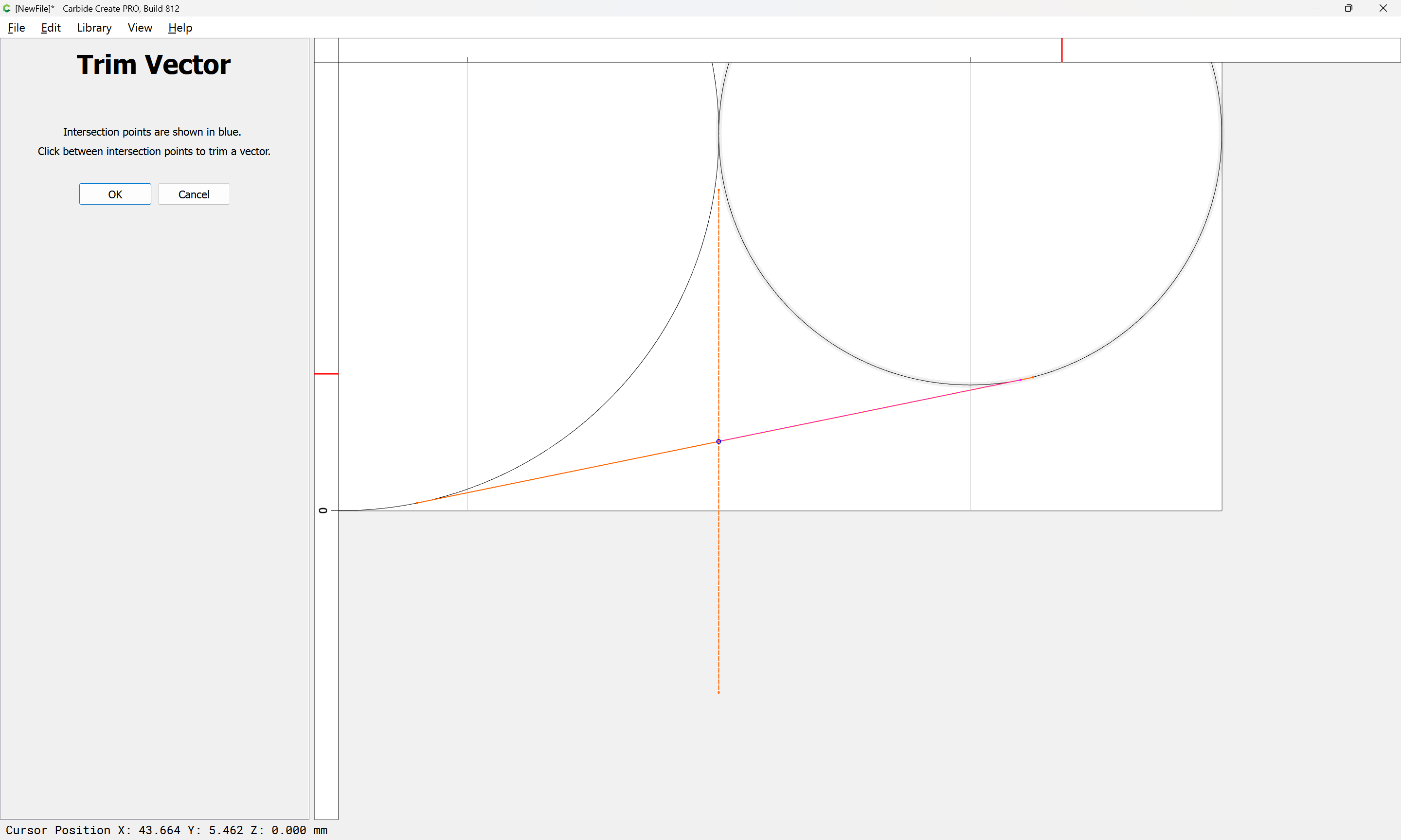
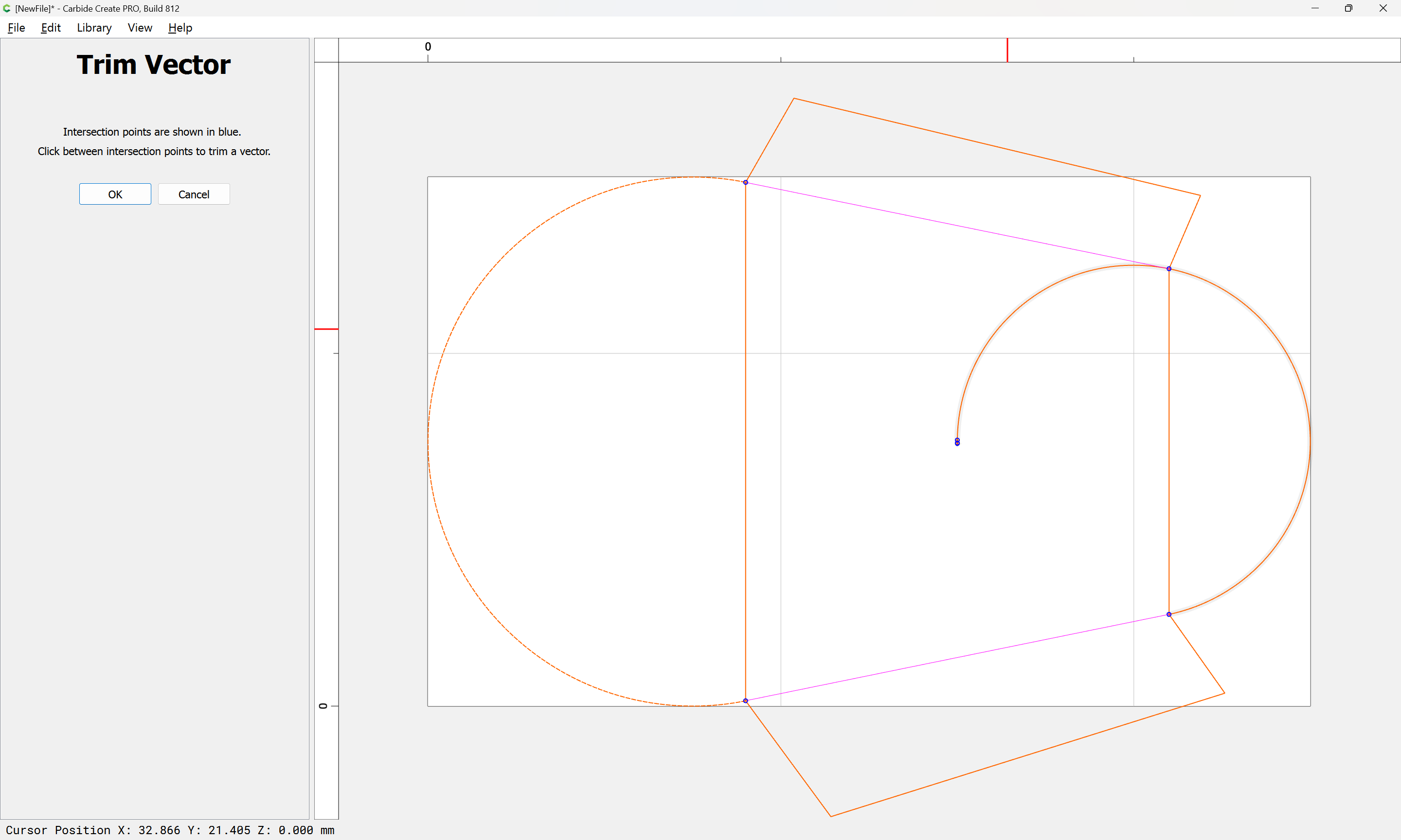
Trim Vectors
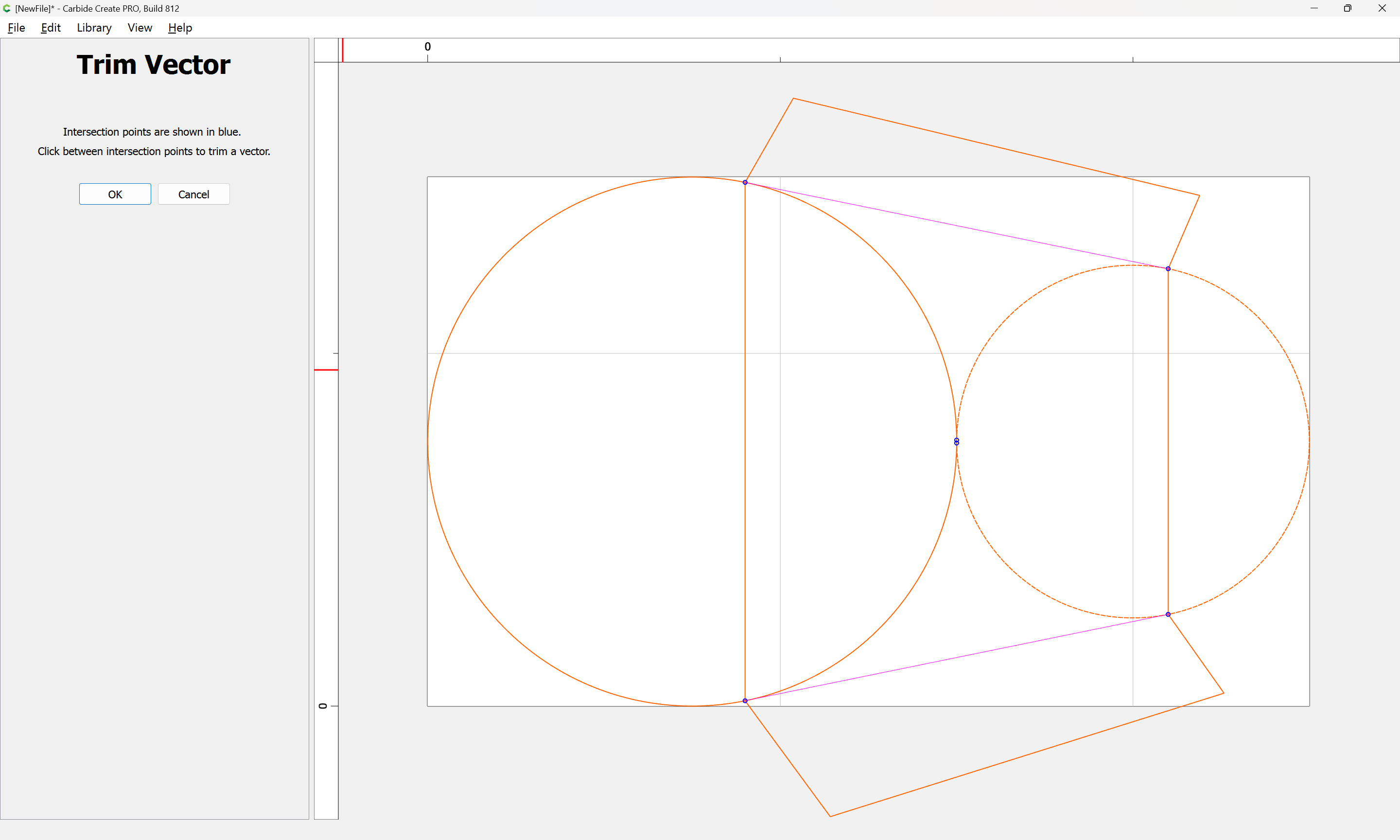
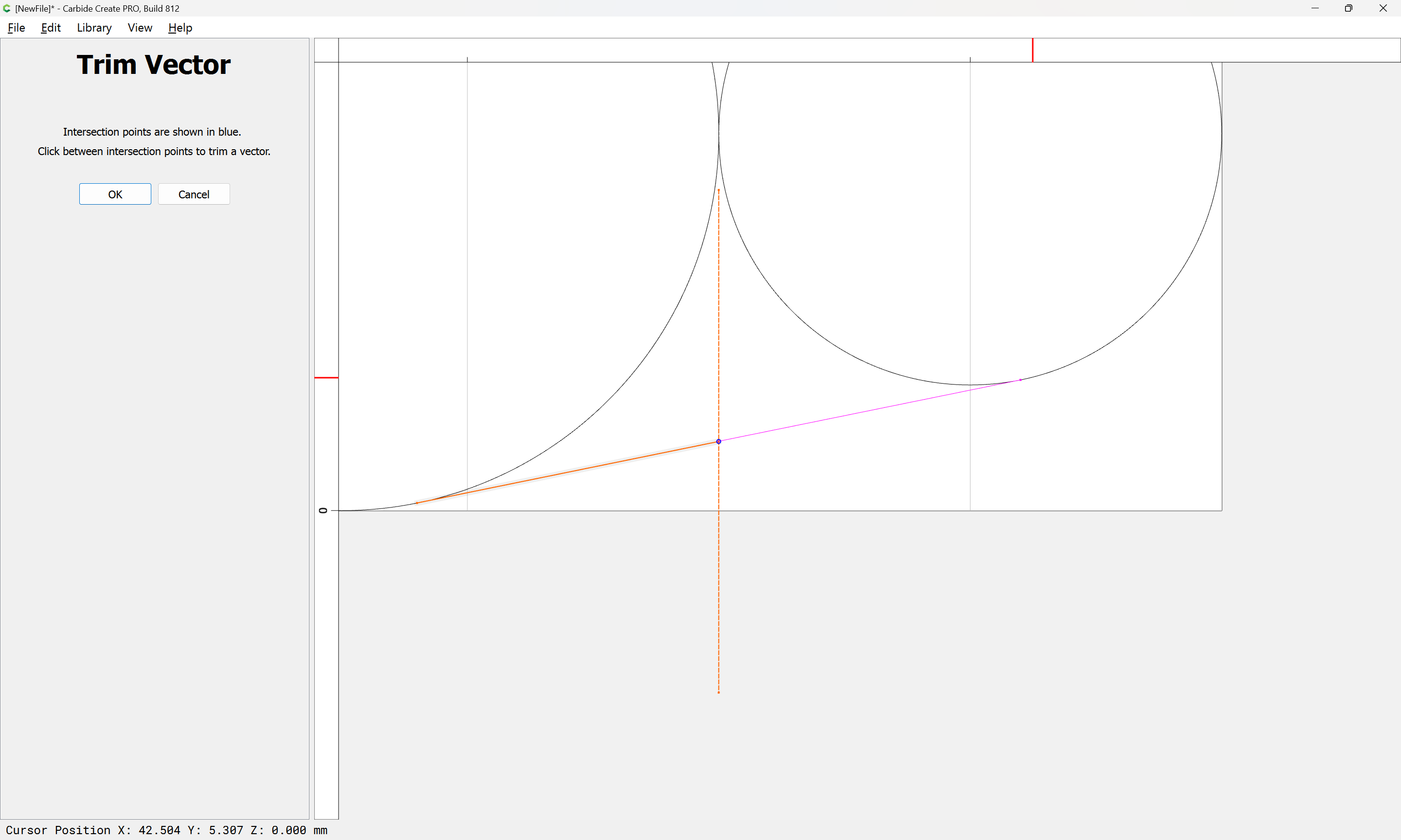
Click to remove what is not wanted:
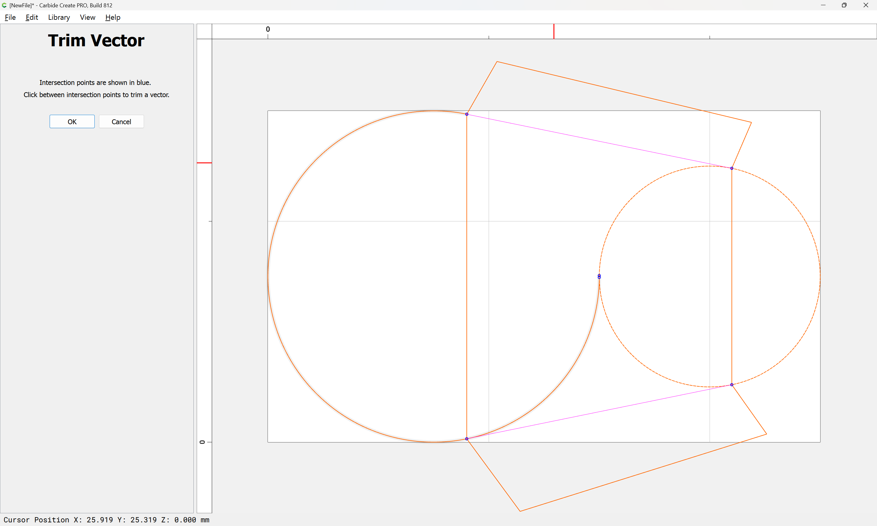
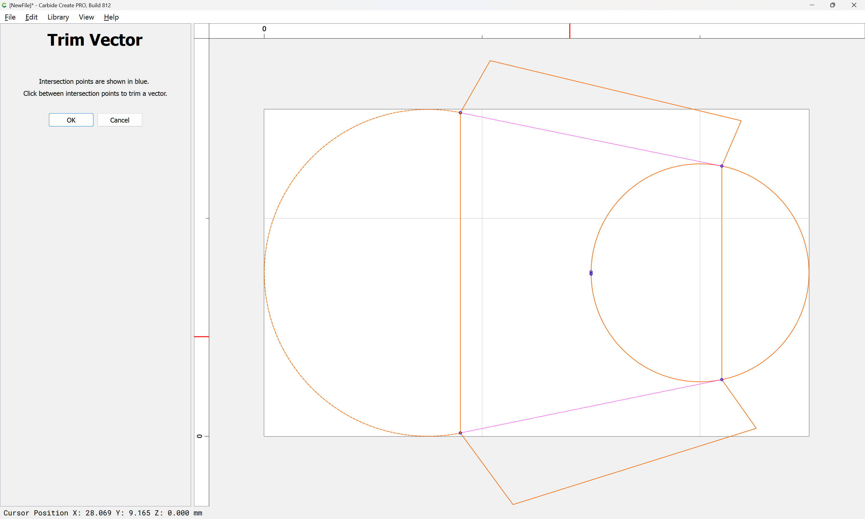
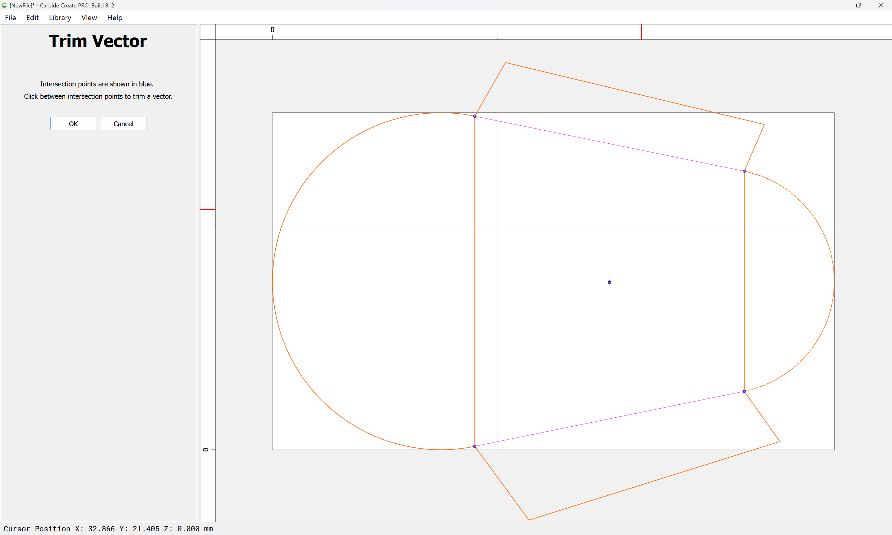
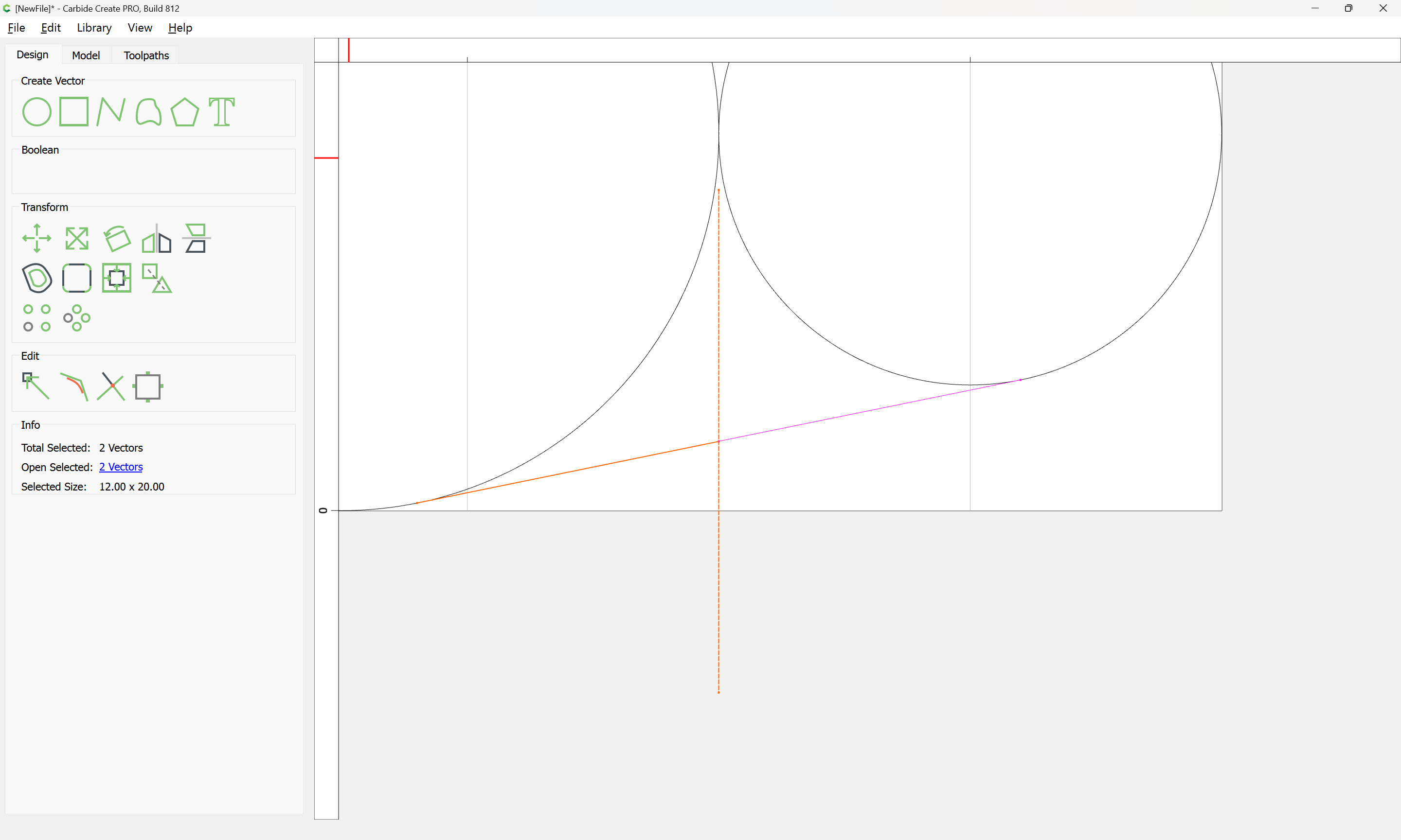
OK
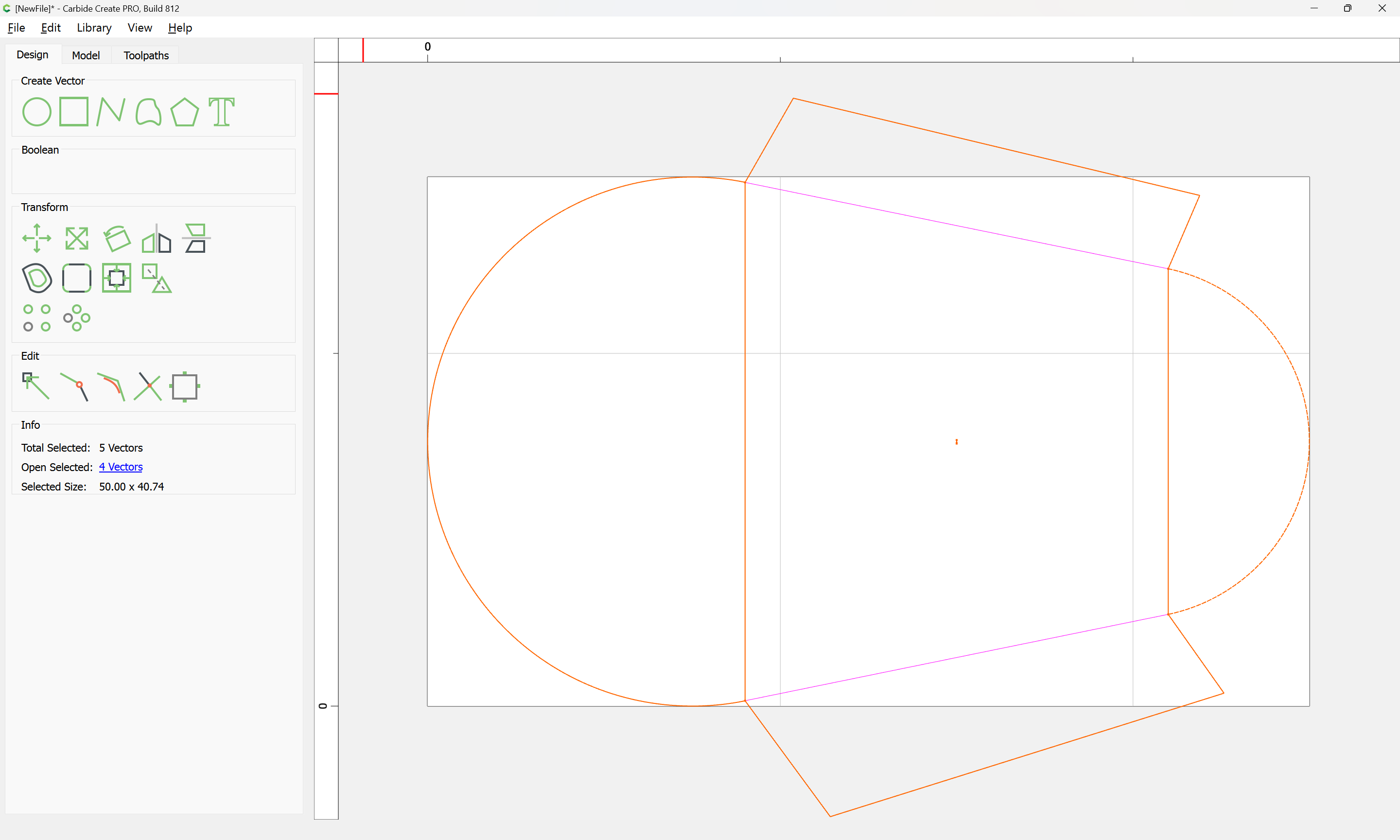
Delete the no longer necessary geometry:
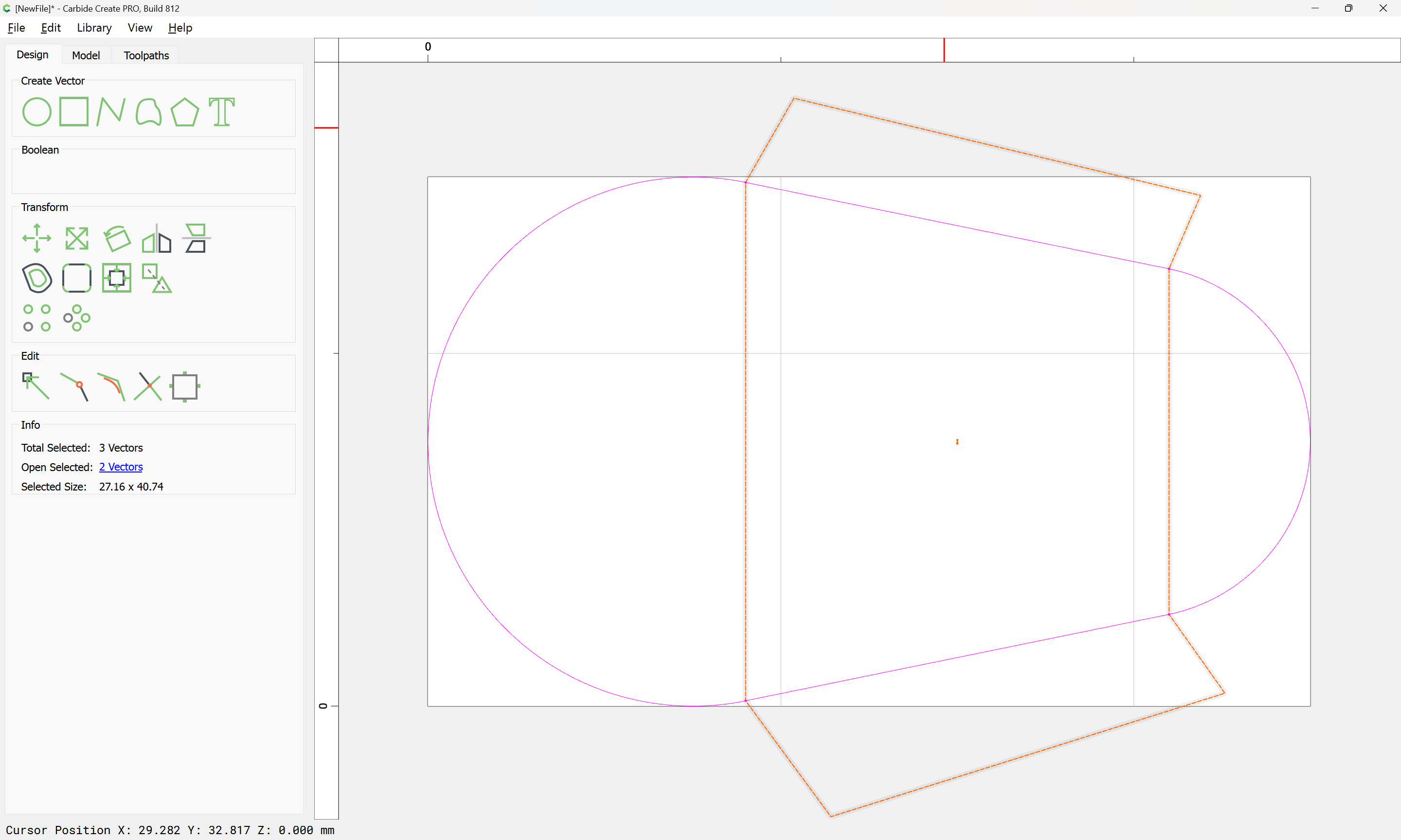

Select everything:
Join Vectors: