How to create the shape of two circles connected by tangent lines in Carbide Create?

I’m hoping someone can assist me with creating the following shape in Carbide Create:

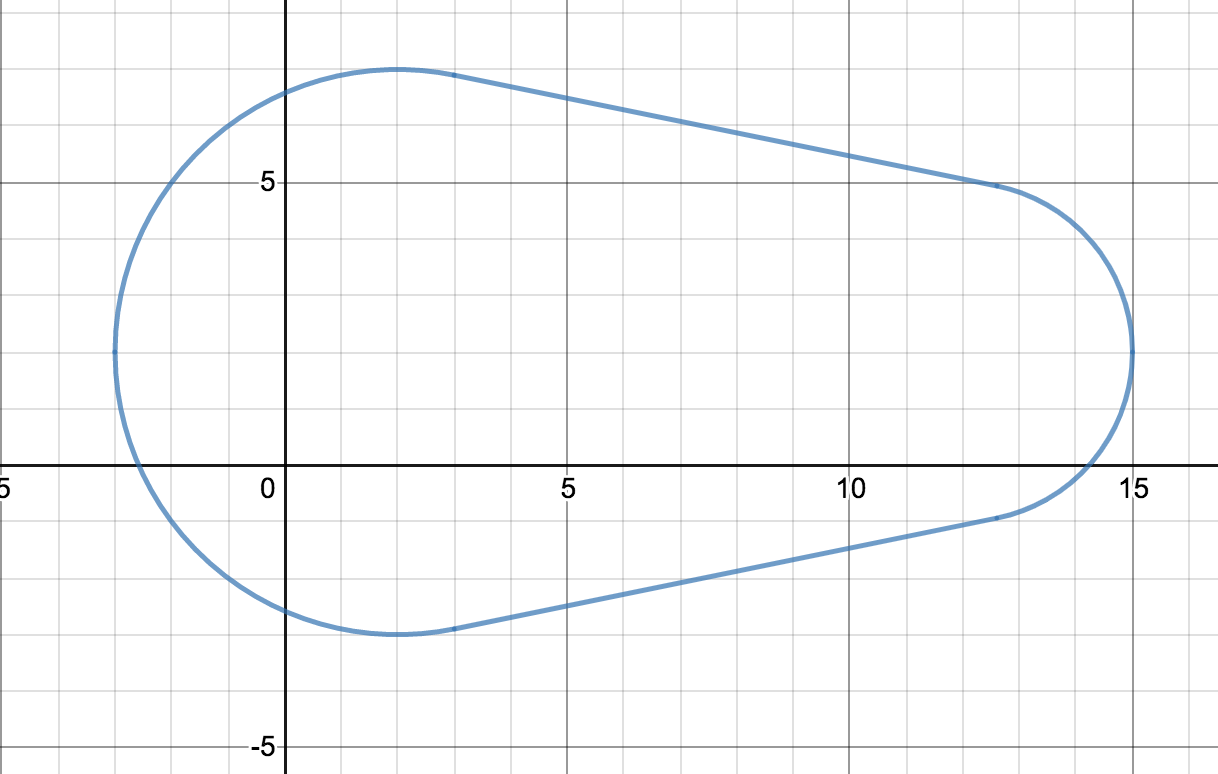
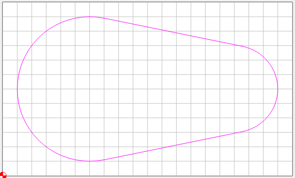
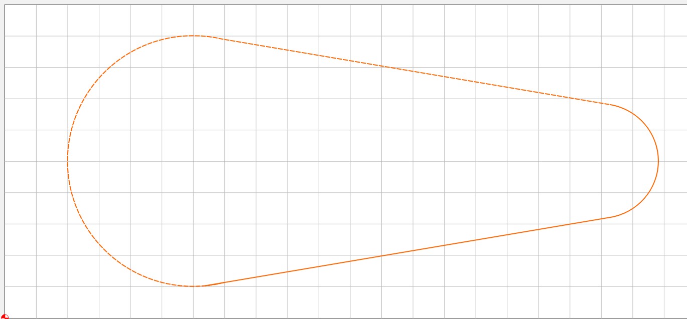
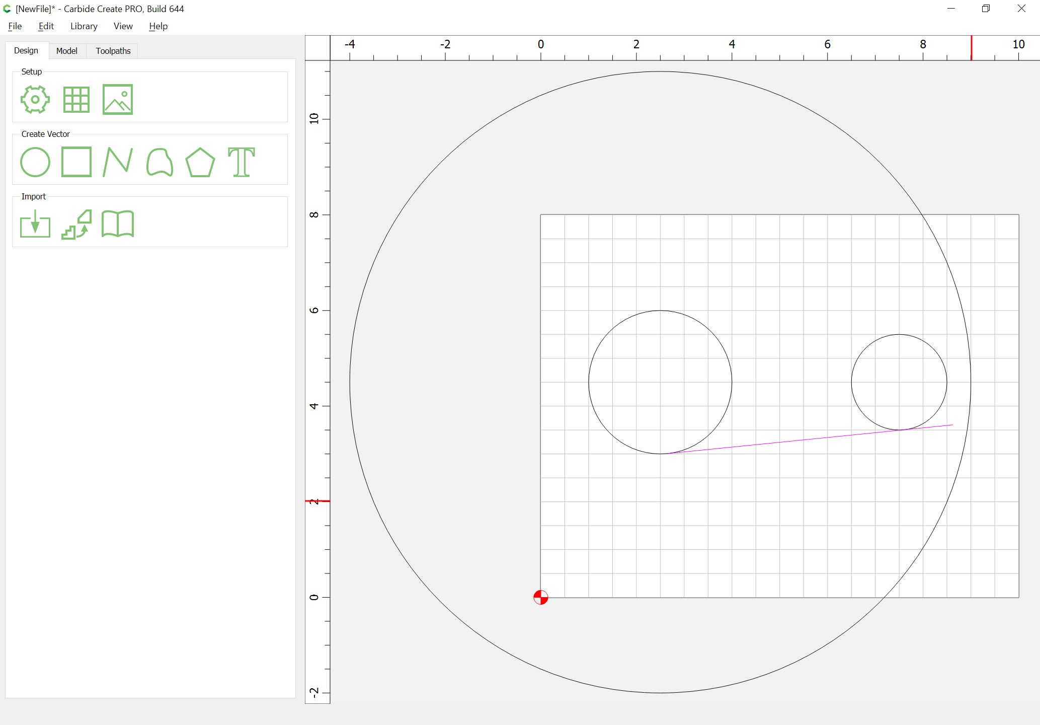
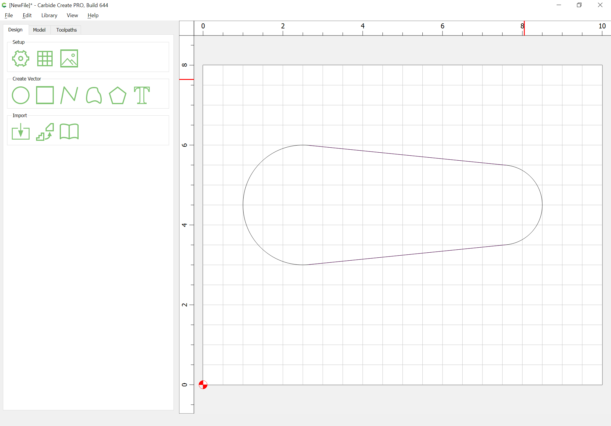
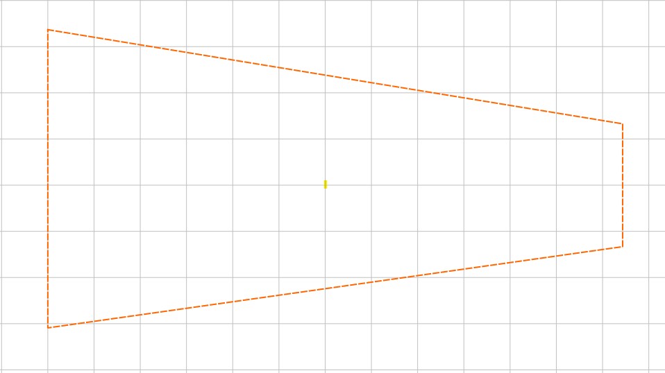
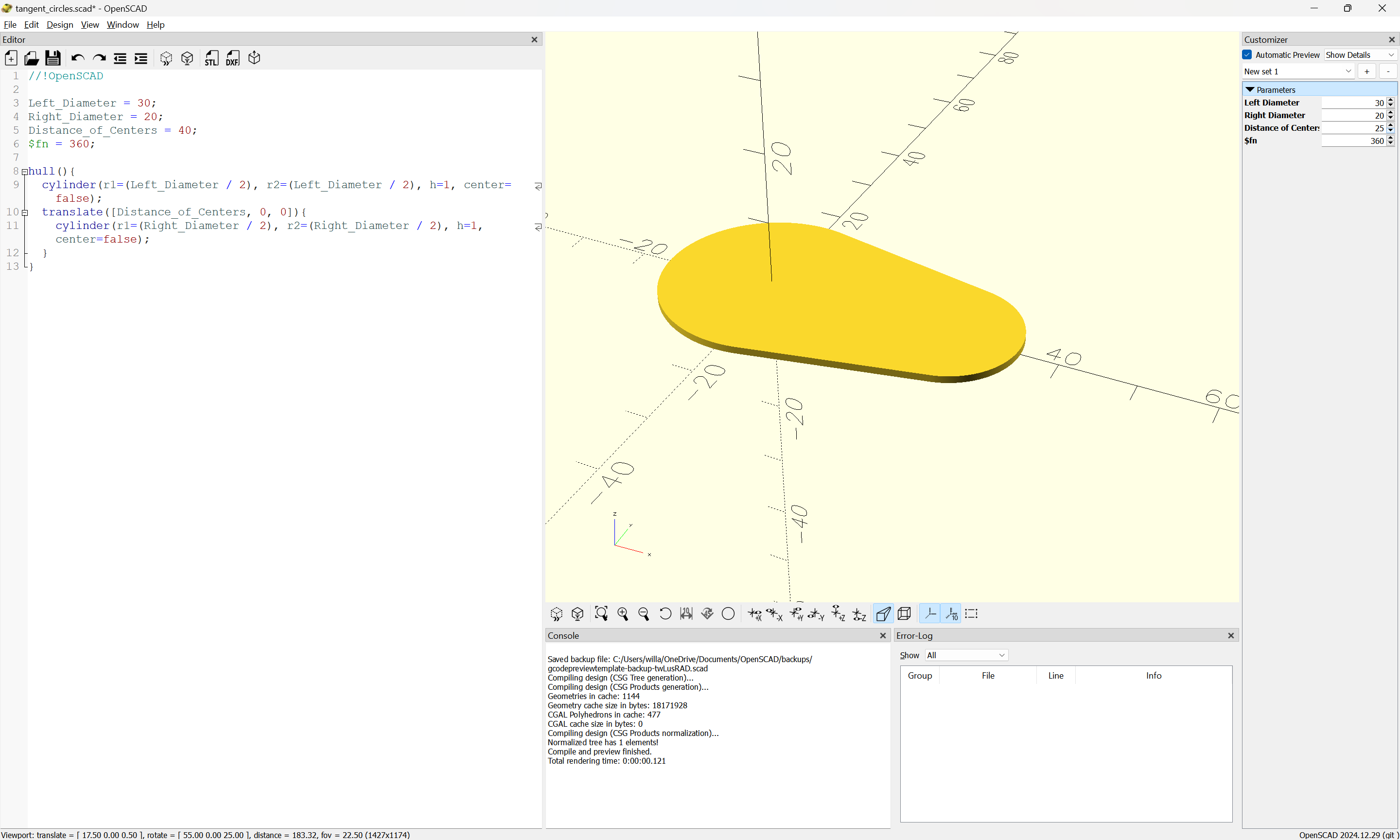
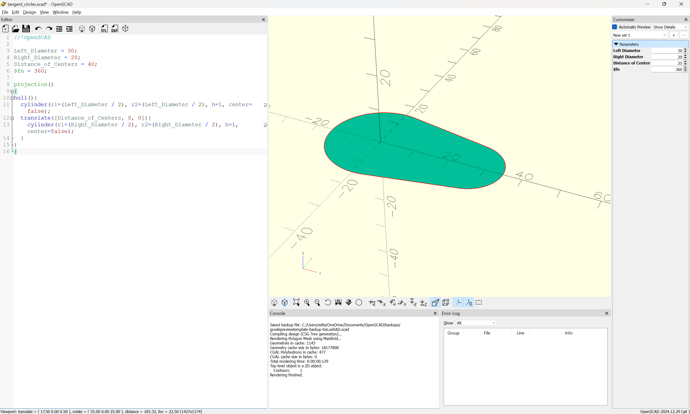
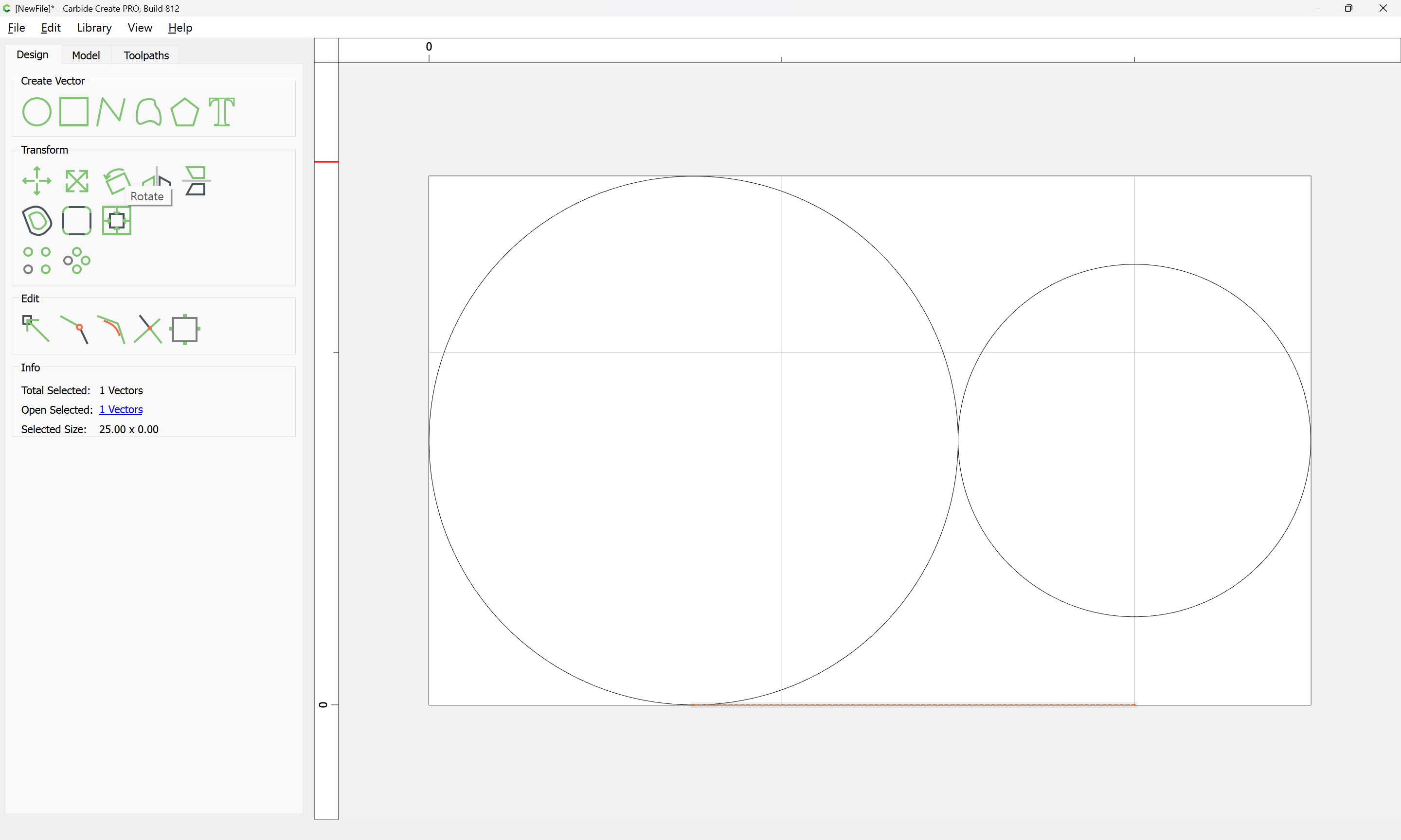
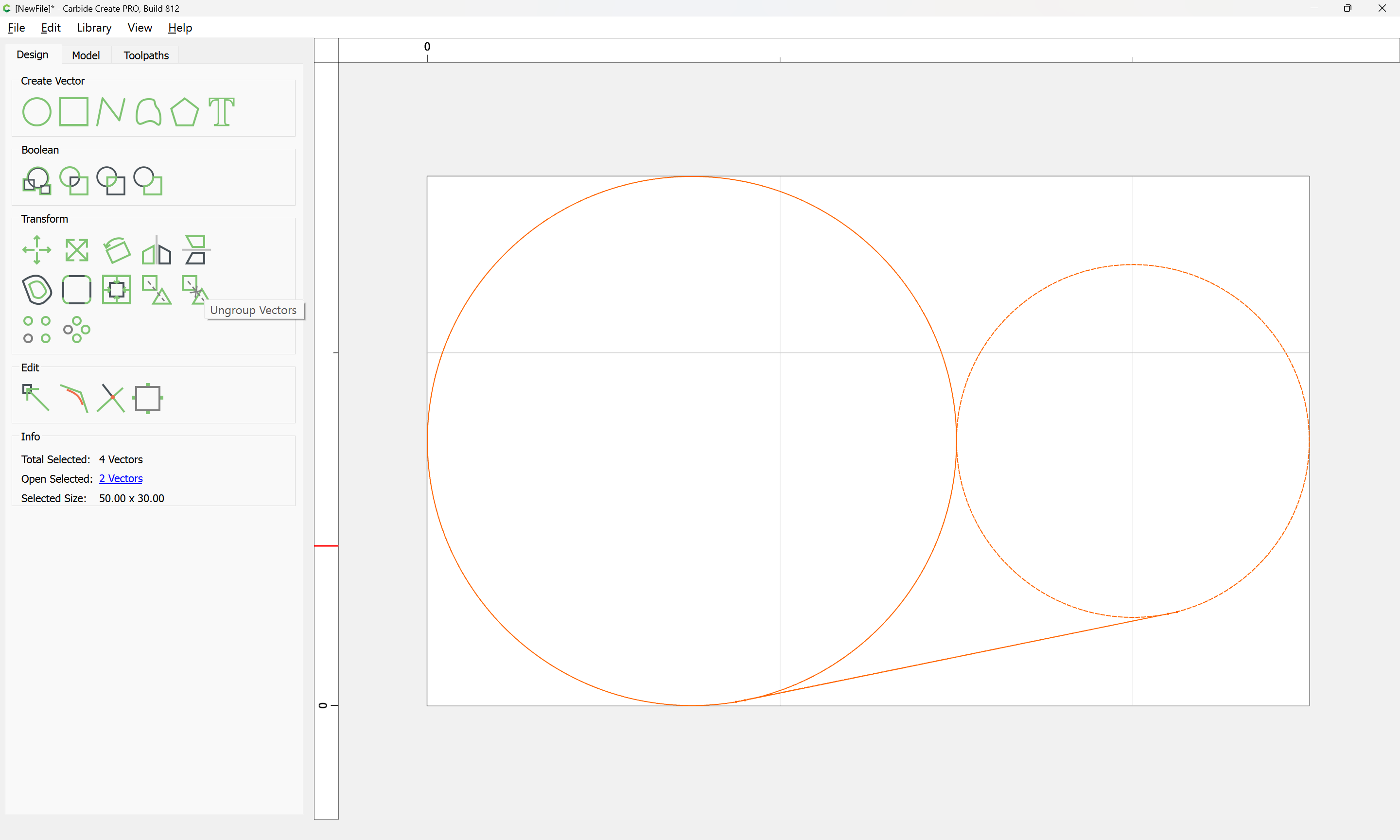
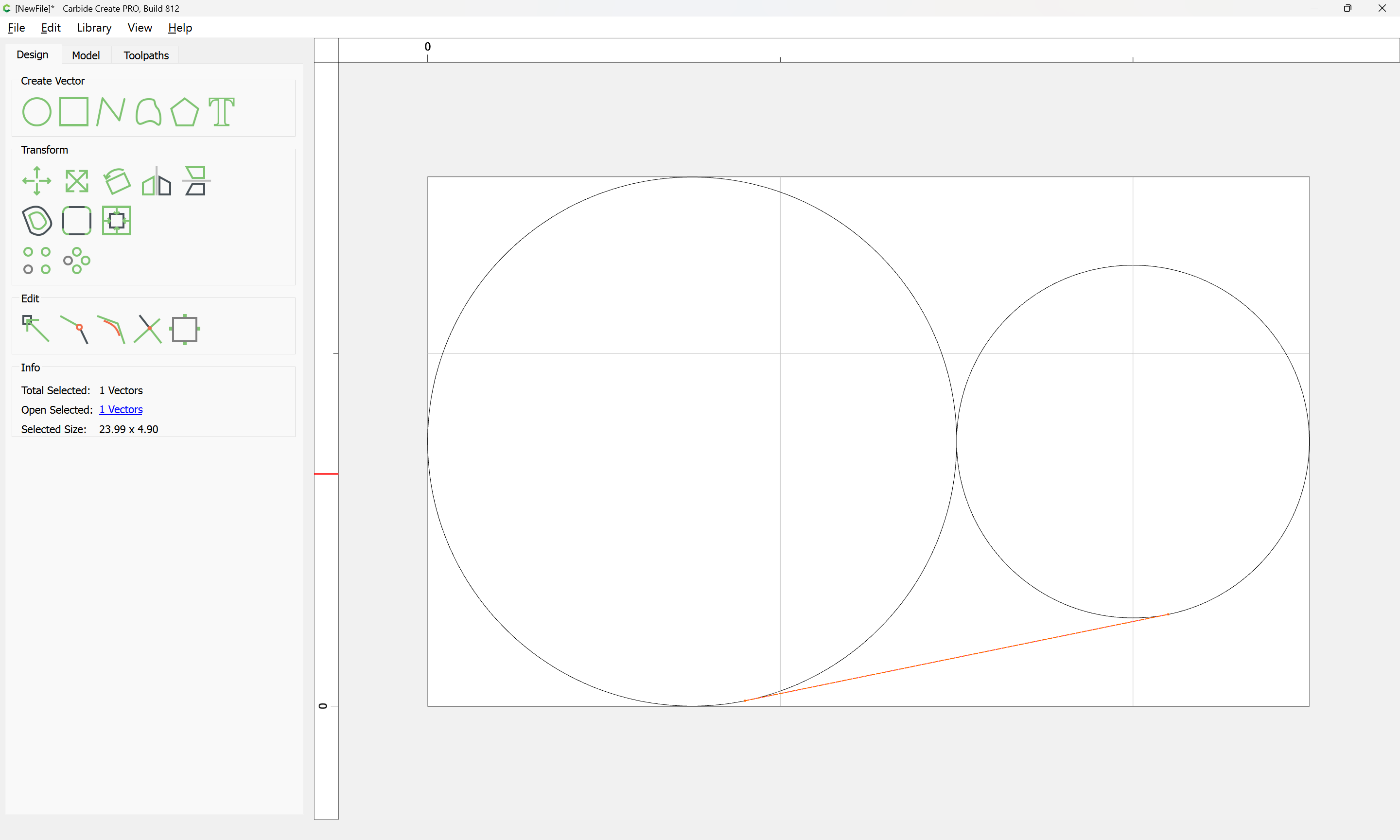
It is essentially the outer perimeter of two circles of different radii connected by tangent lines. I can easily create the circles, but haven’t come up with an efficient way to connect them with the tangent lines. Any assistance will be greatly appreciated.

Thanks,

Jim

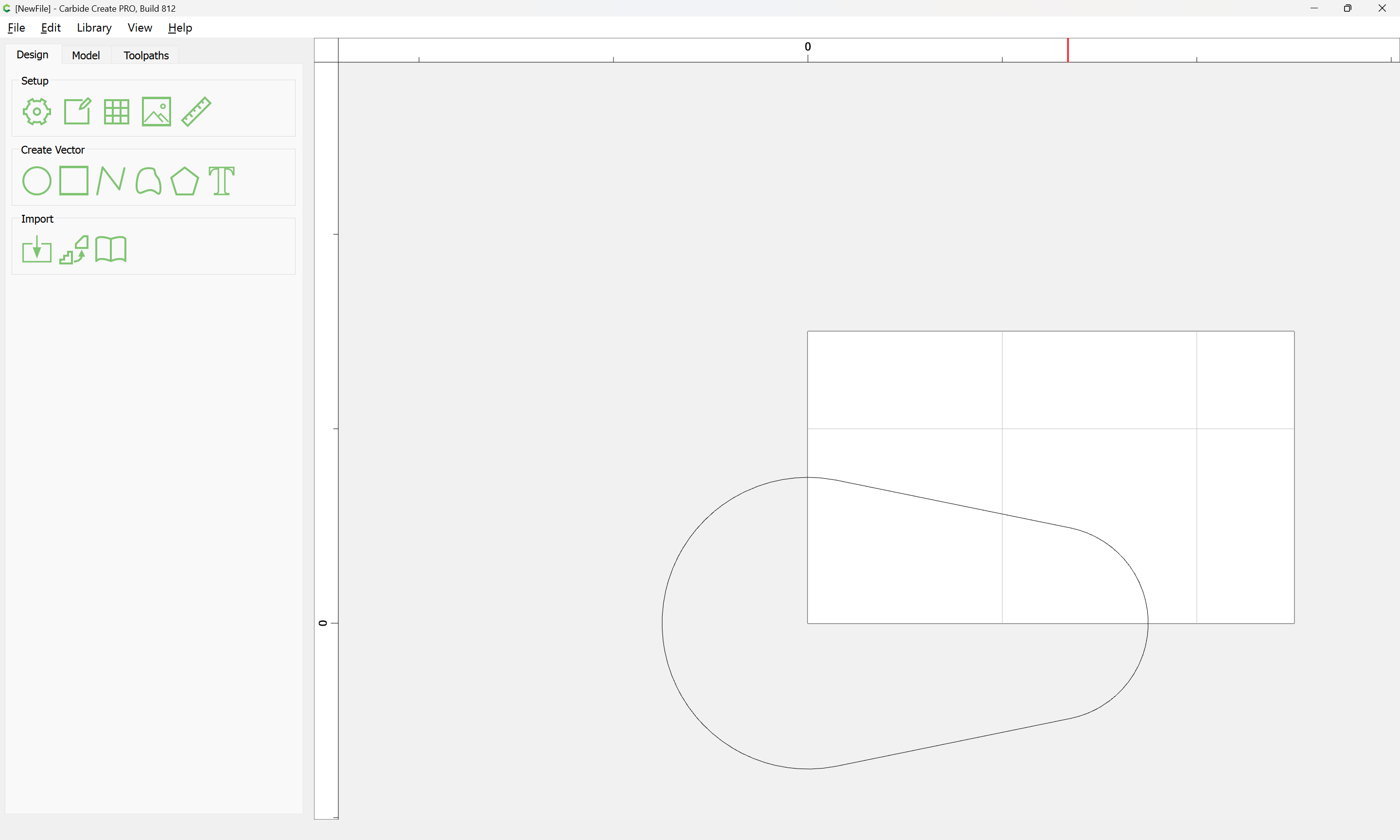
I created just a shape when I designed the pocket for a wrench.
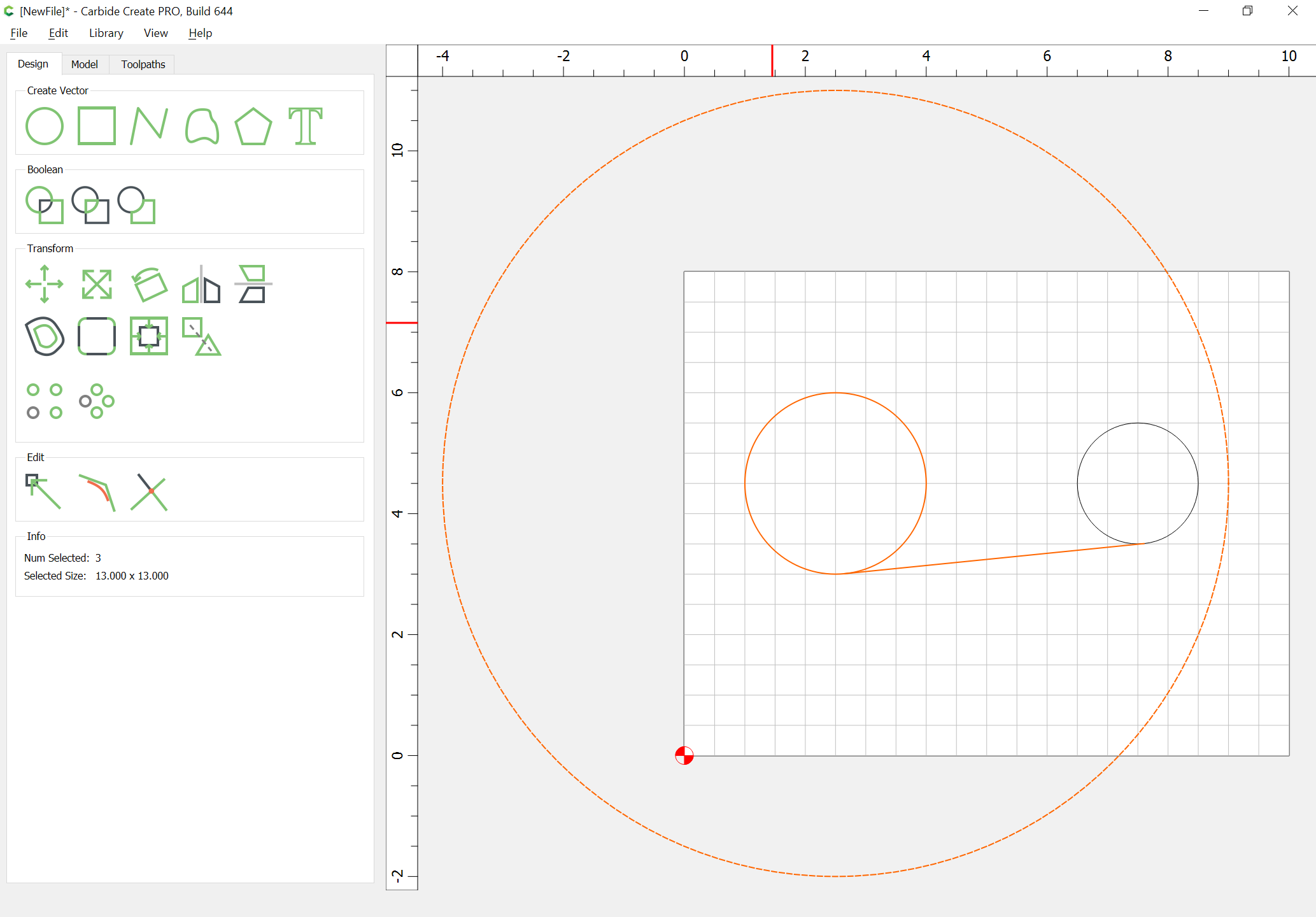
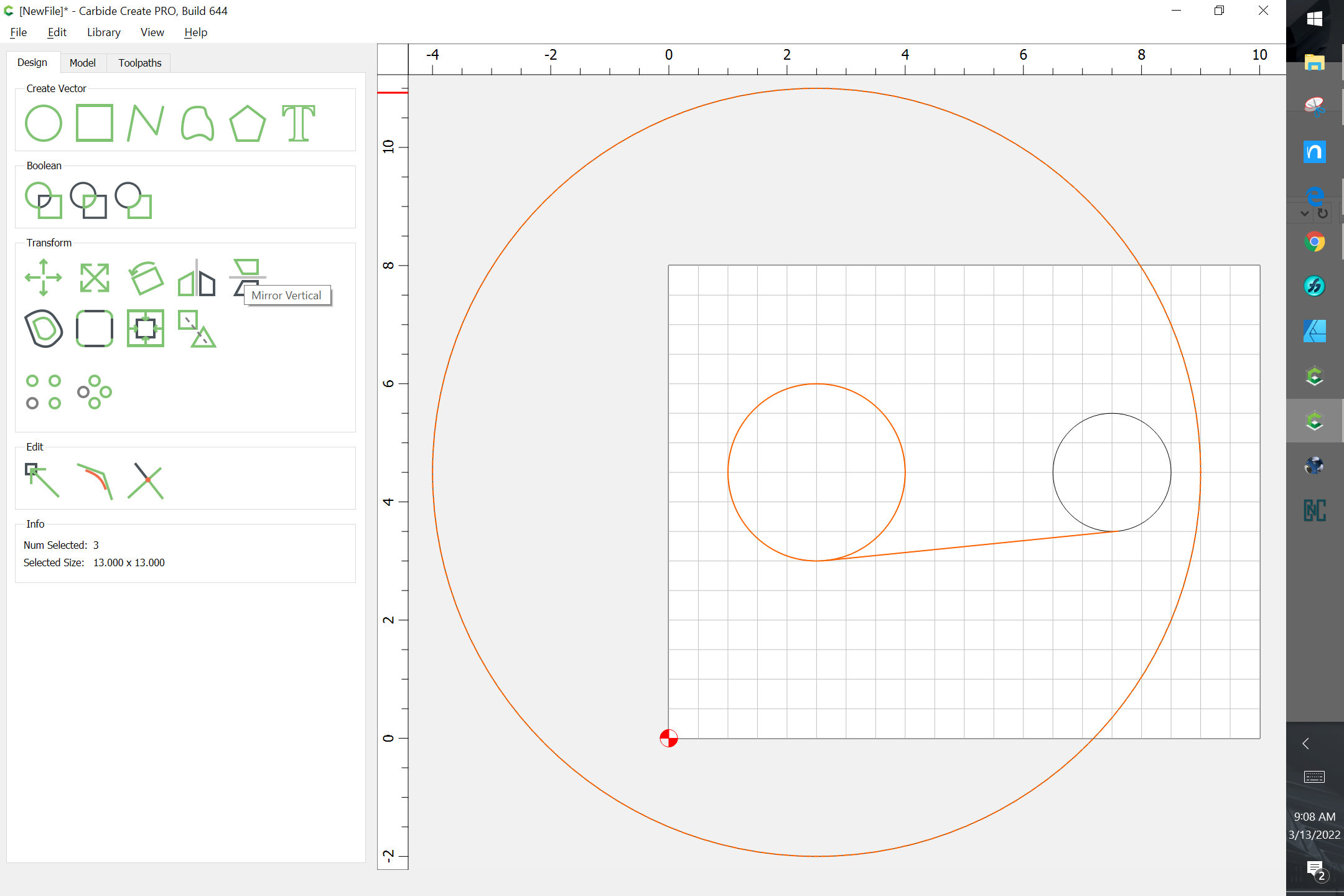
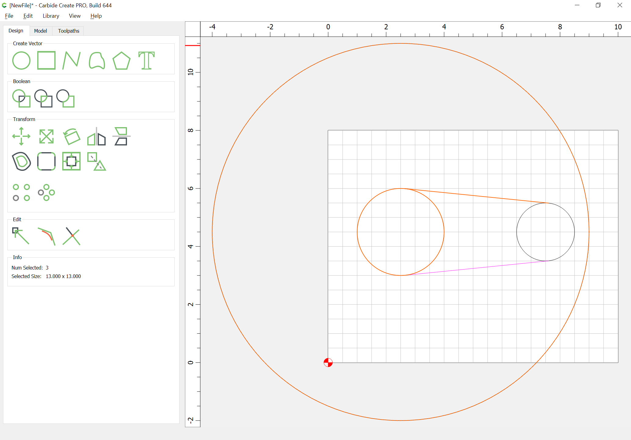
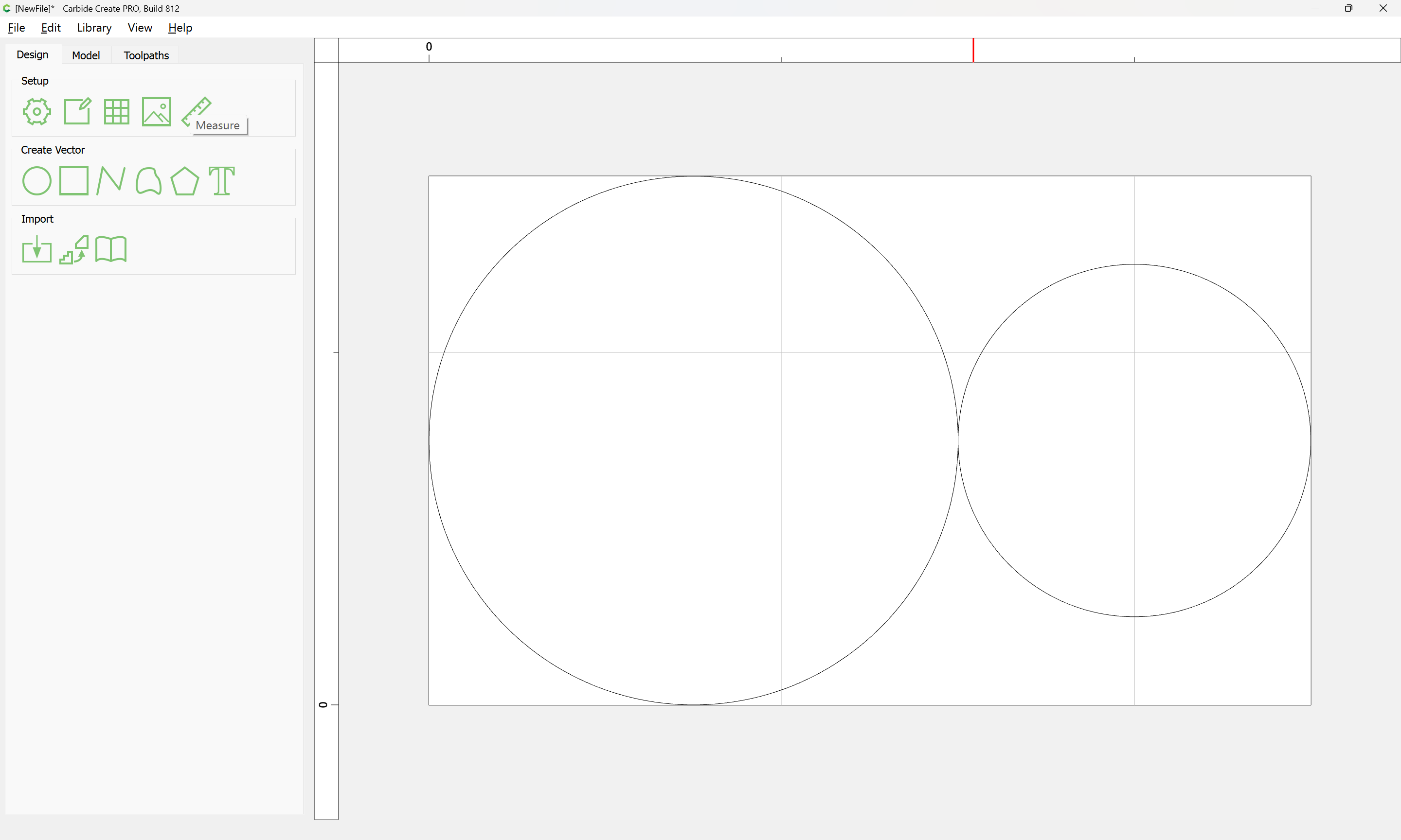
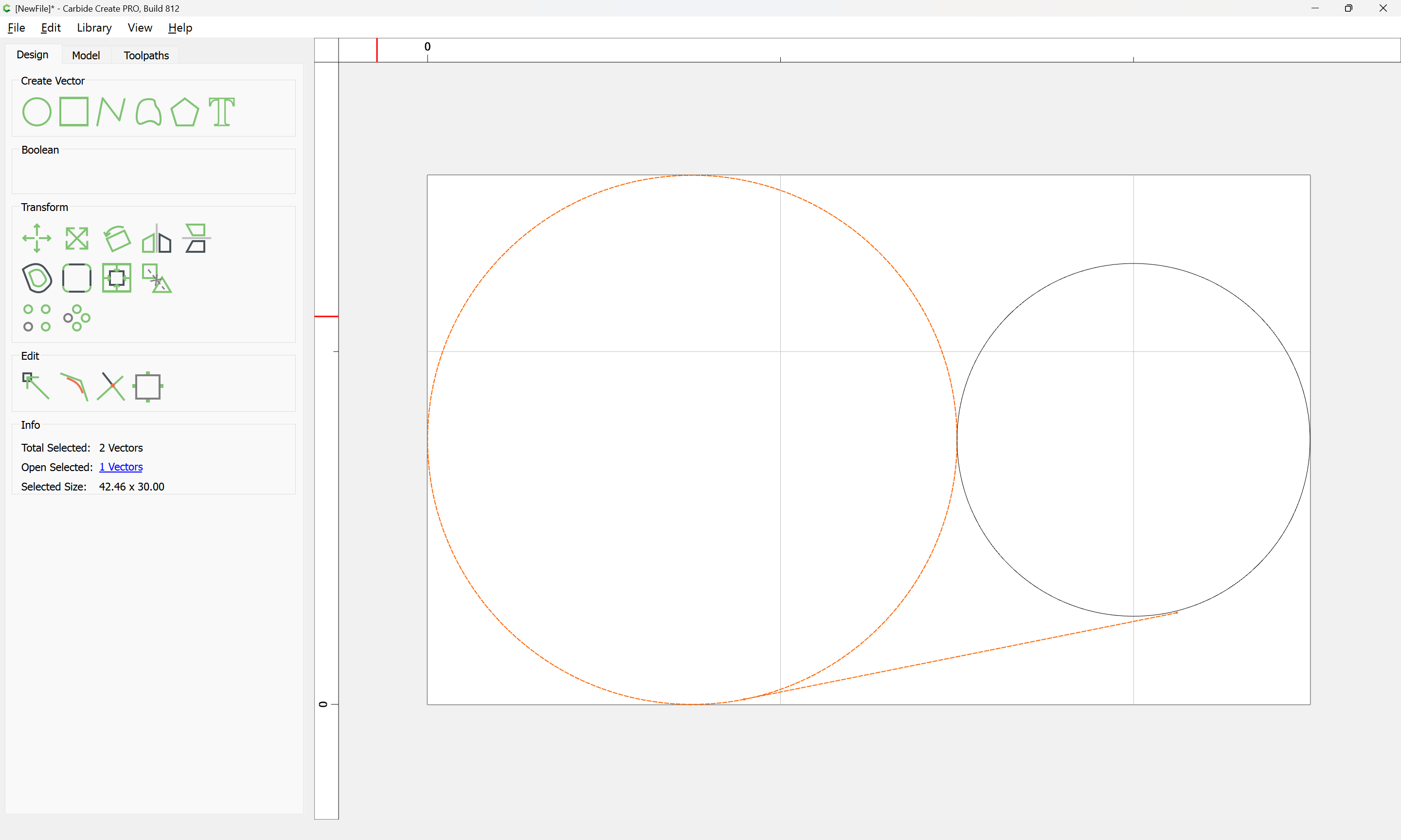
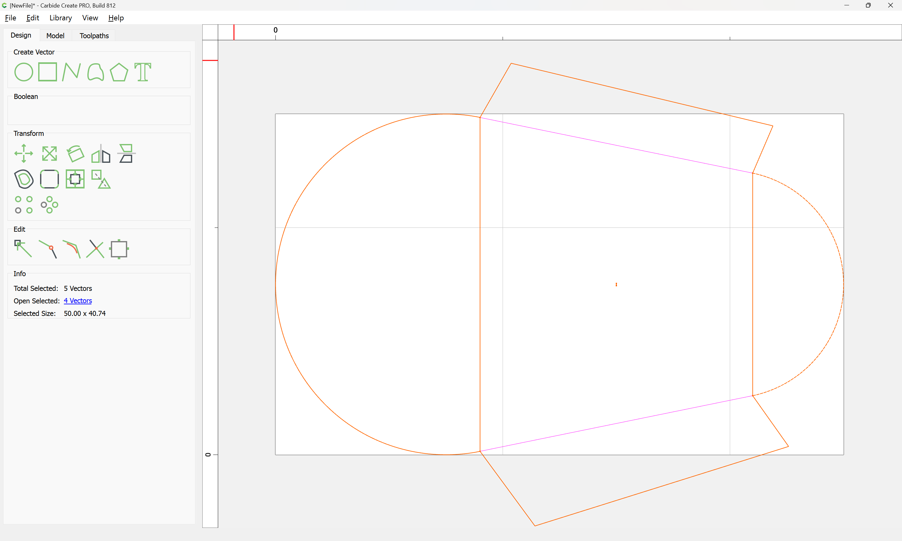
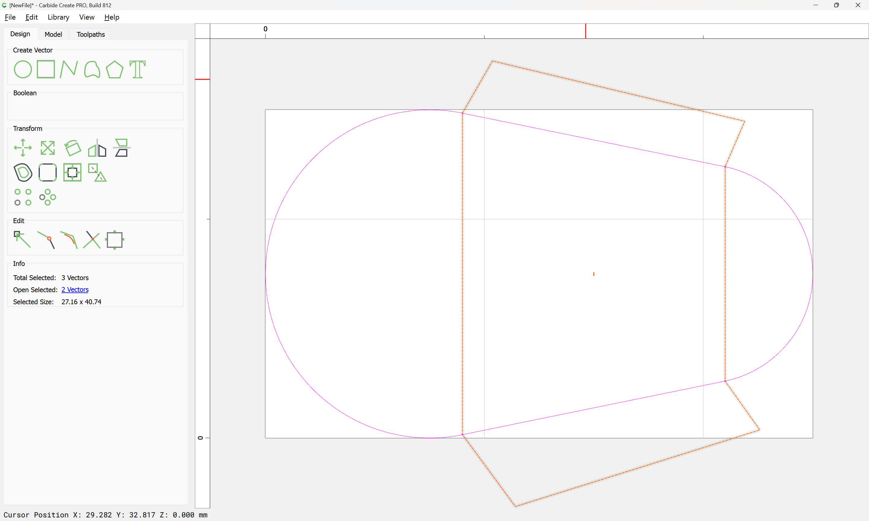
I made the circles for each end and connected them with lines on top and bottom. Then used Boolean to save the outer shape as one.

You would need to do the trigonometry to determine the tangents, or the necessary rotation.

I worked up an example of doing this in BlockSCAD here:

the file could be exported to OpenSCAD and a projection() command added to get a flat version which can be exported to a DXF or SVG.

Alternately, program in a tool such as Nodebox and export an SVG?

Start with your 2 circles

image

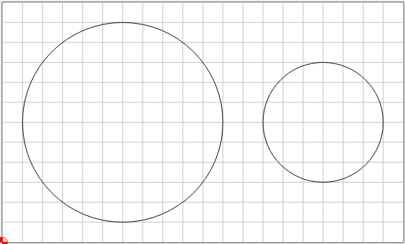
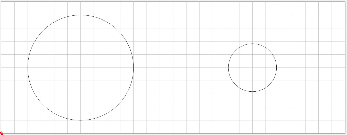
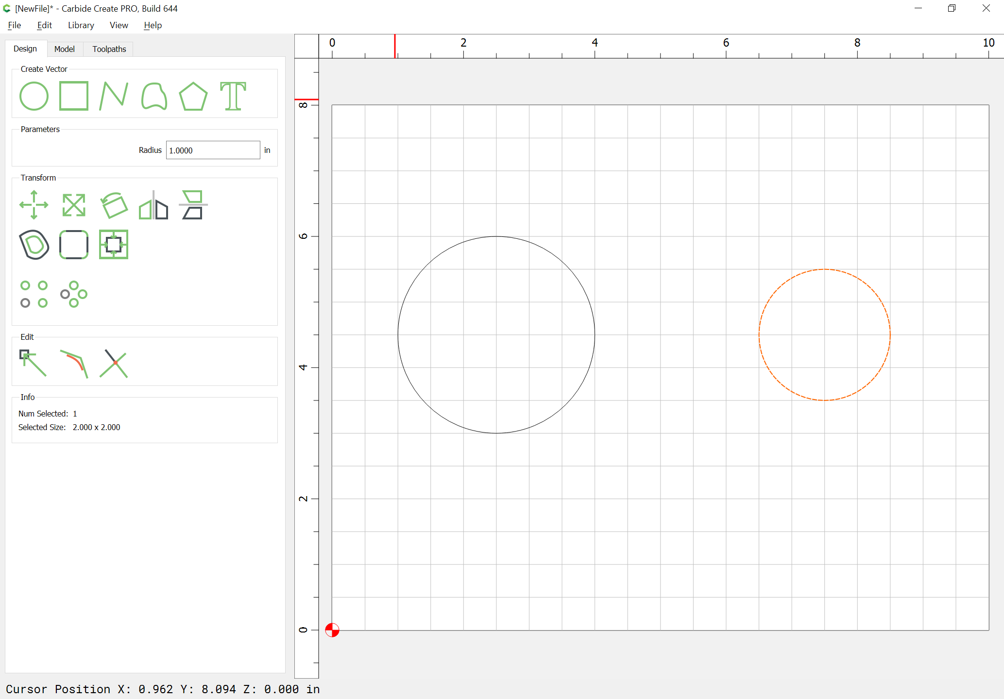
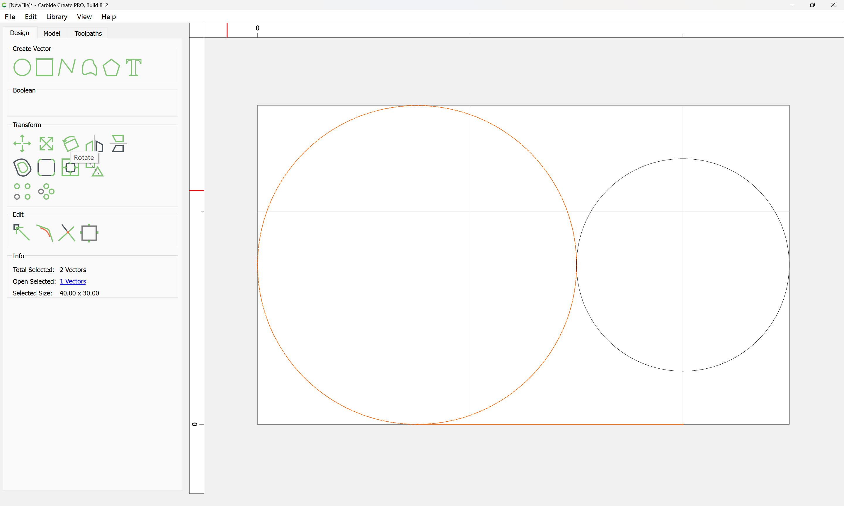
Create a ratio from the difference between the radii, and the distance between centers. (2:10)
2:10 = 1:5, so I’ll use that

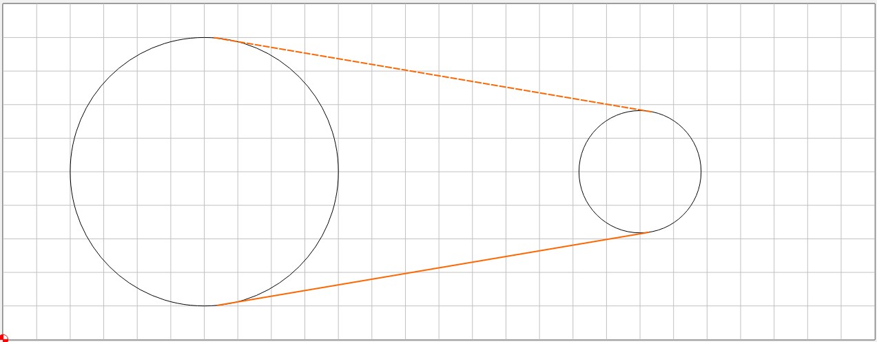
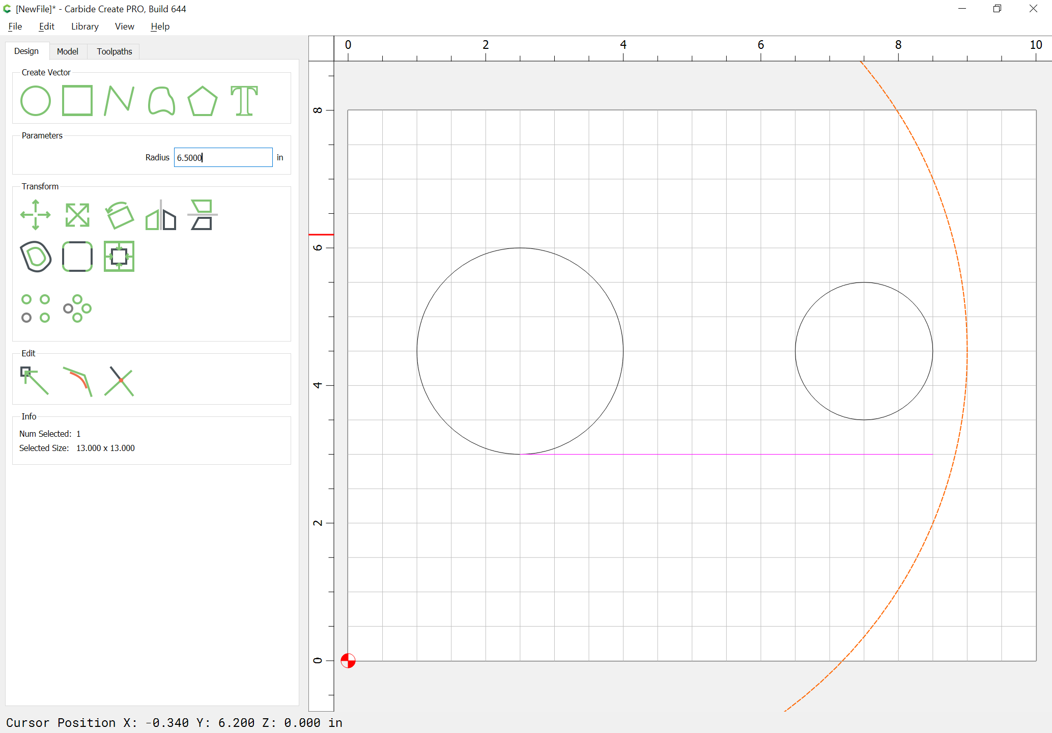
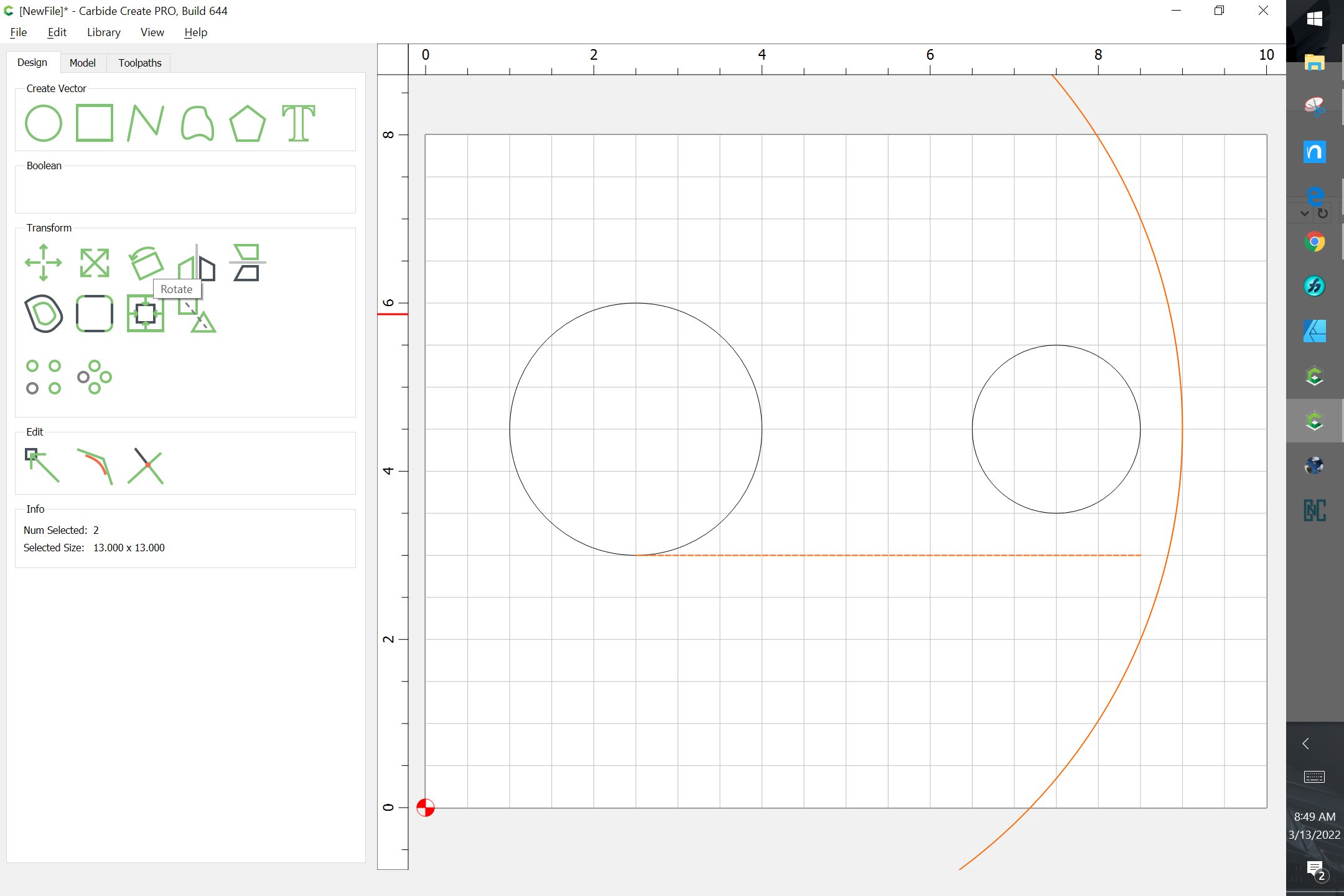
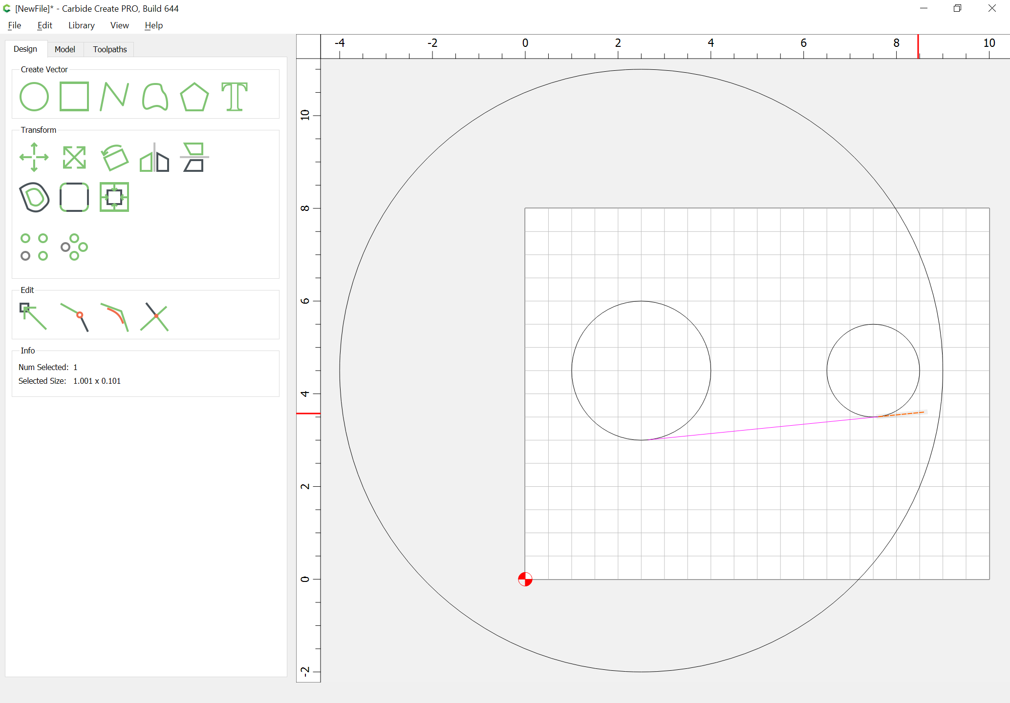
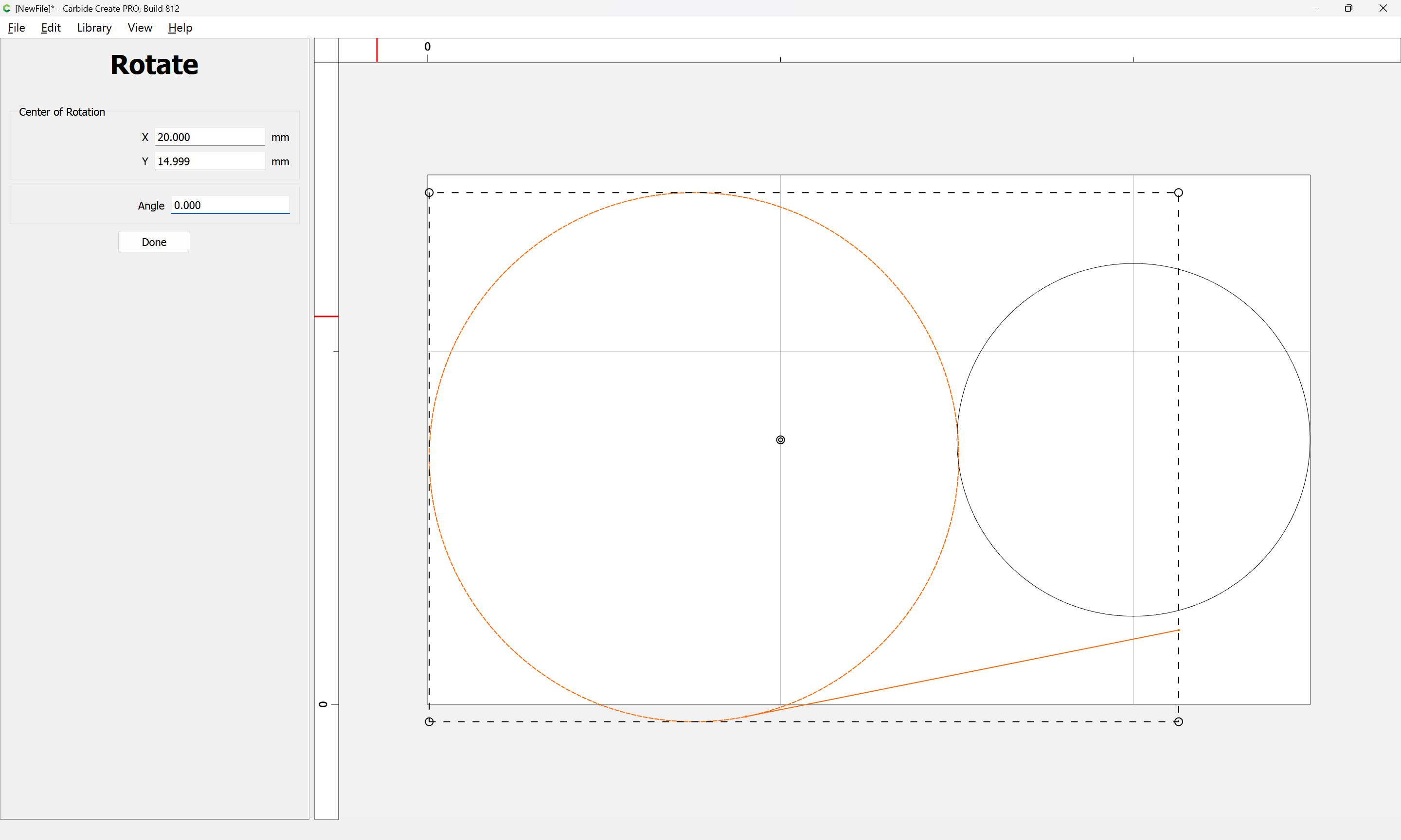
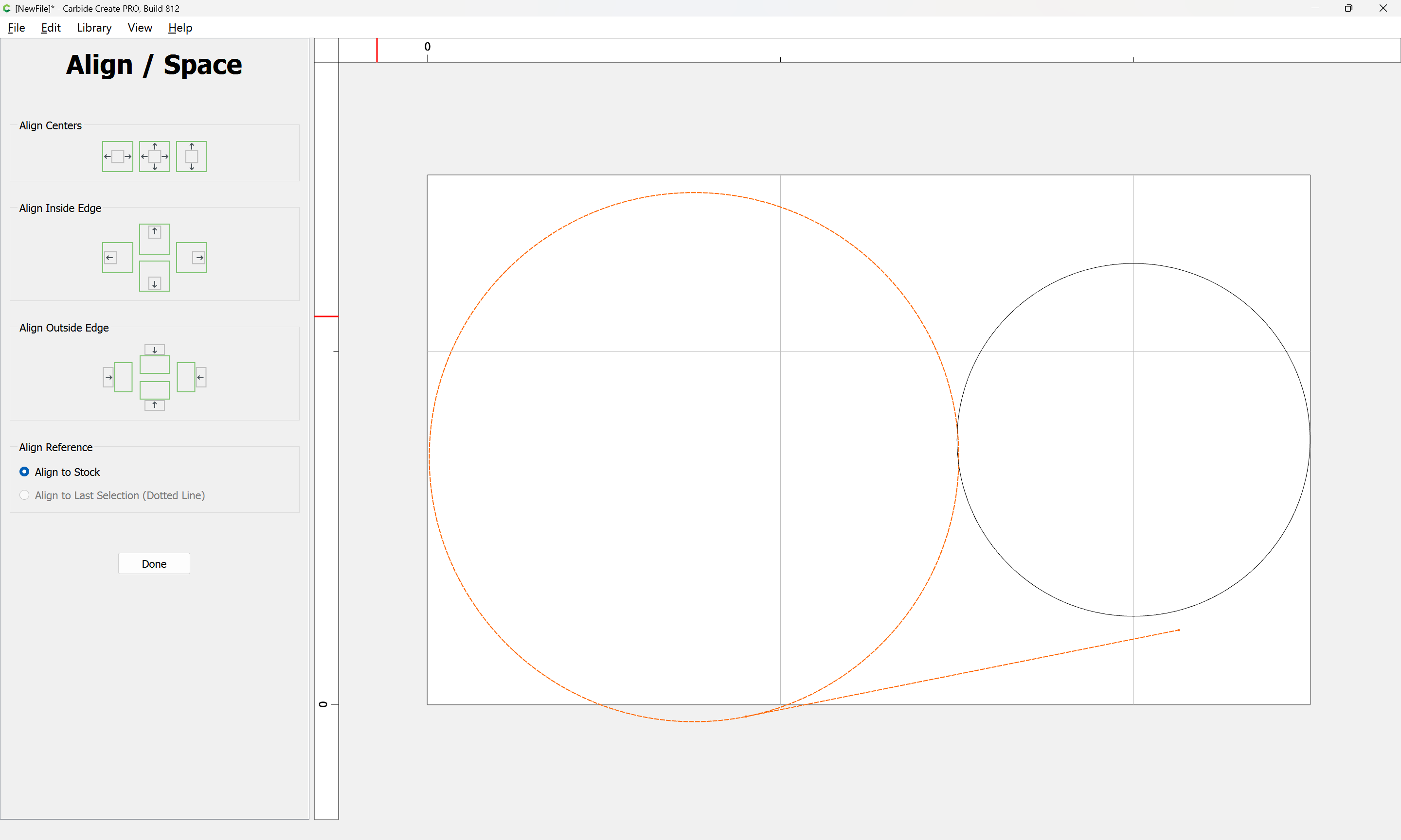
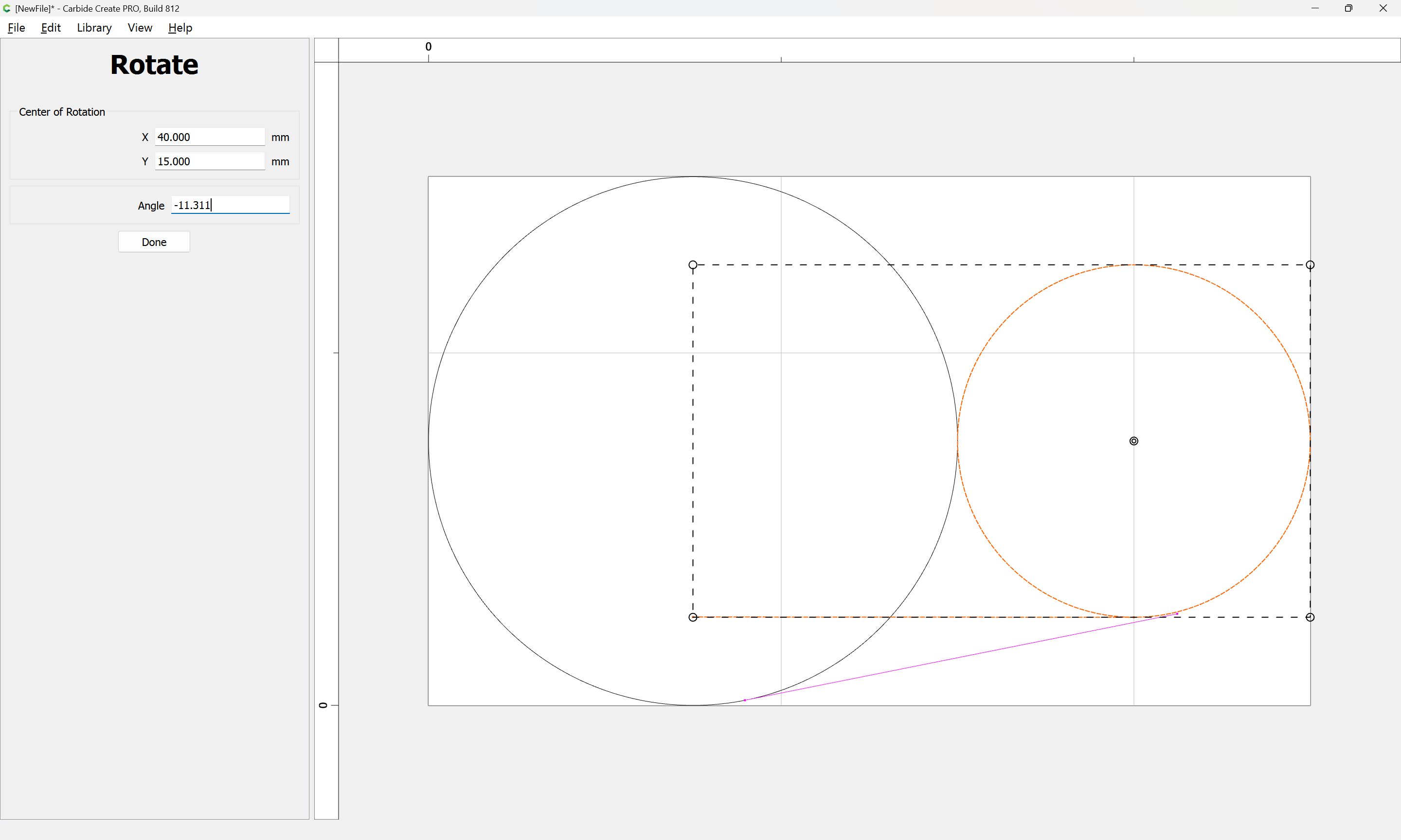
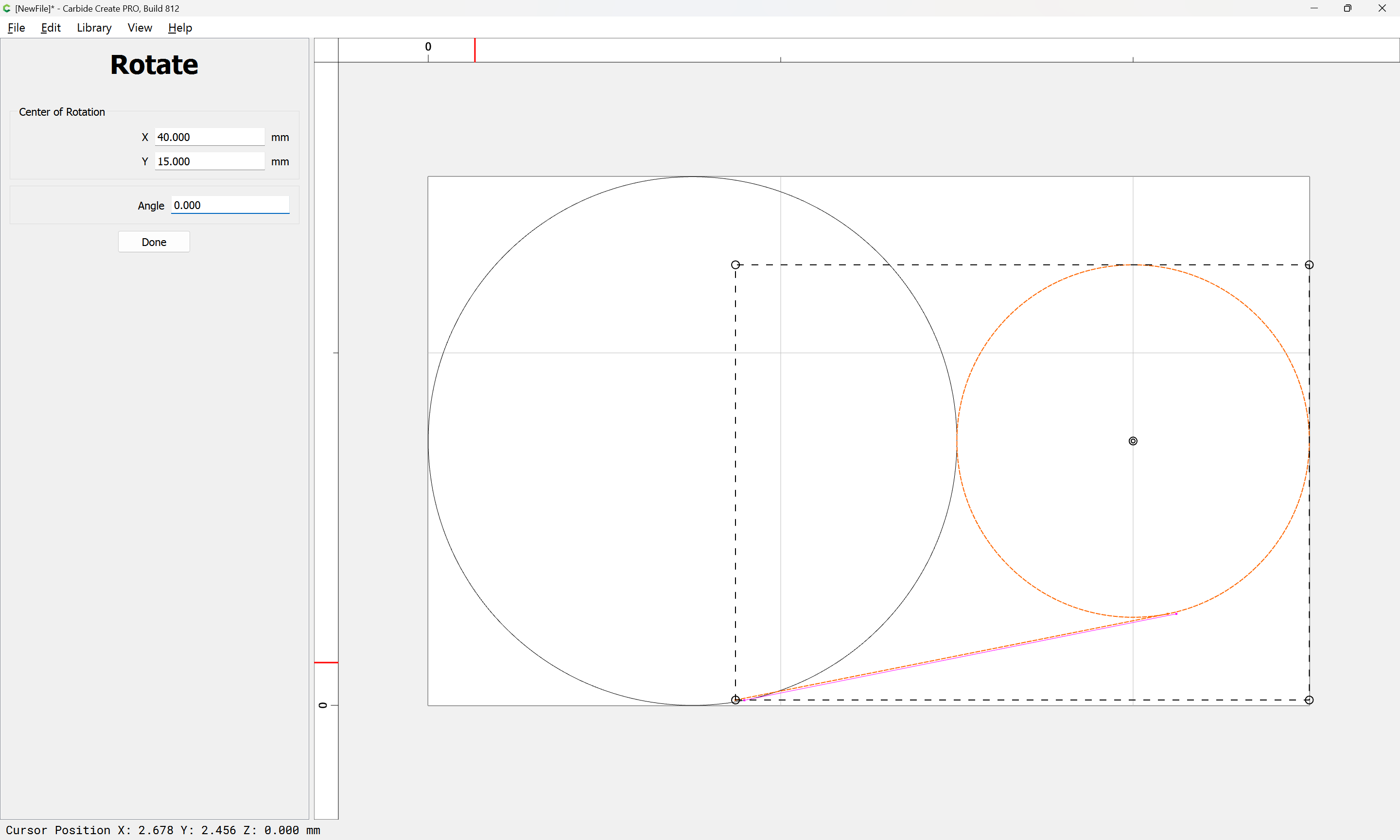
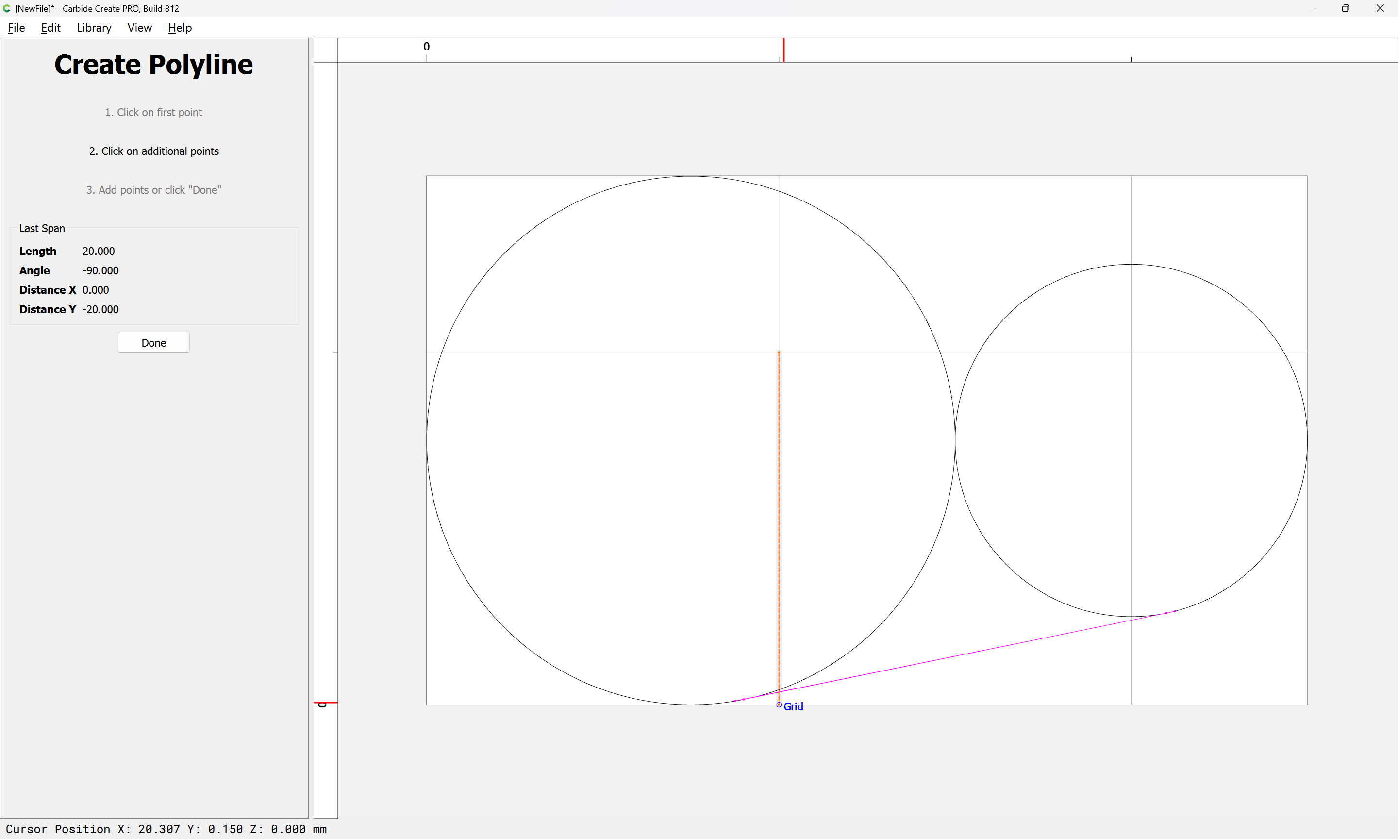
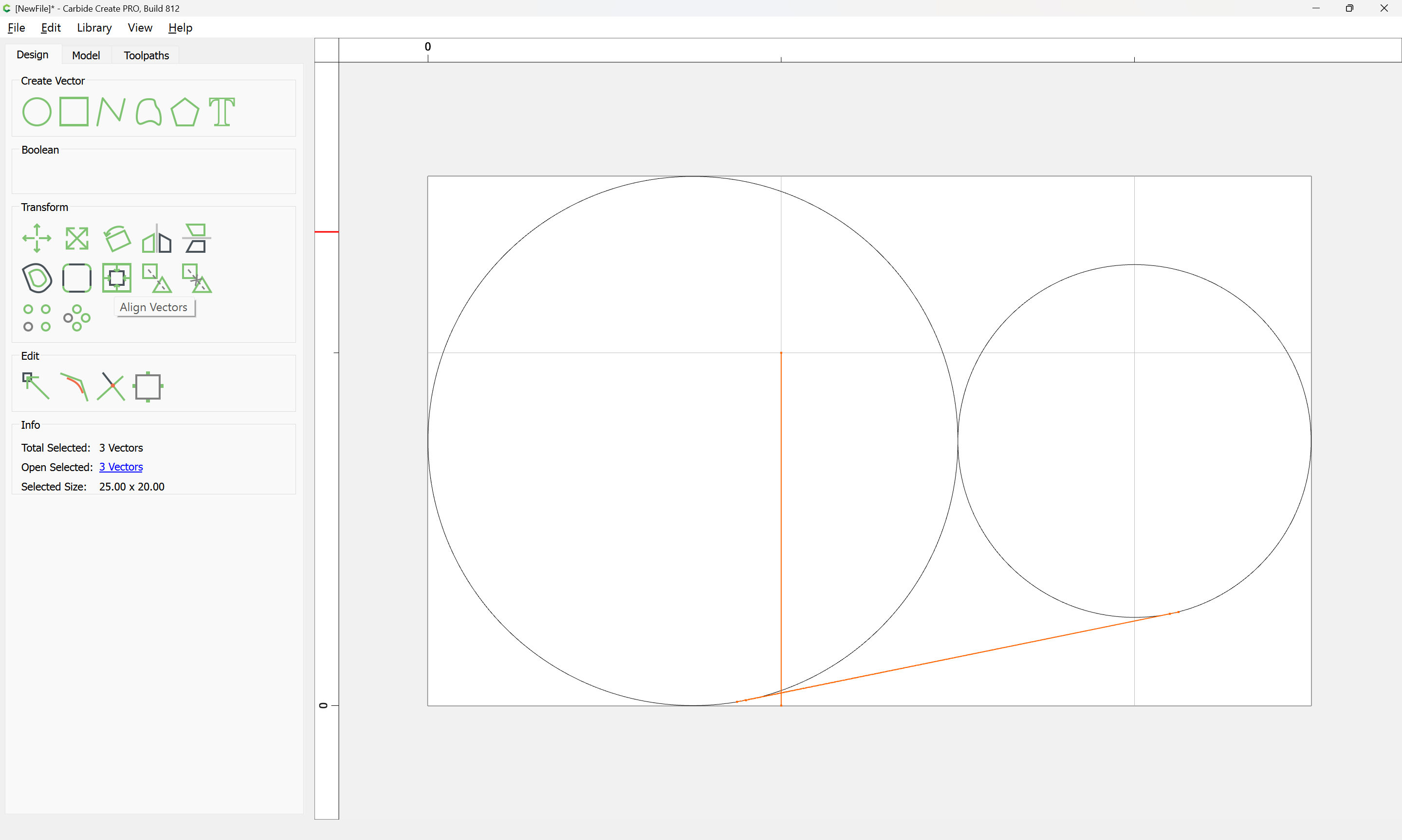
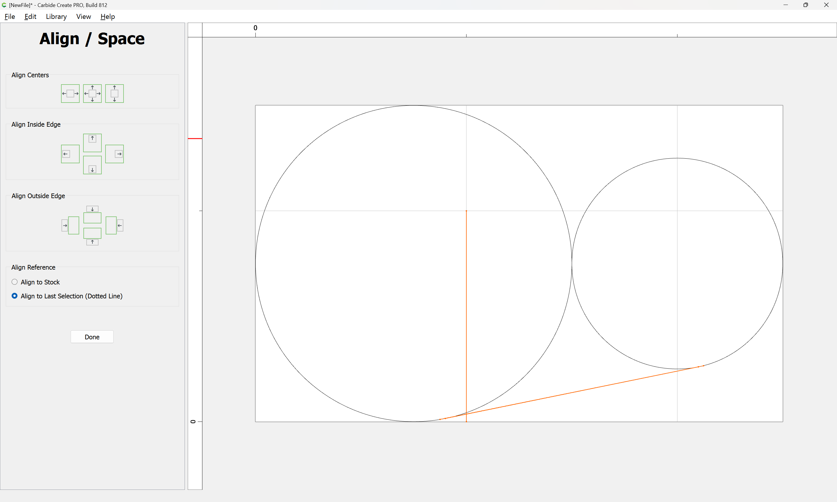
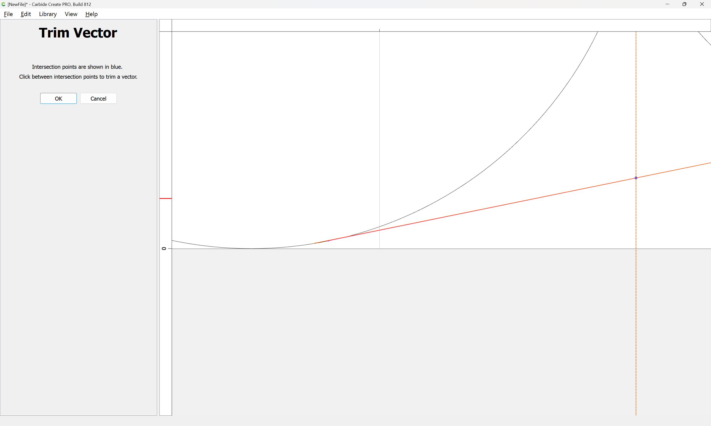
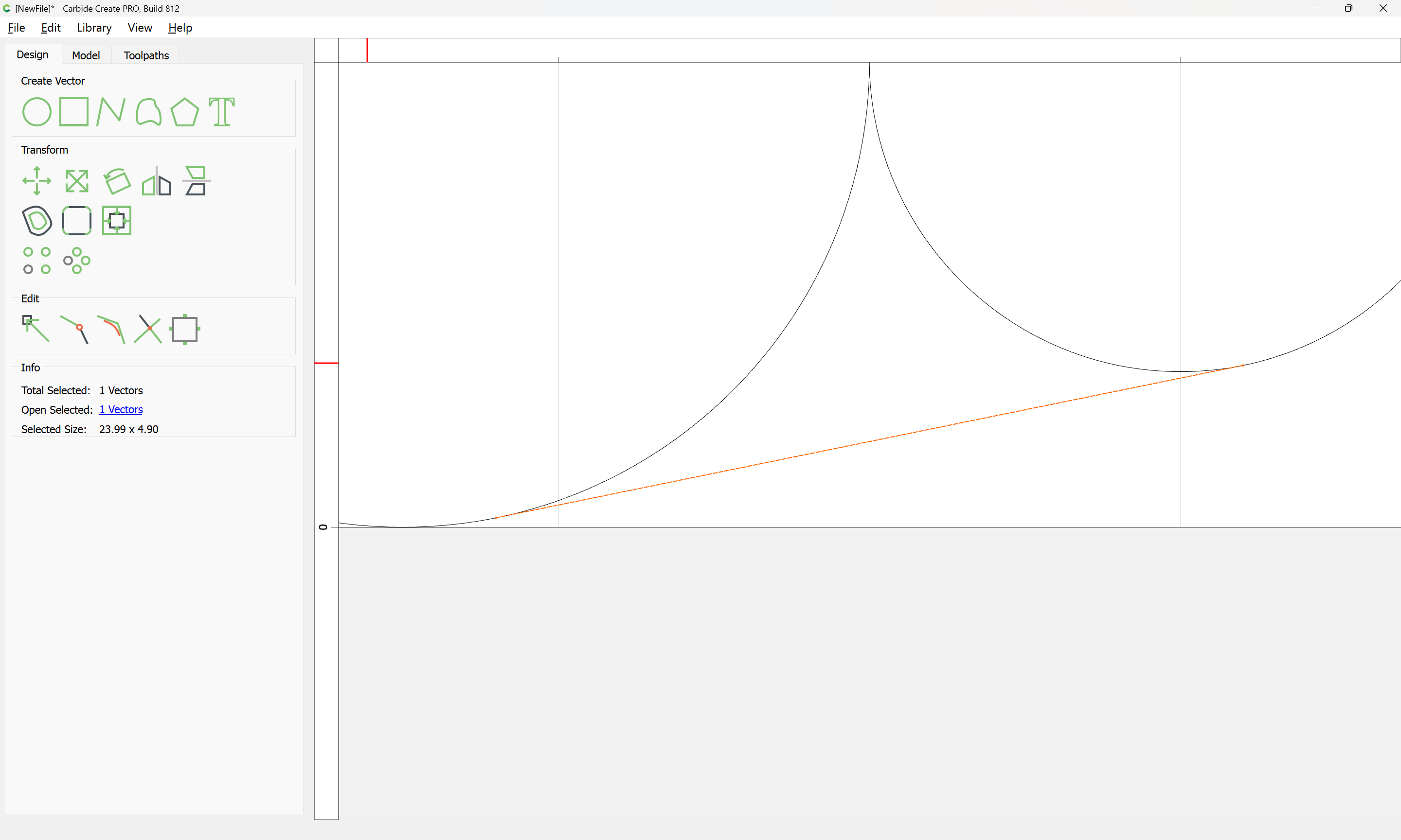
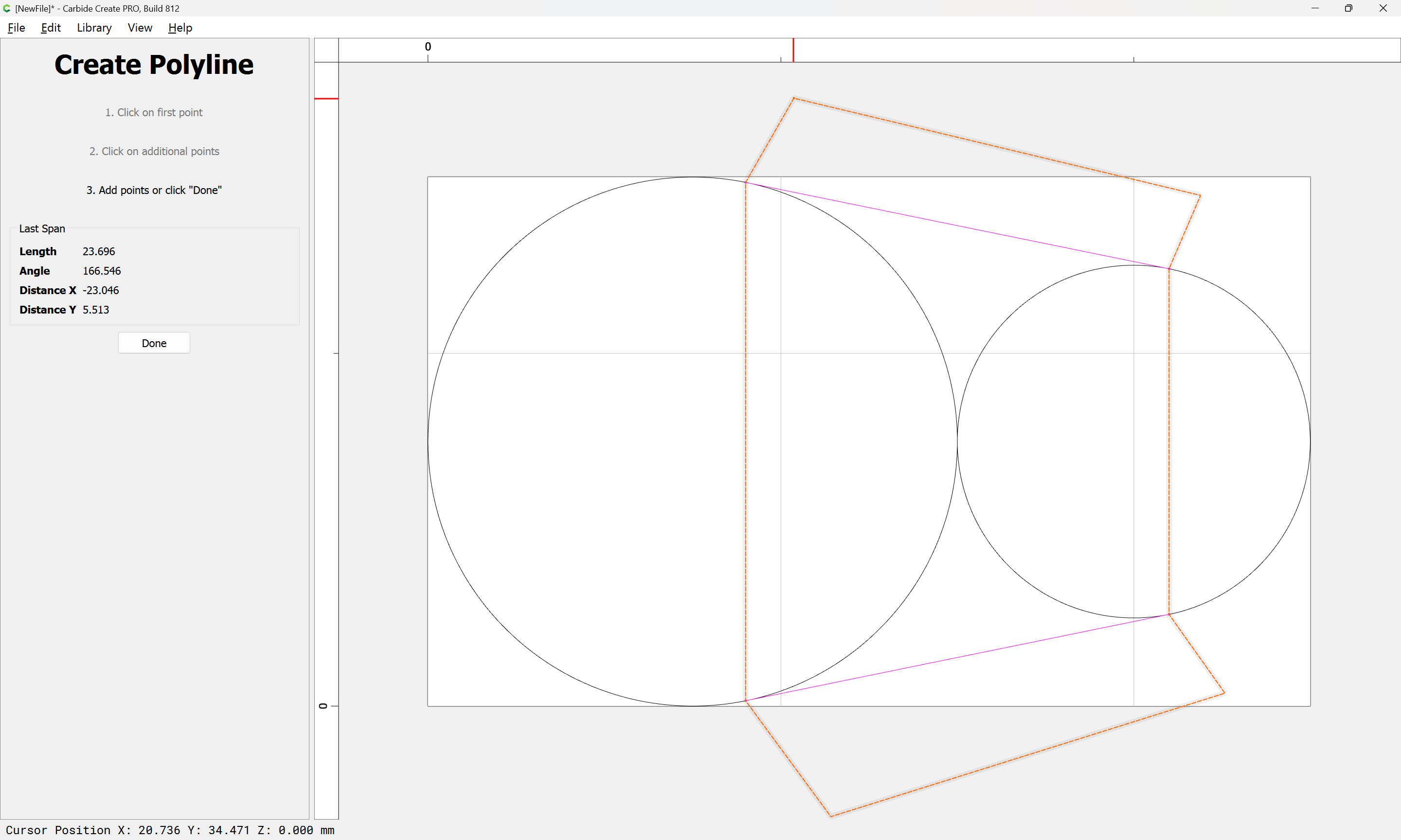
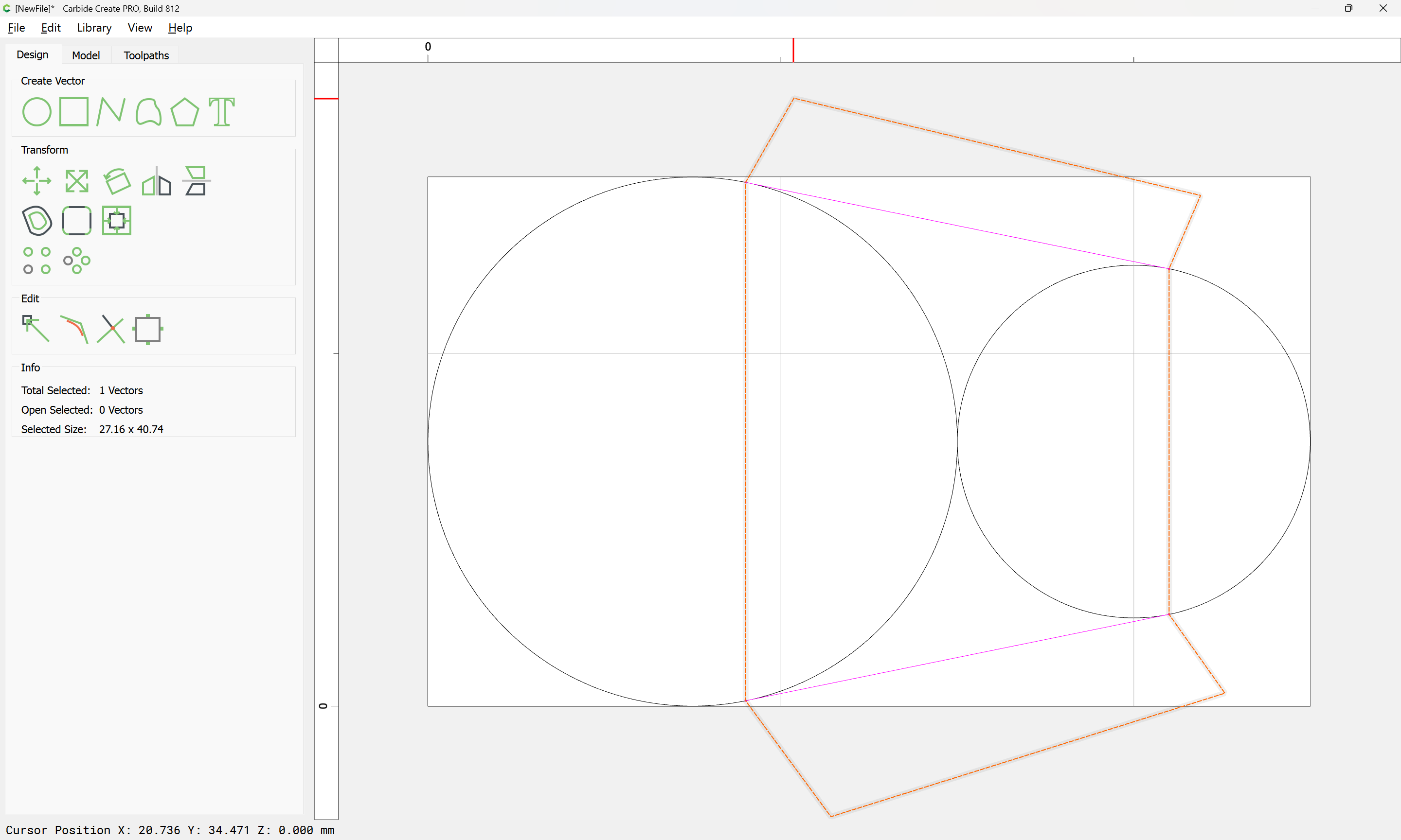
Create a line from the center of an arc, to a point 1 unit right, and 5 units up. Also 1 right, 5 down. On both circles. This is your tangent point.

image

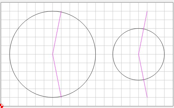
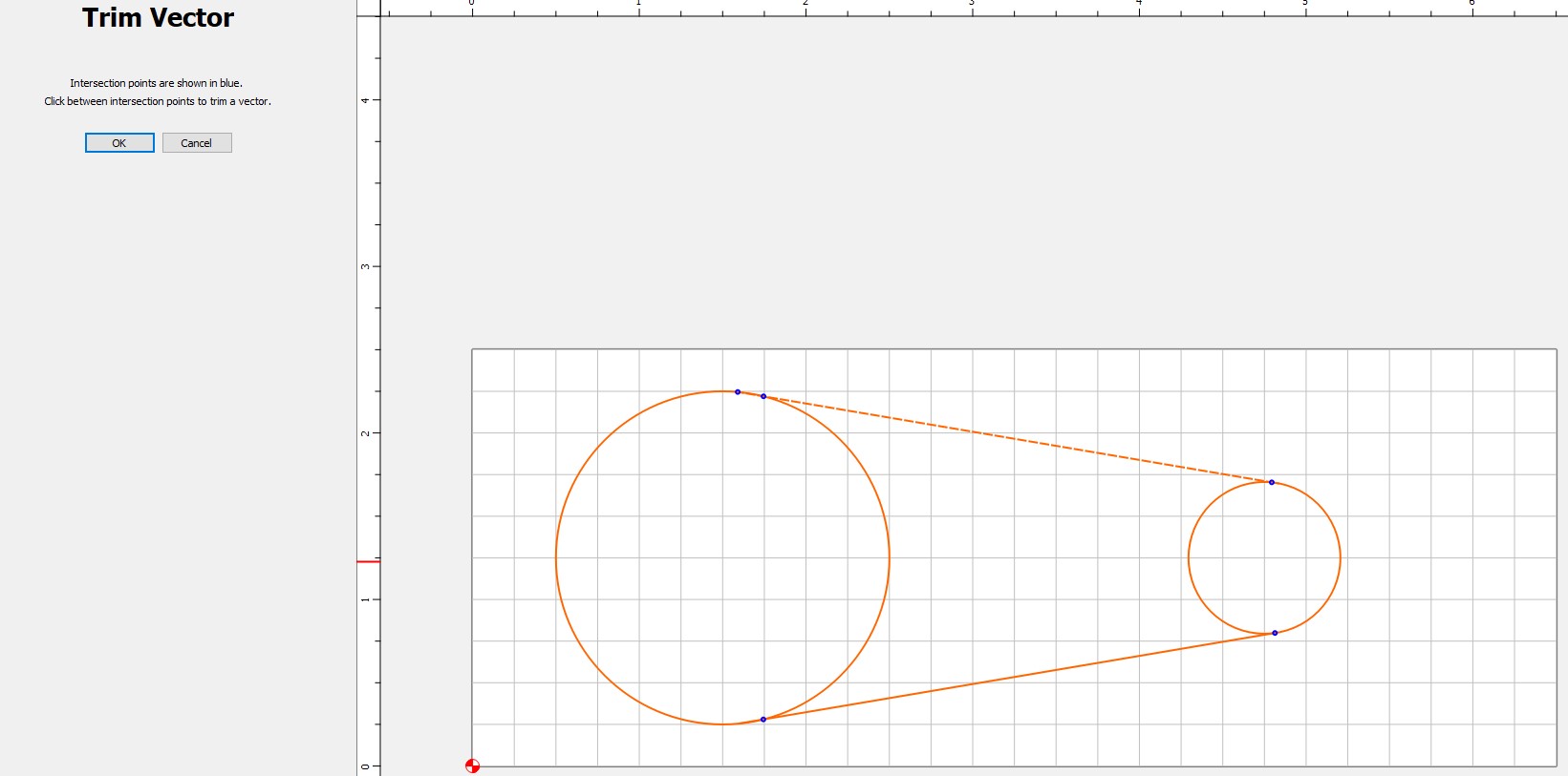
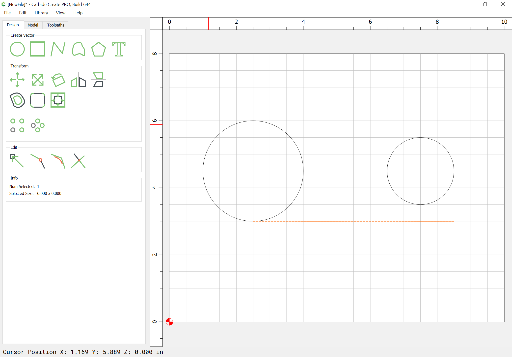
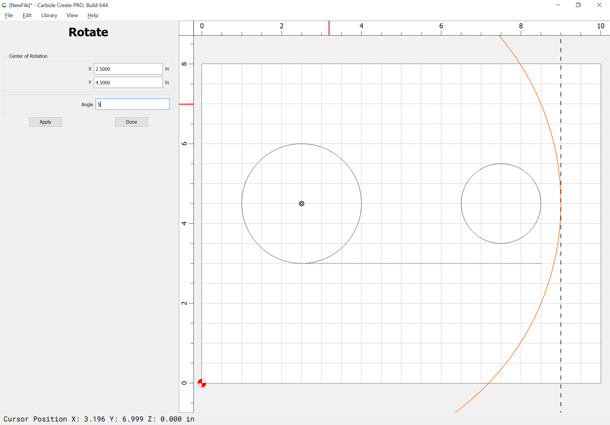
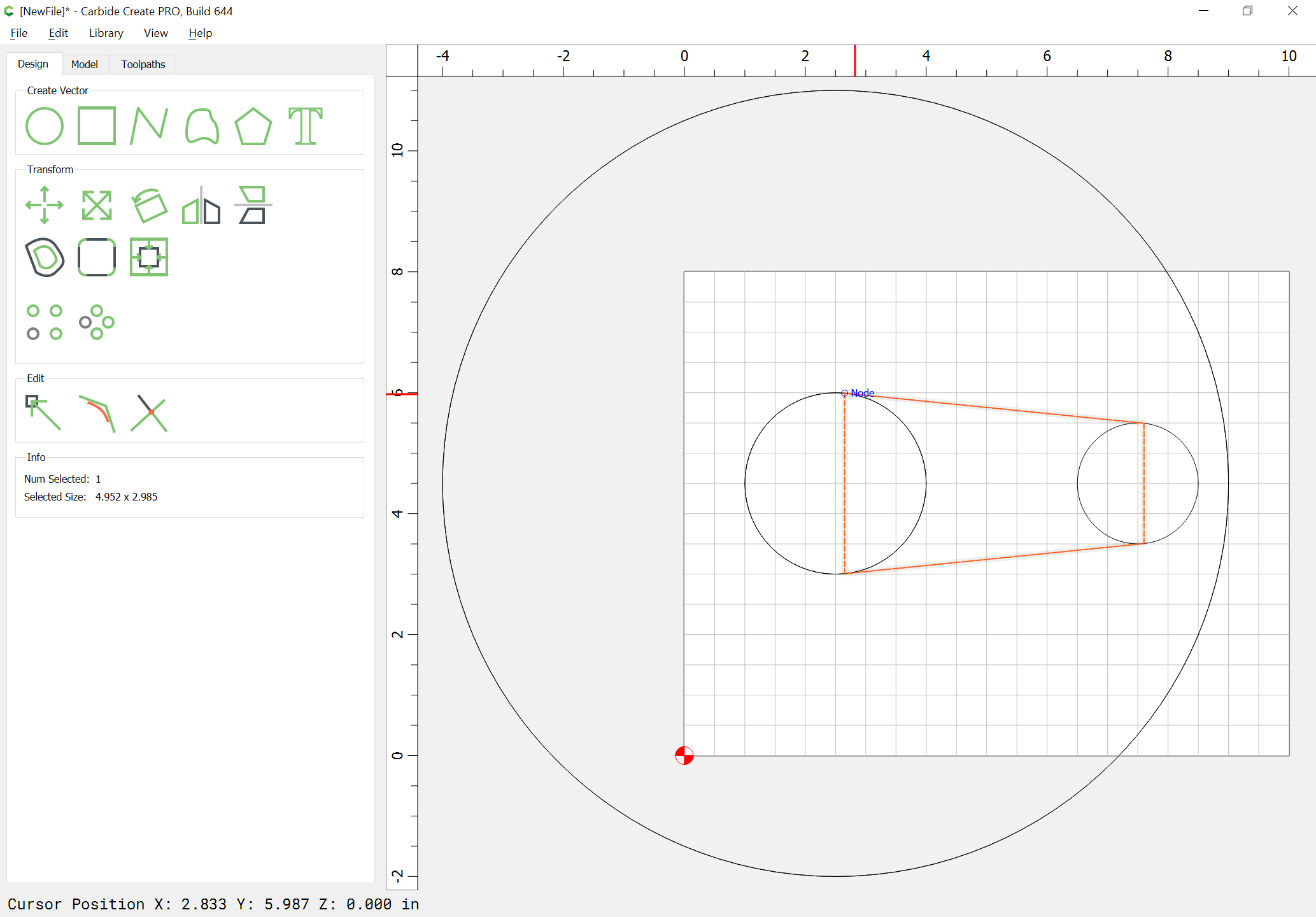
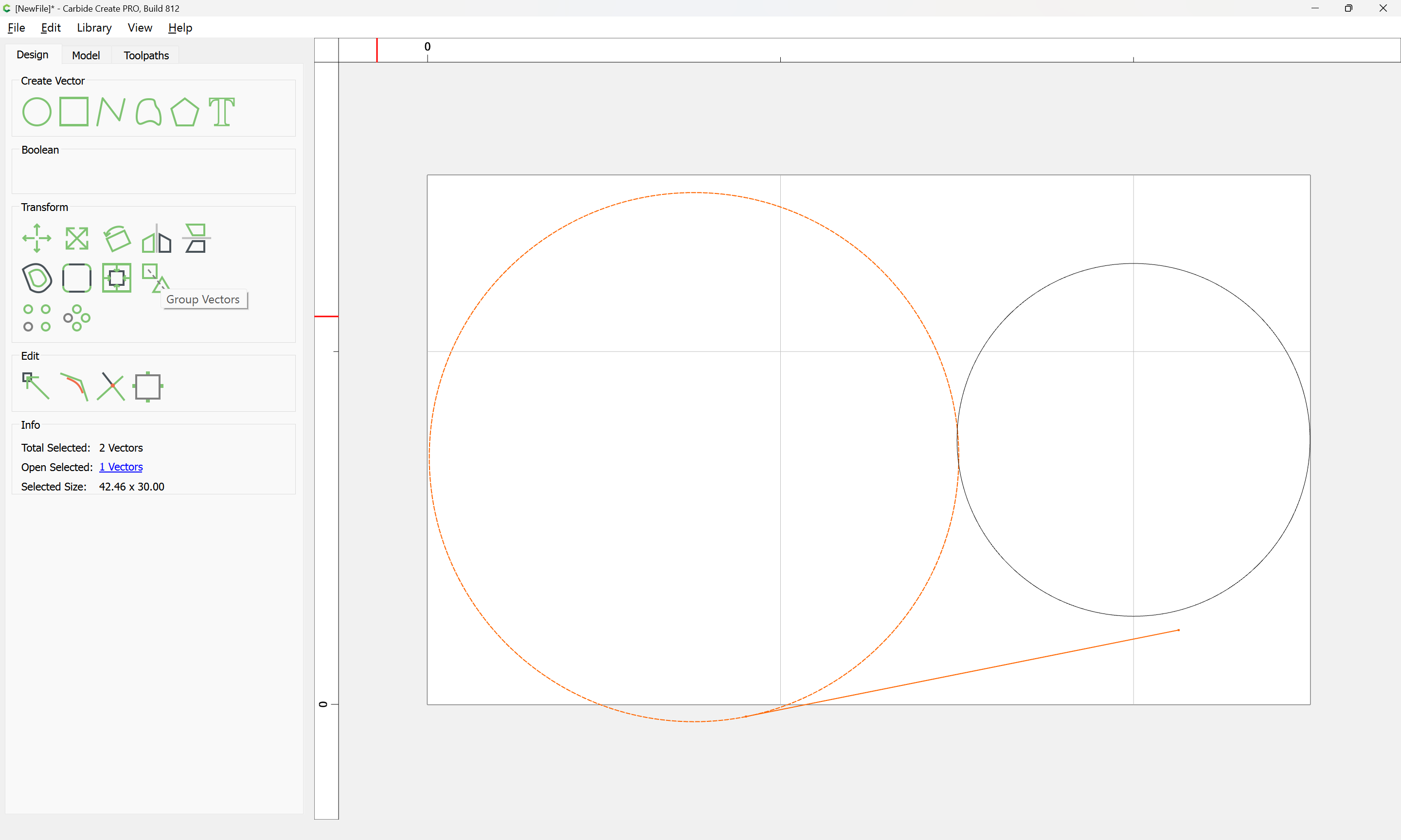
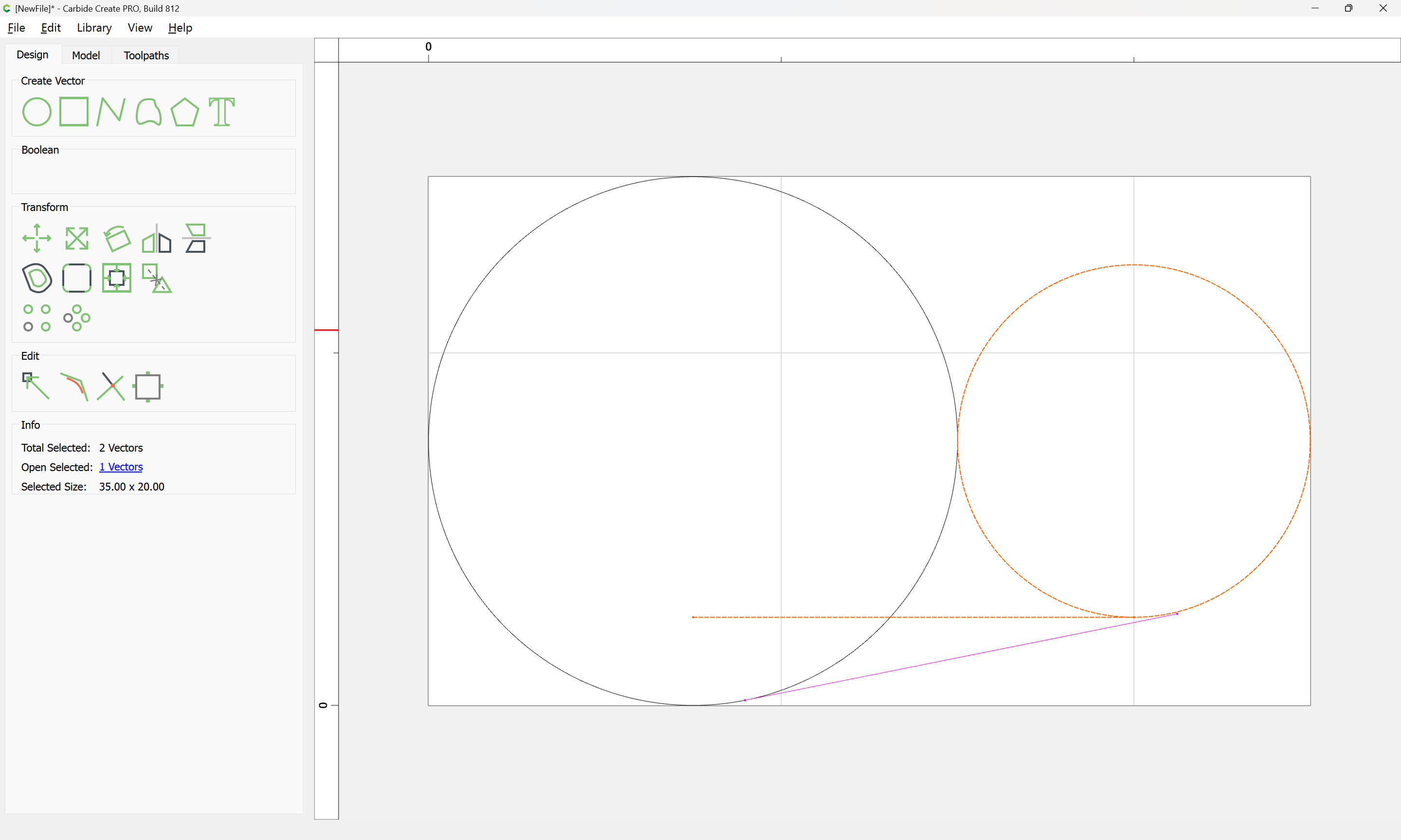
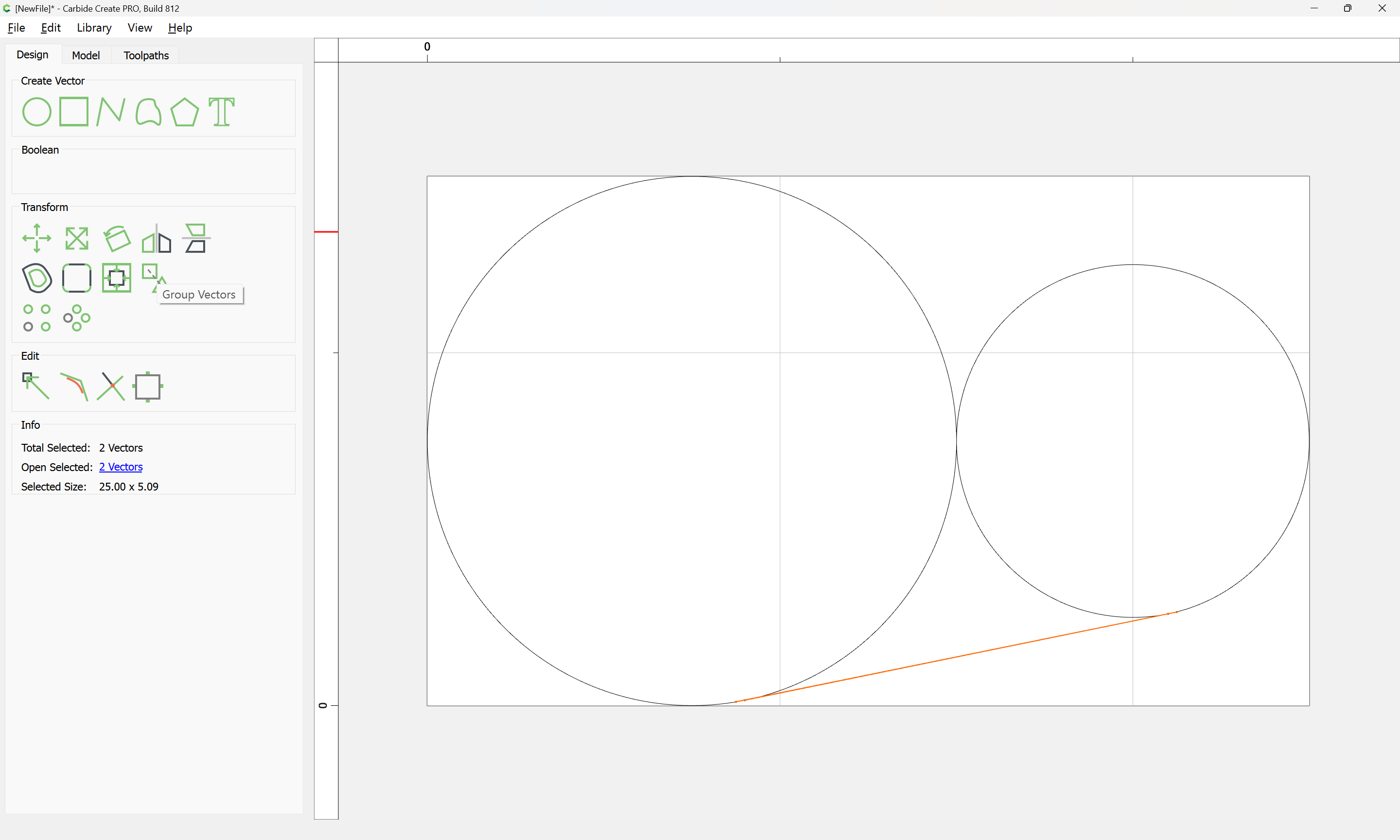
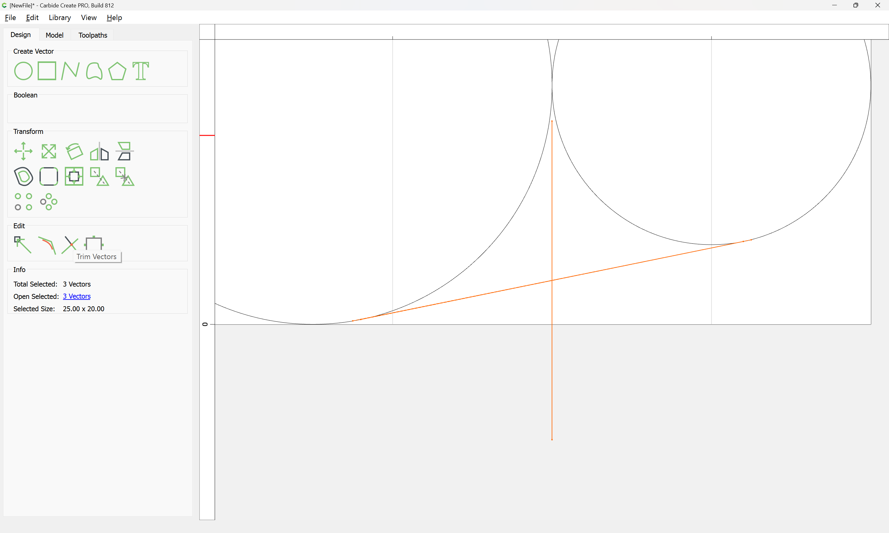
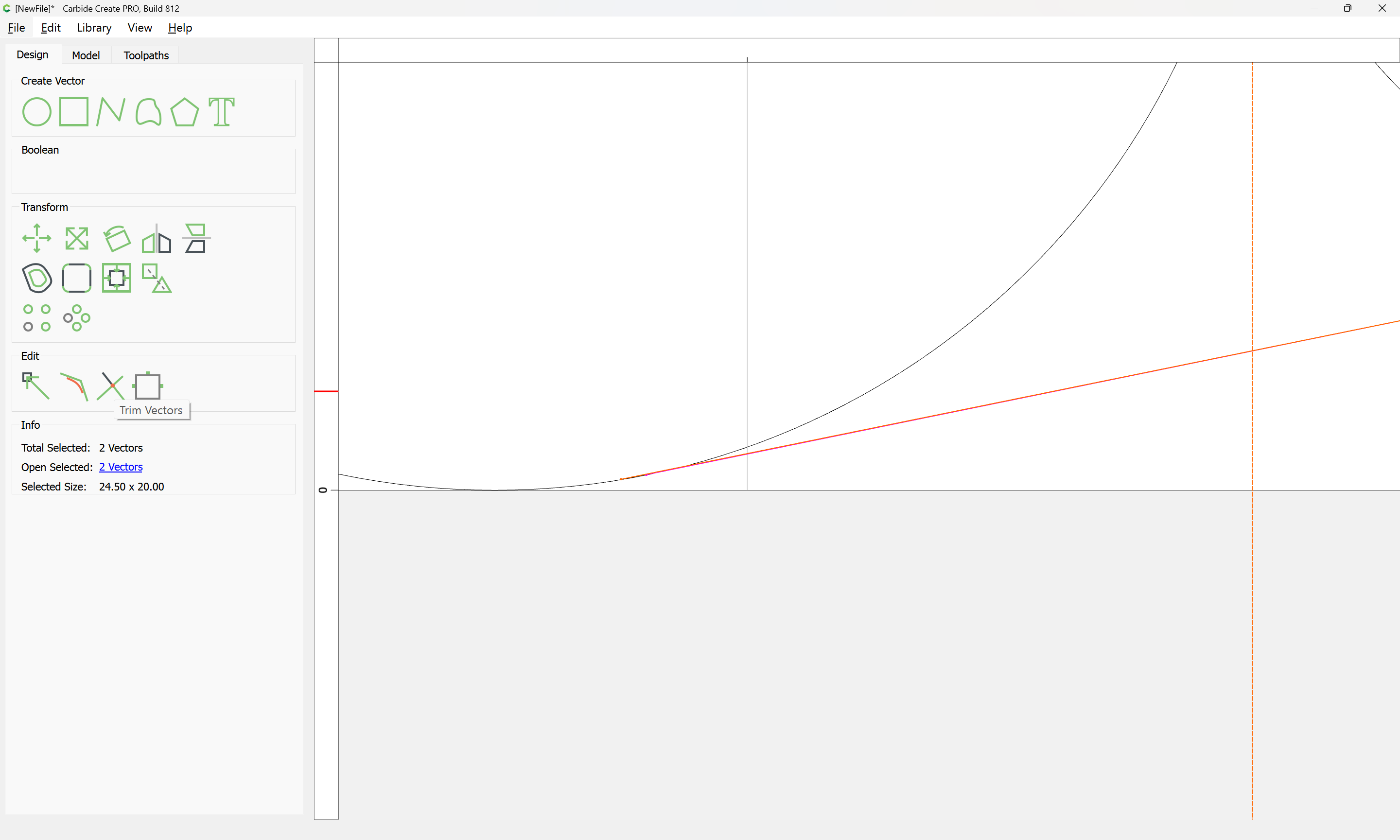
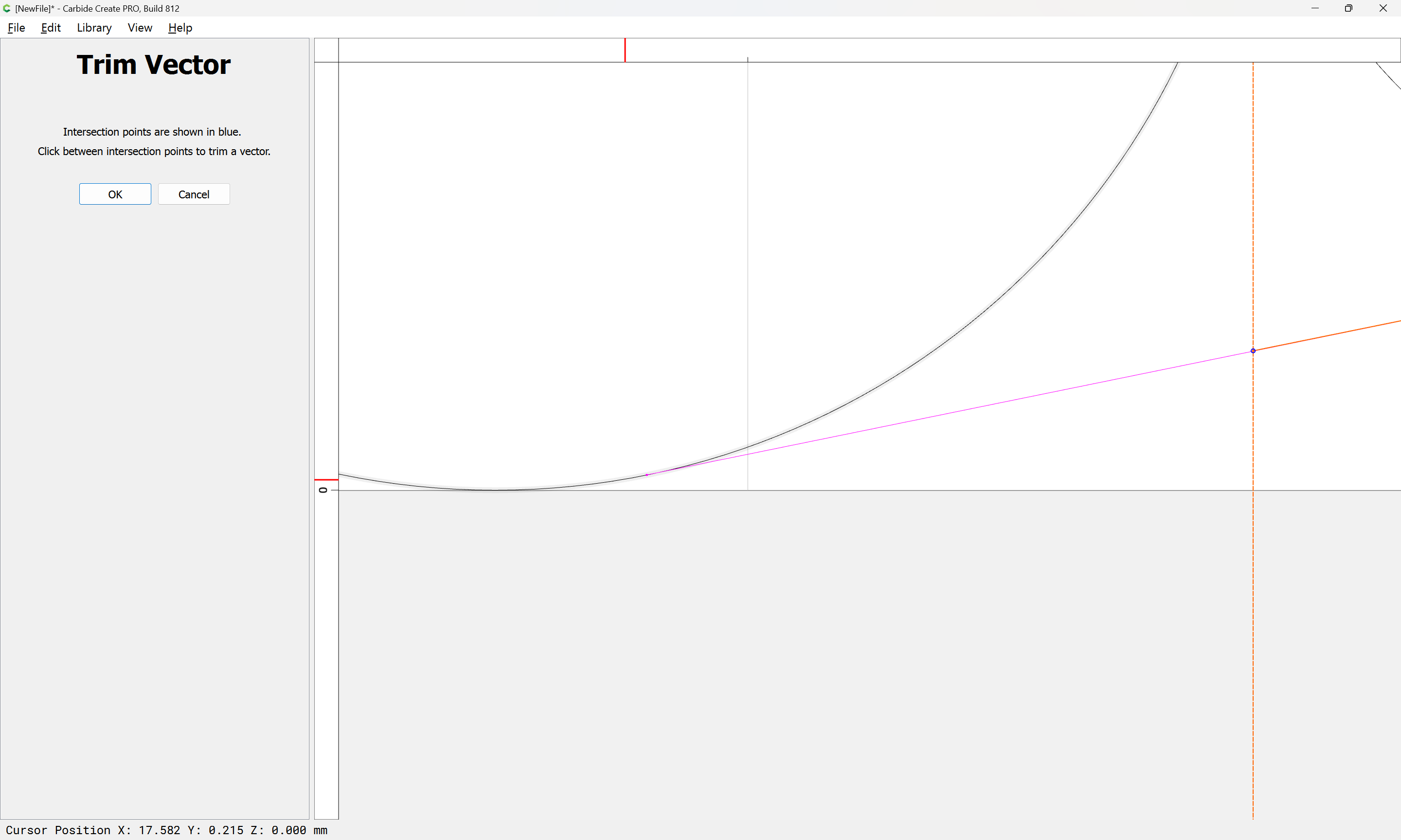
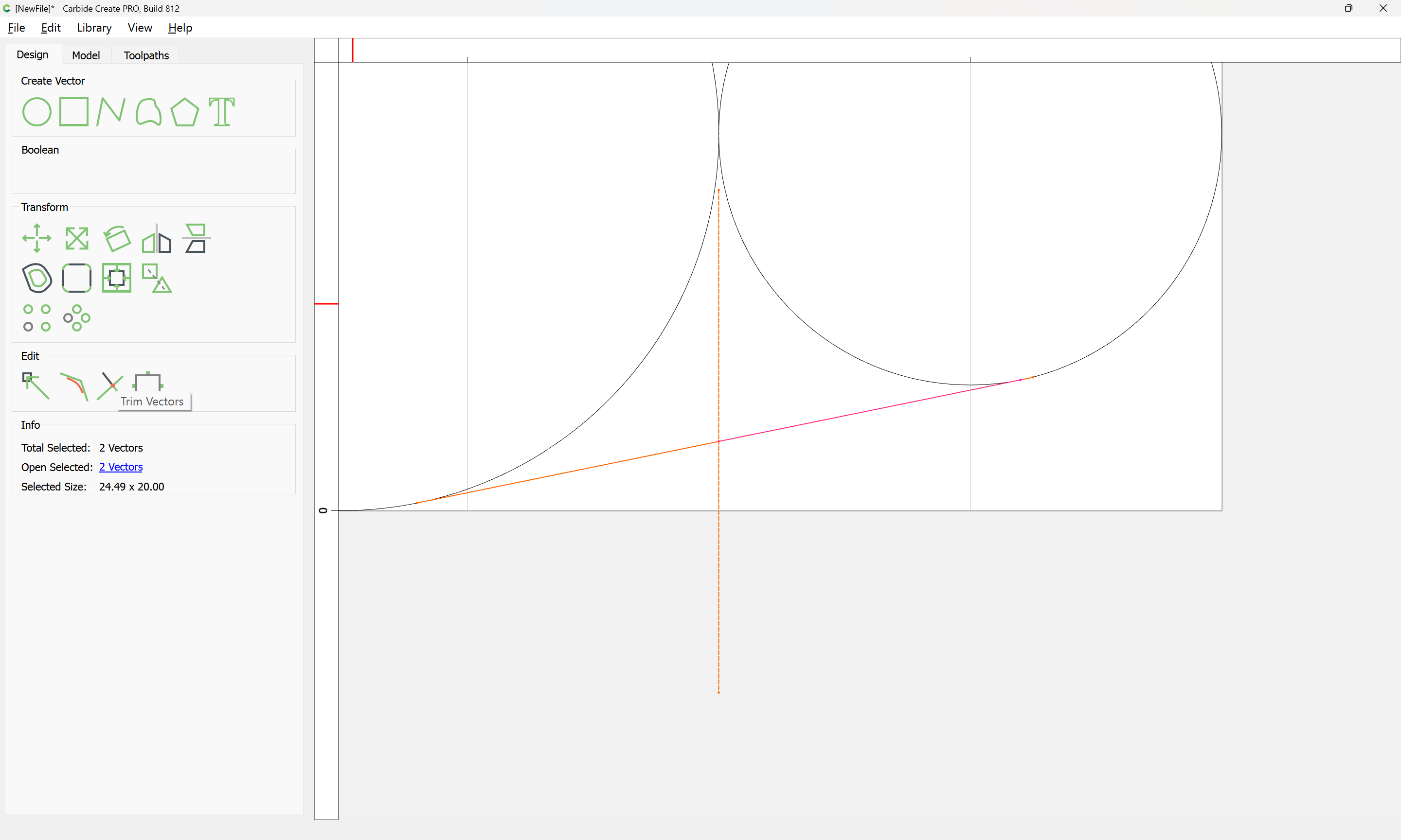
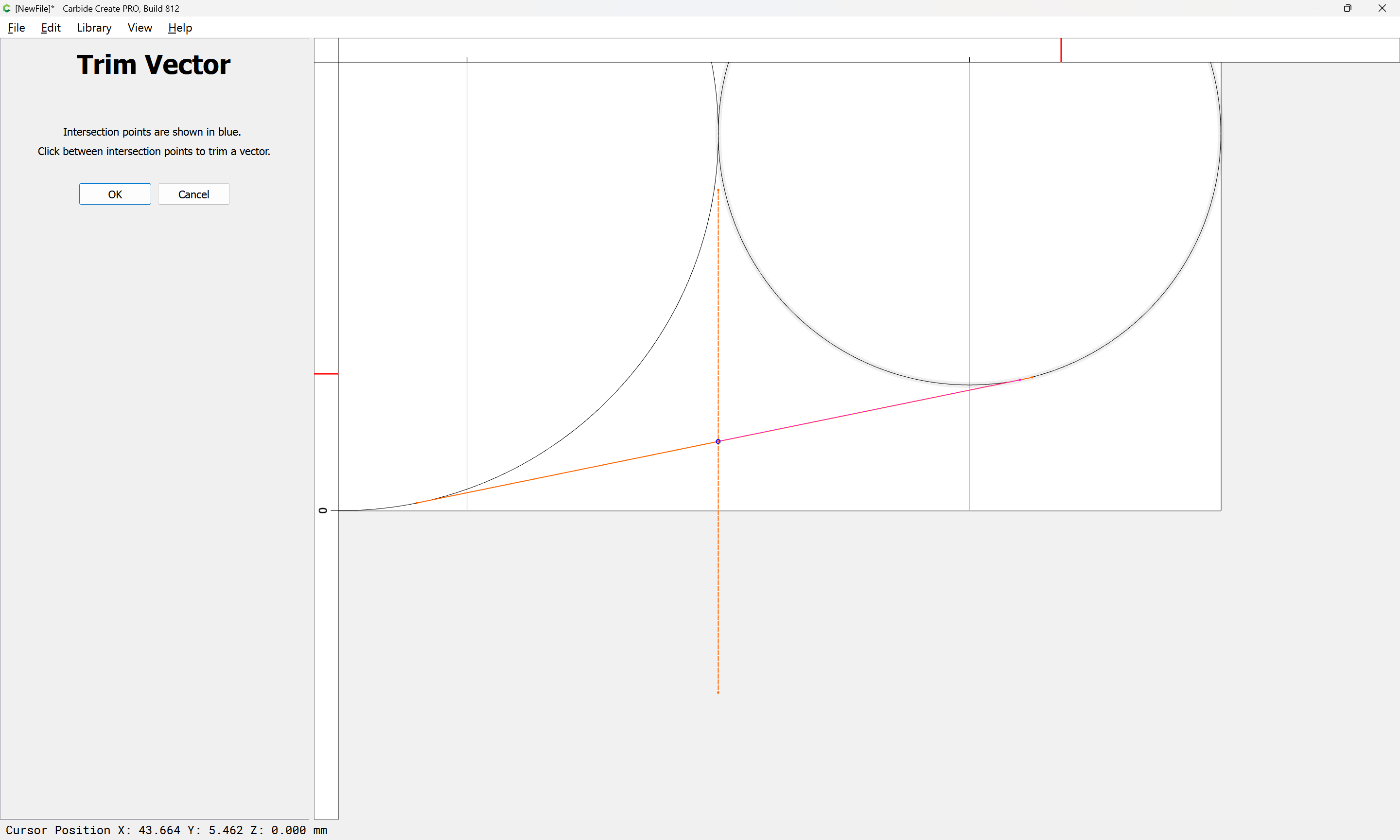
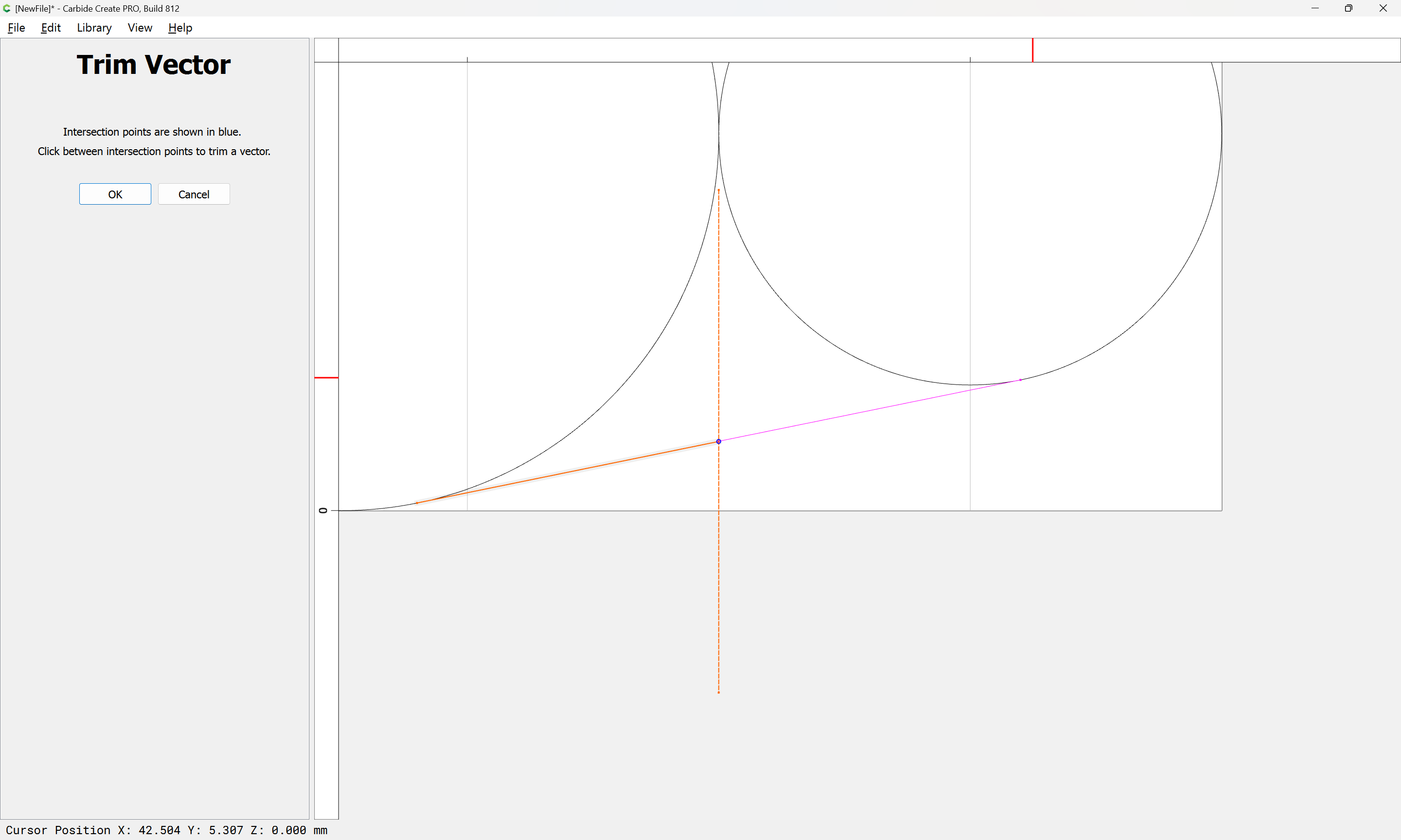
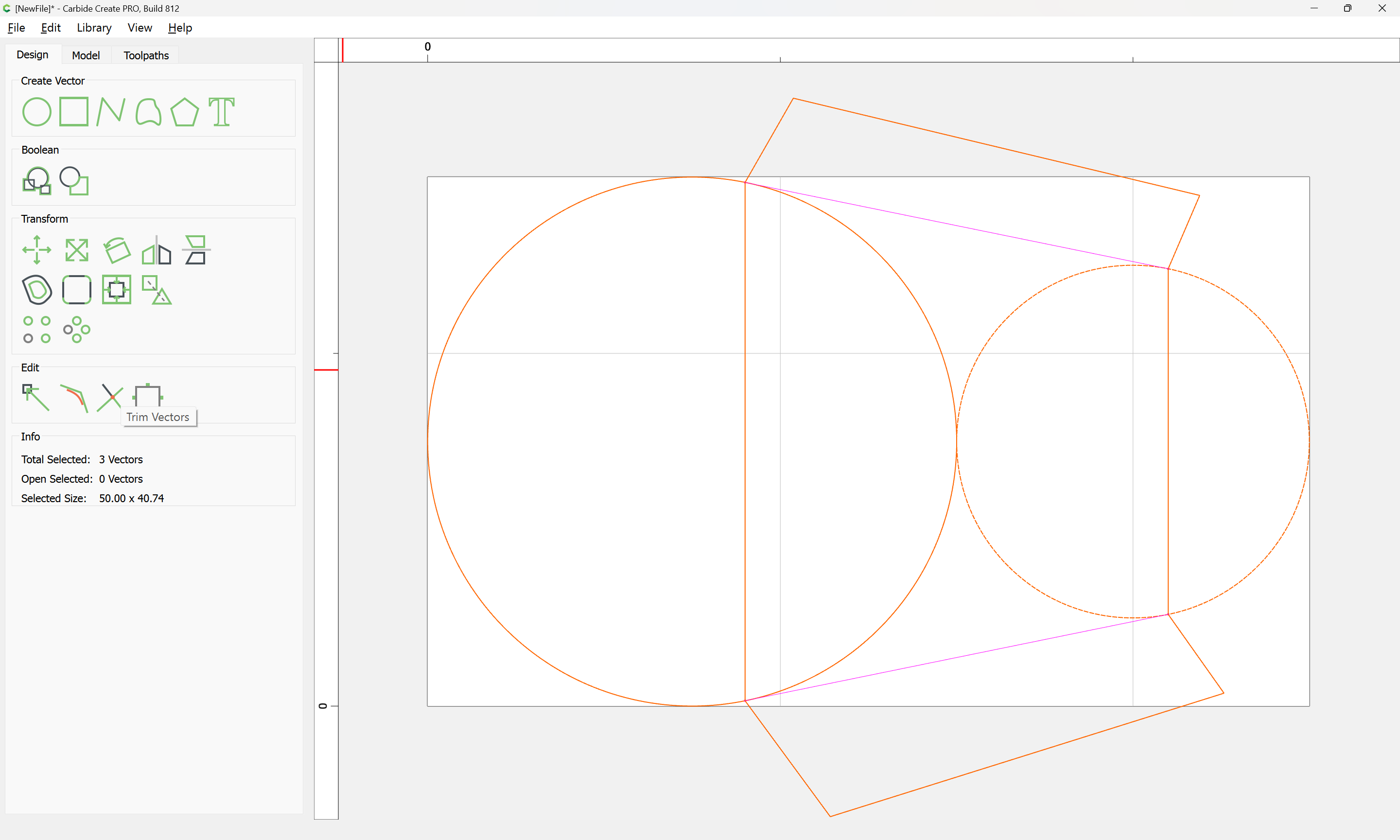
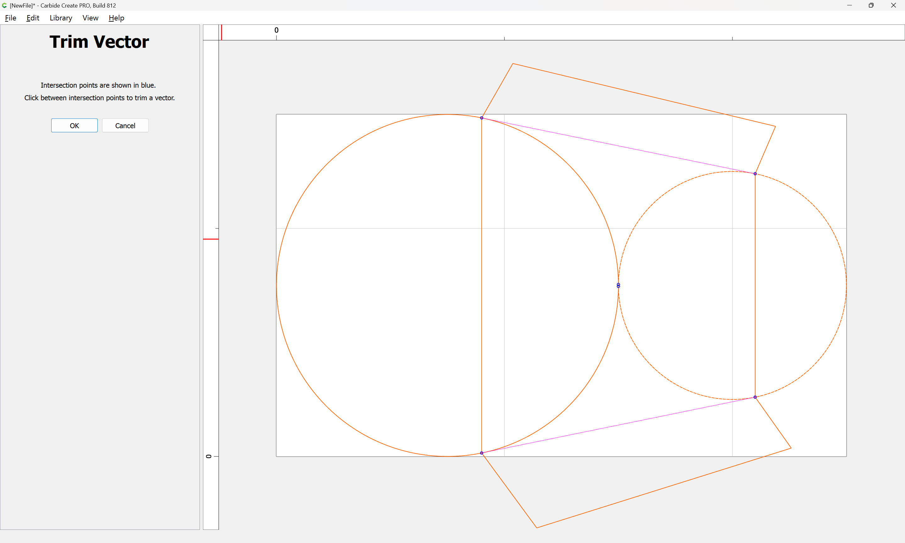
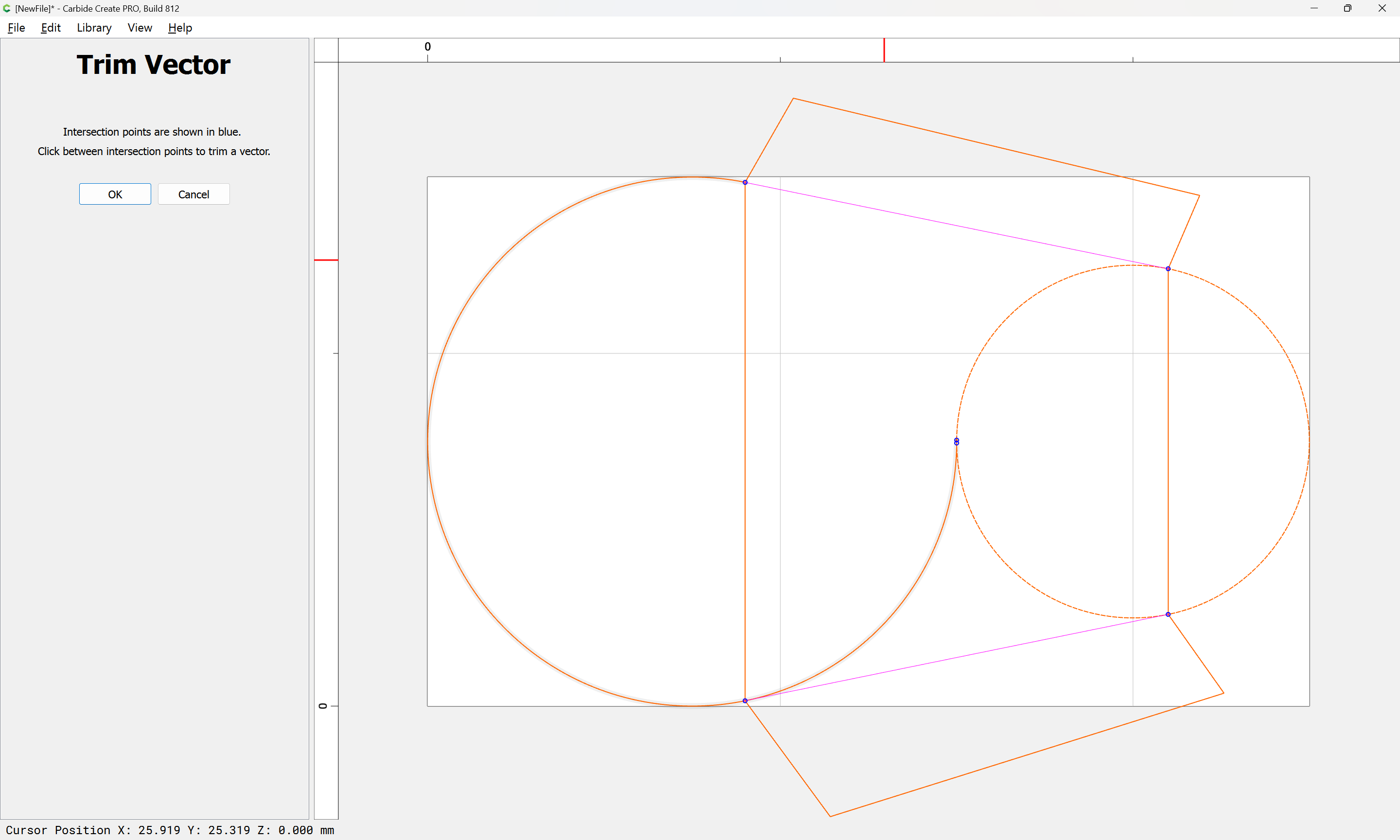
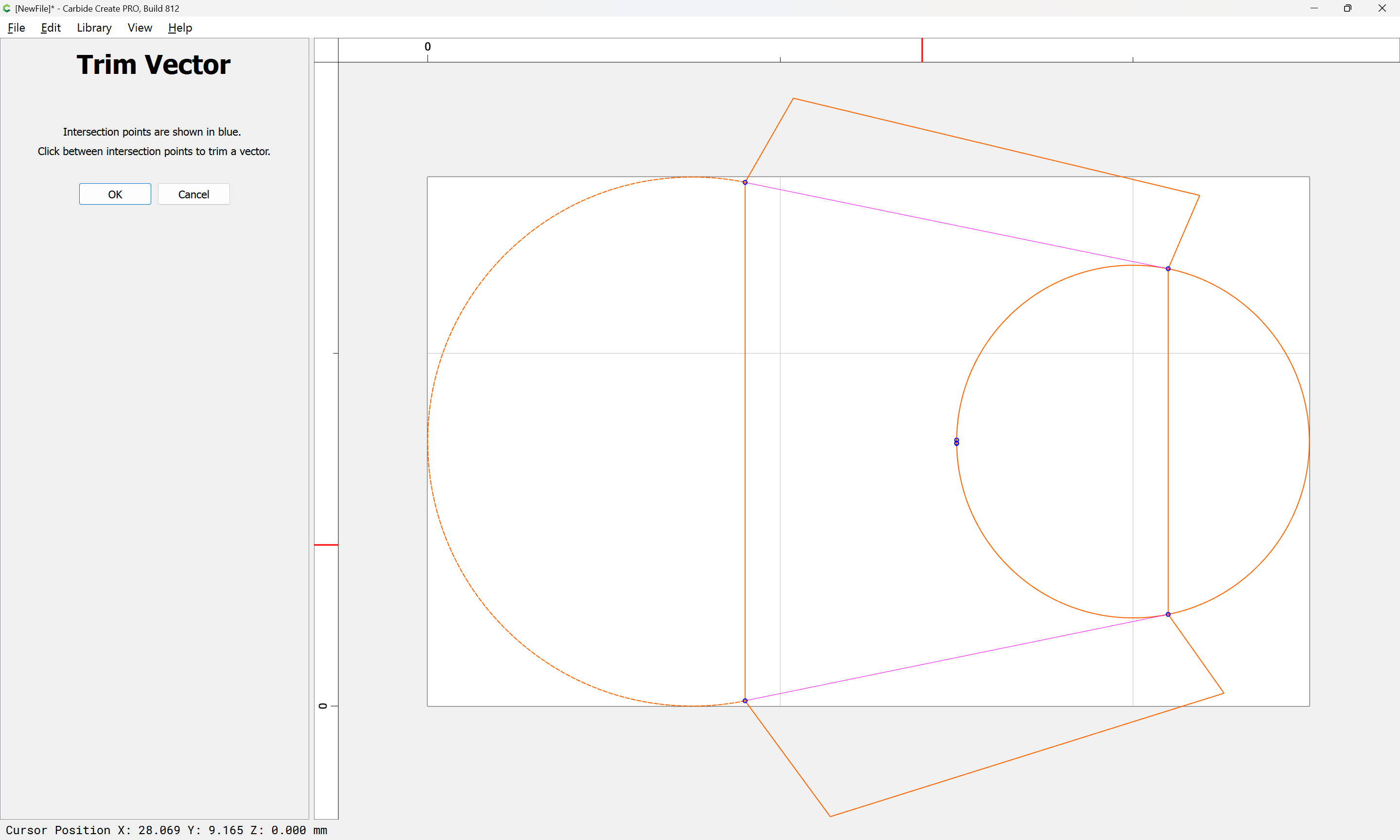
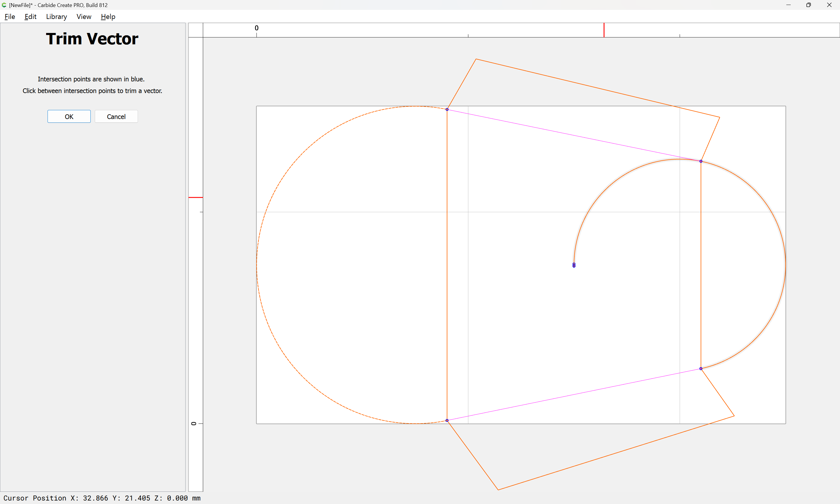
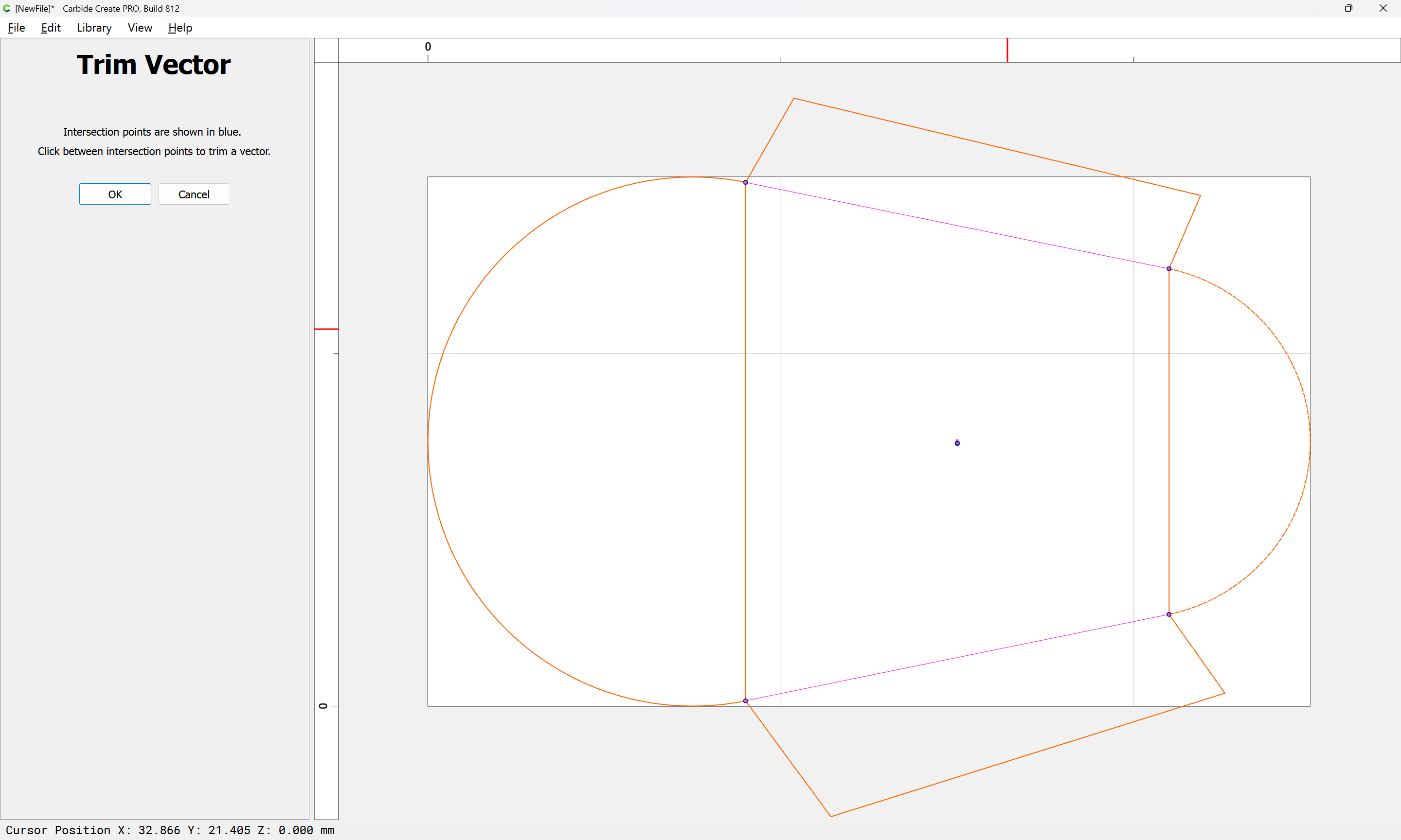
Trim the circles to the intersection of the lines, then you can delete the lines.
If you get the wrong part of the arc, try again & select the other intersection point.

image

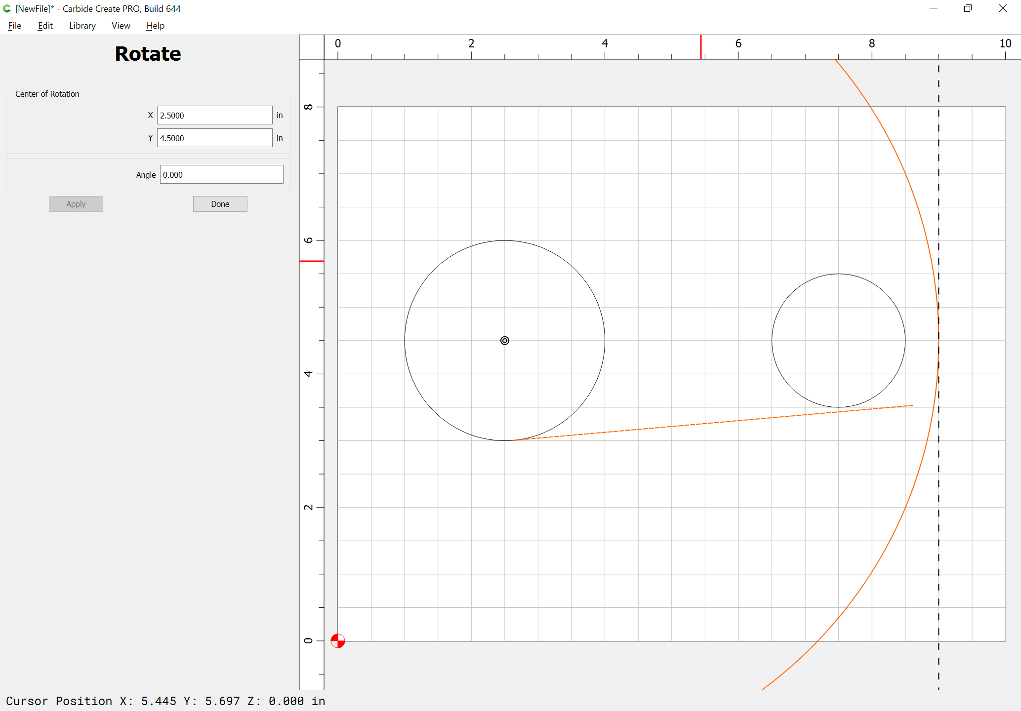
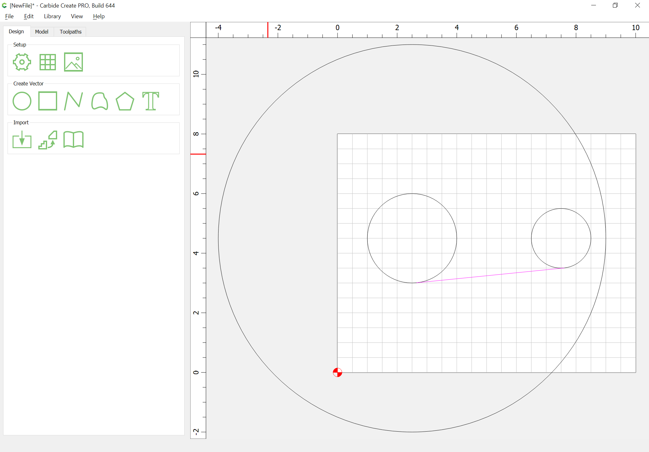
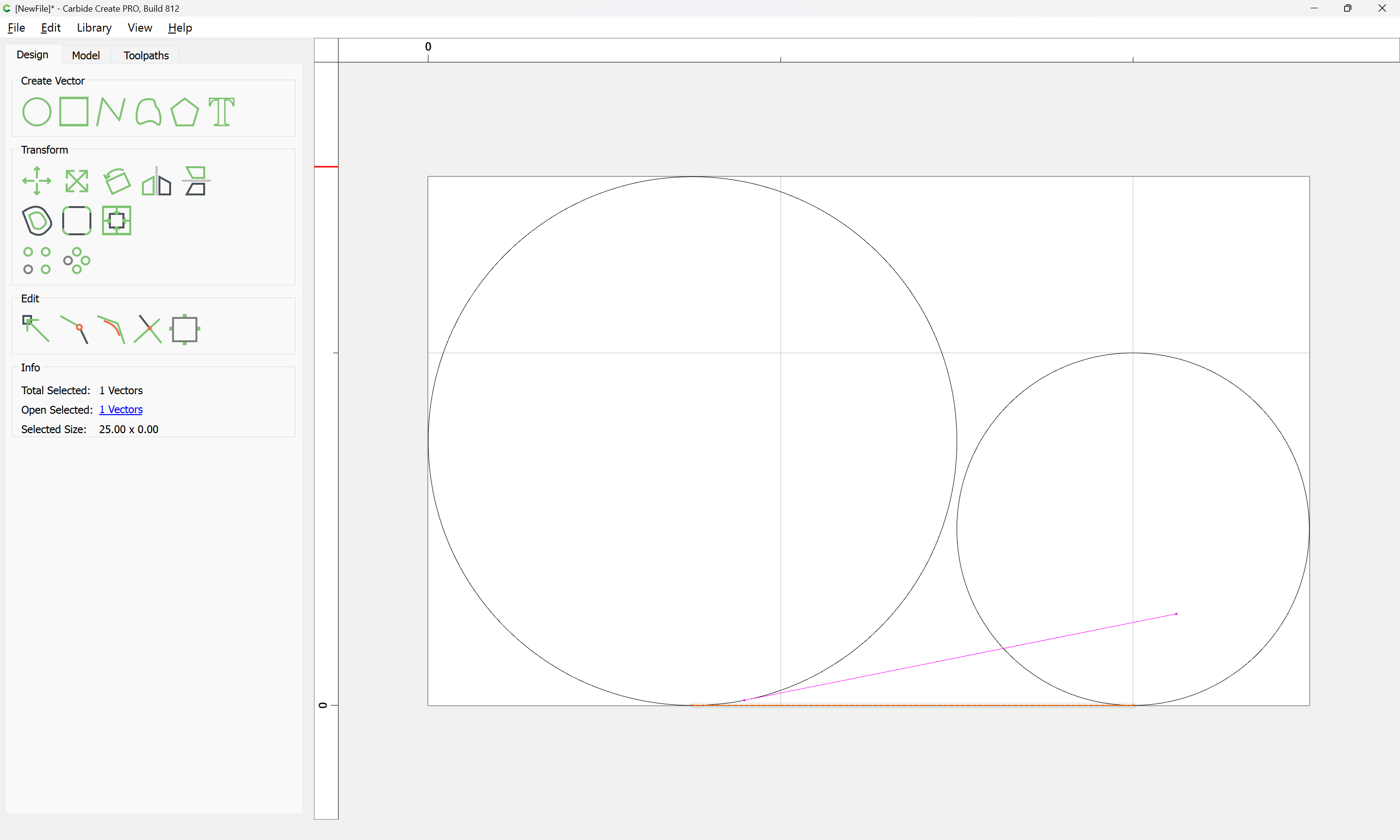
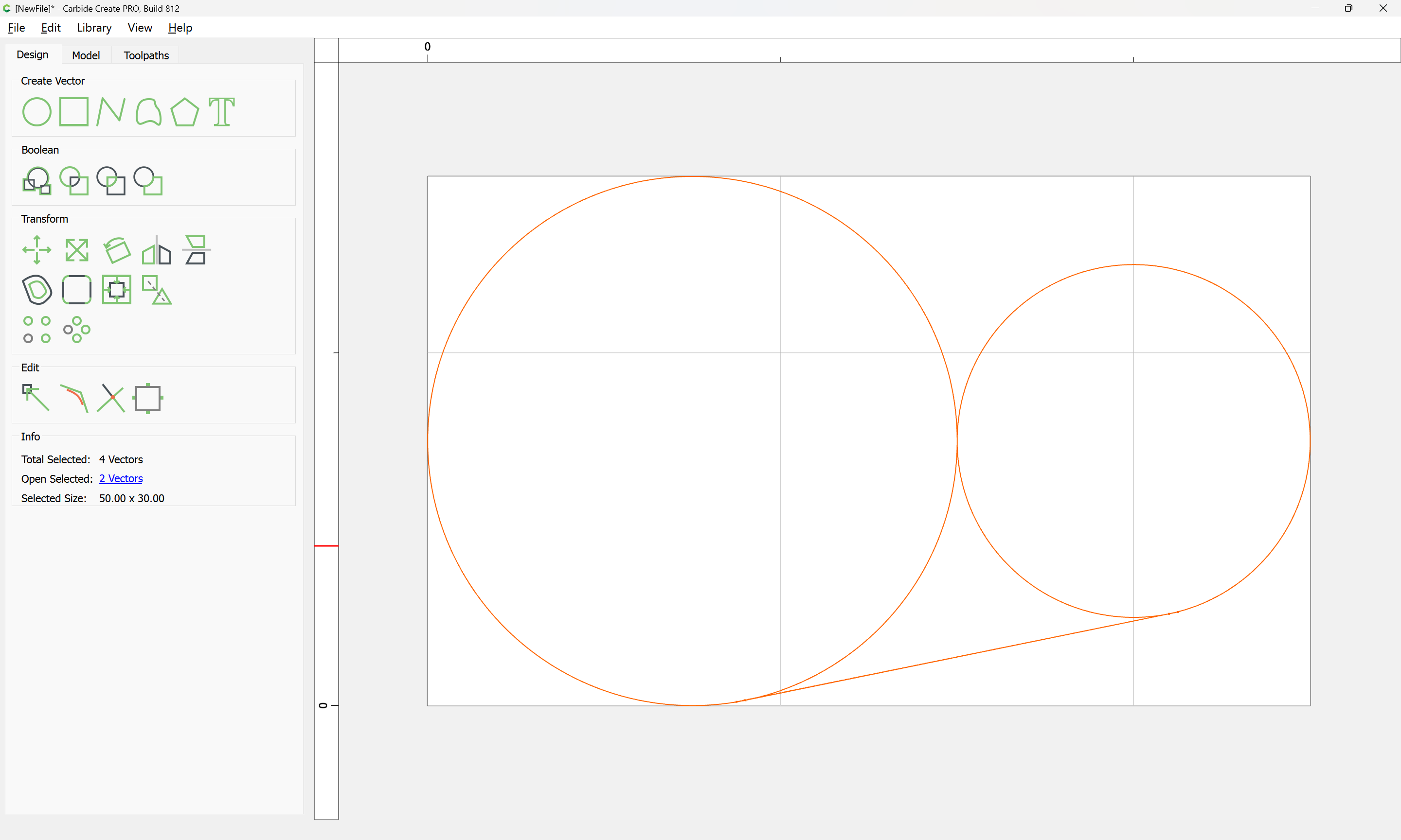
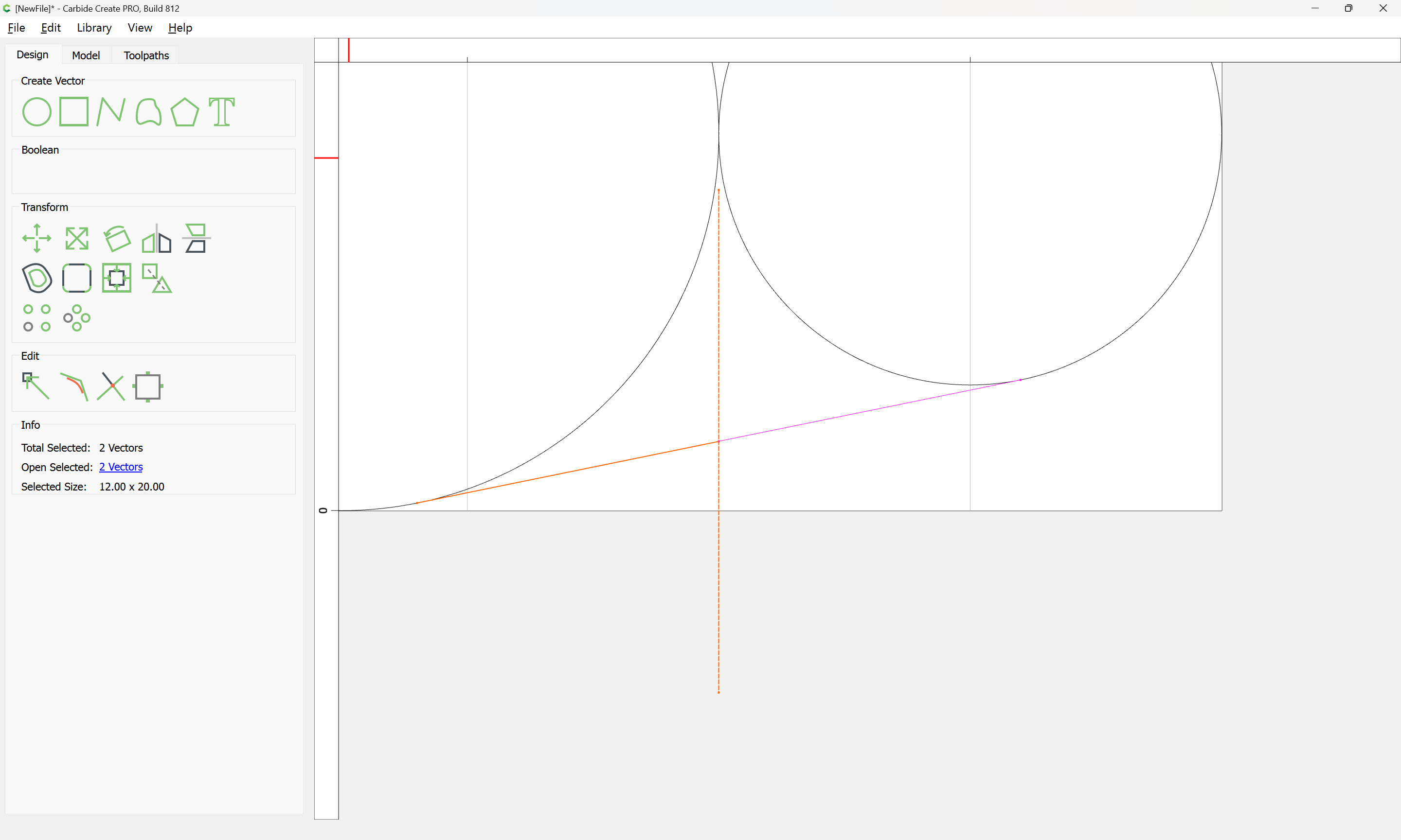
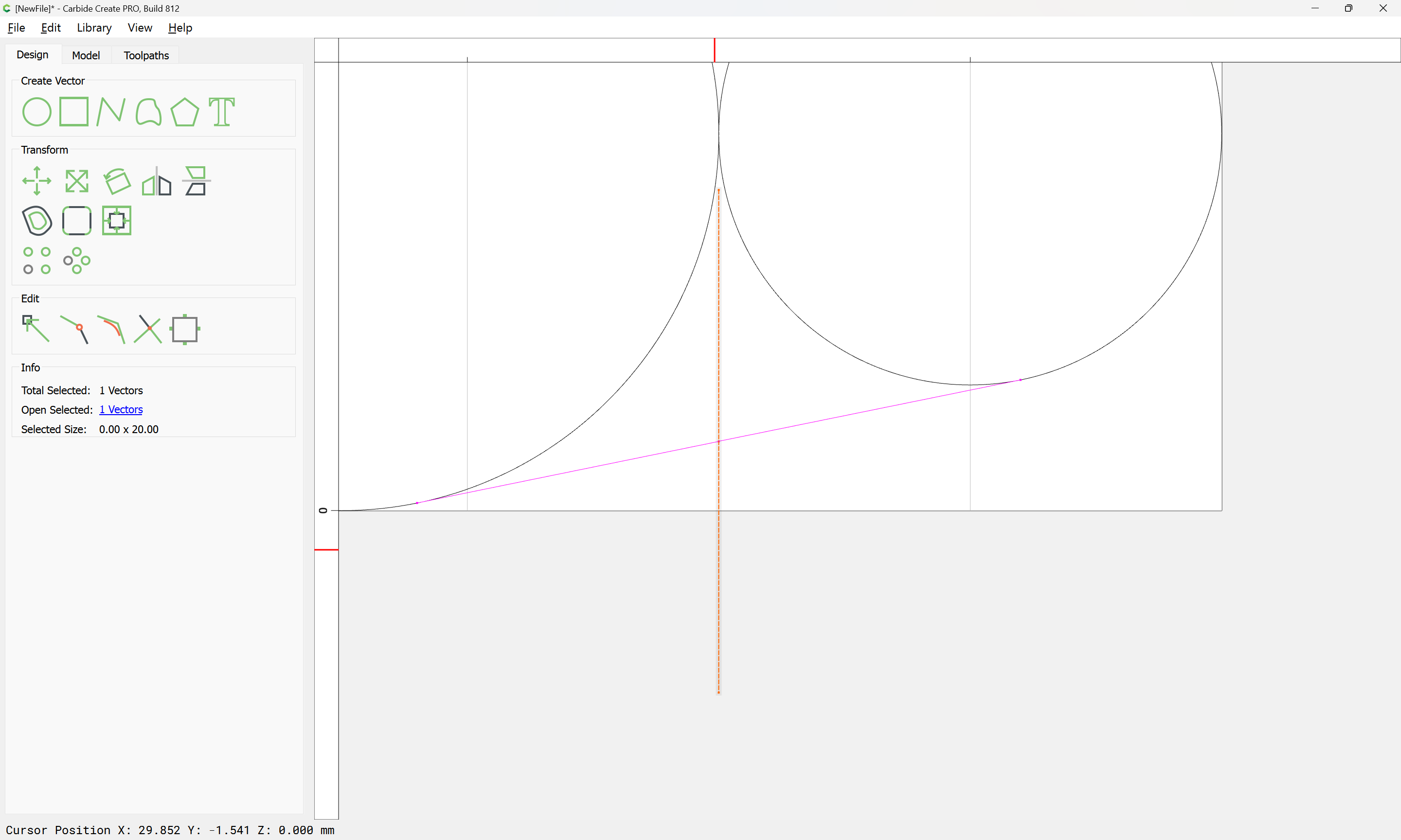
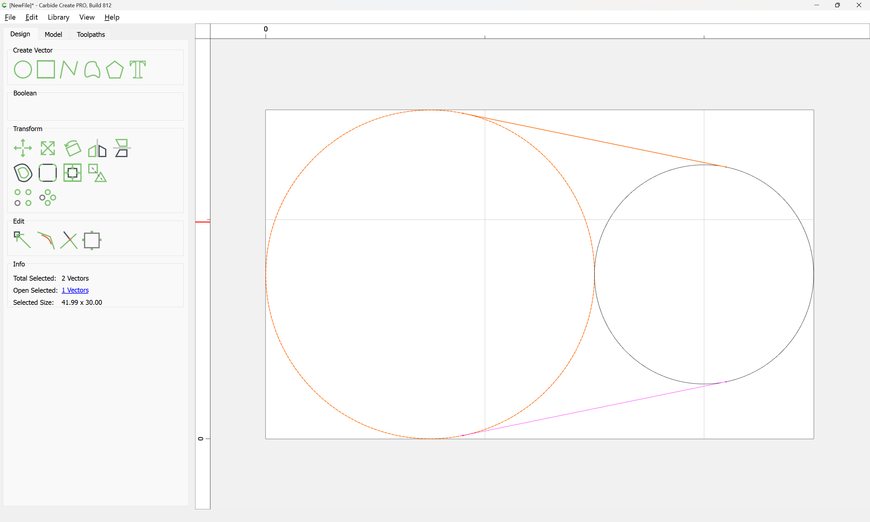
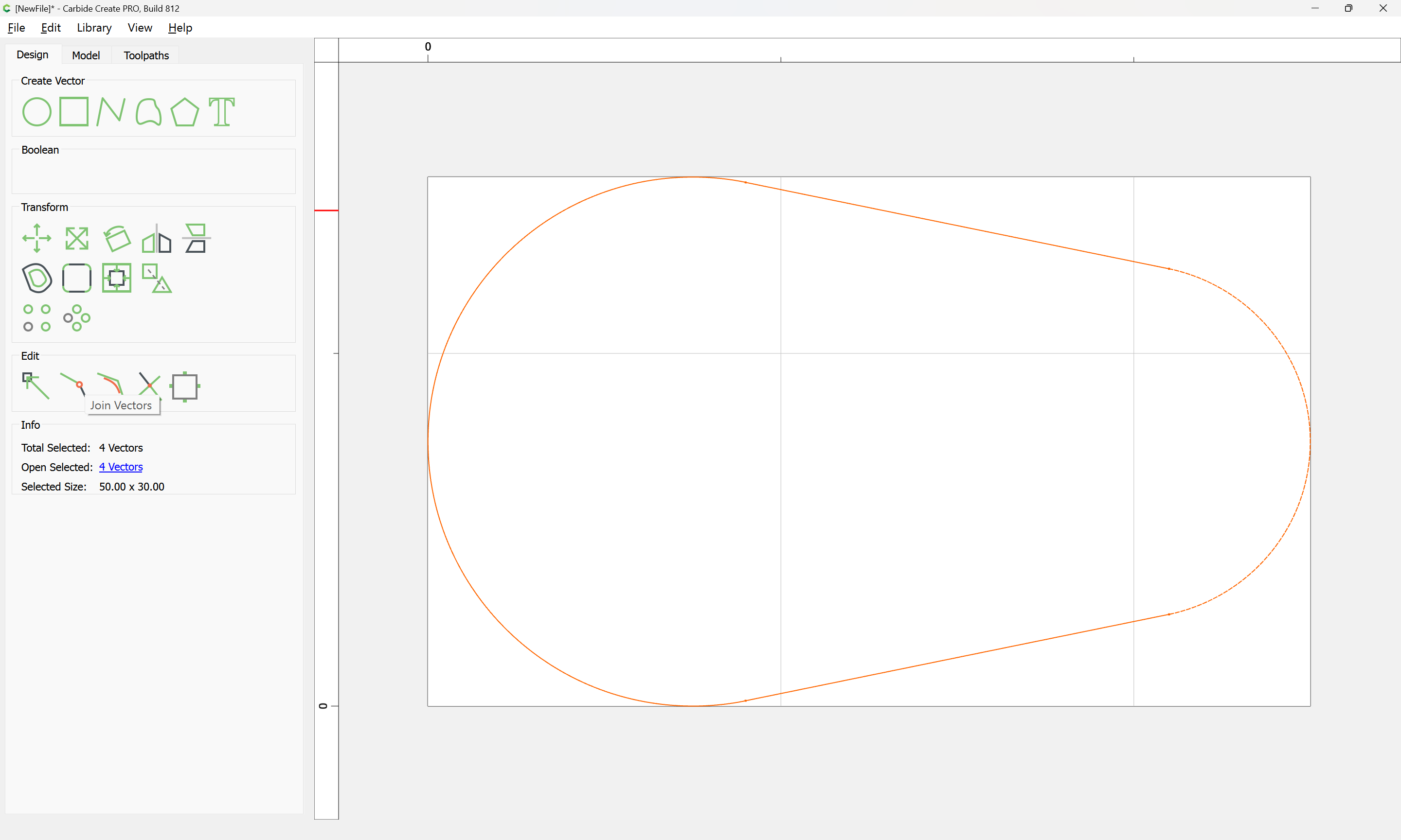
Now connect the ends with a line.

image

Of course this only works if the radii & spacing is an even increment. If they are decimal number that are not easily resolved with grid spacing, you may have to resort to some trigonometry.

5 Likes

I think I can handle Tod’s recommendation. Actual size isn’t all that critical, so I’ll use radii and spacing with some easy to work with numbers and see how it goes.

Thanks to all for your speedy replies.

Jim

Another option is to do the following.

Draw your circle size.


Connect with poly lines.

Use new trim function. Then use the Join Vector function.

Create toolpath.

No Math Needed.

1 Like

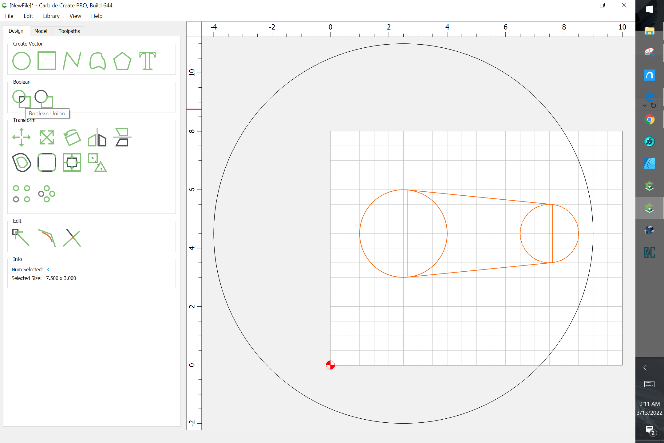
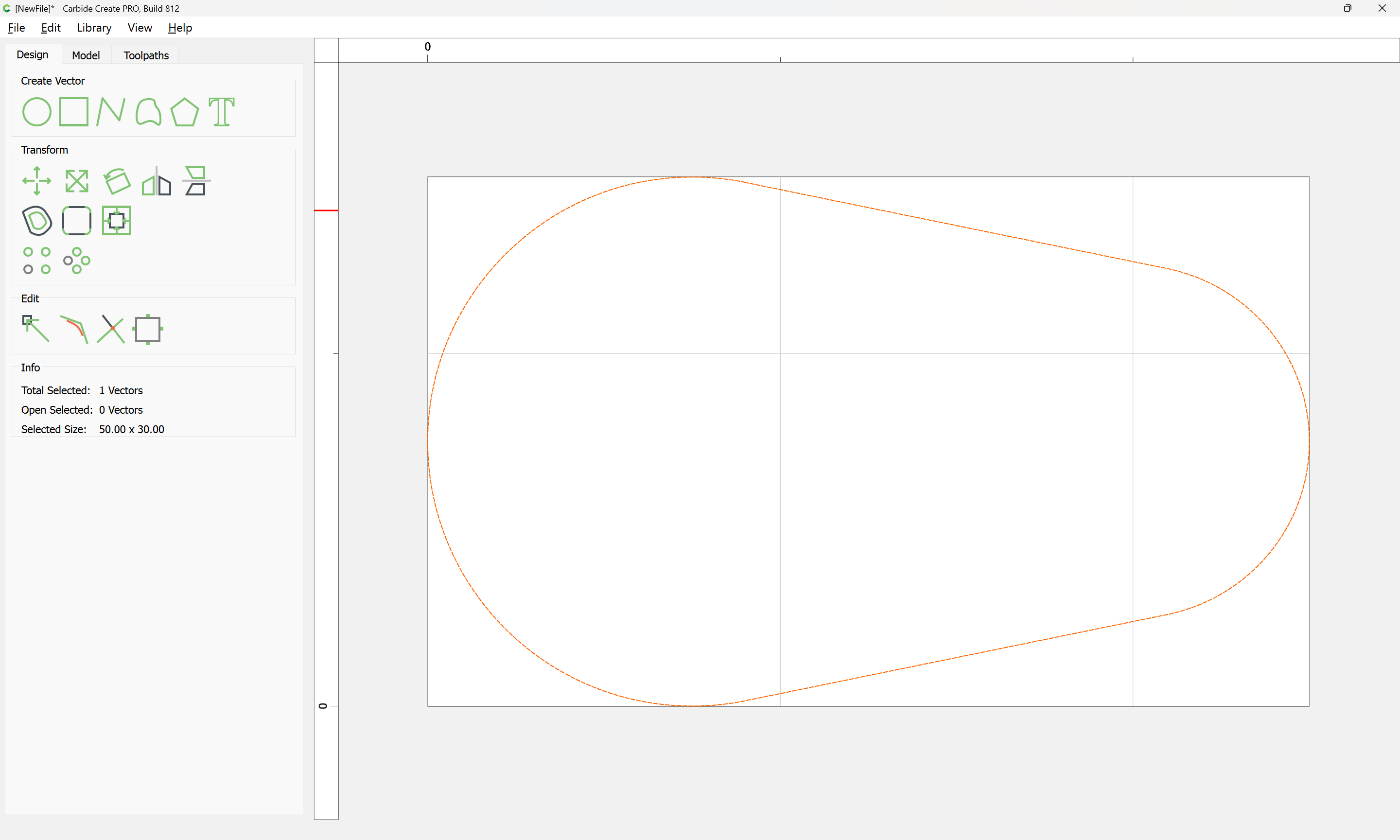
Thank you all for the replies. I ended up doing what Eric suggested, but rather than using the new trim tool I continued the poly line through the circles and used one of the Booleans to clear the center out. It worked out just fine.

Thank you all once again,

Jim

If you’re looking for an approximate tangent, then for sure Eric’s method is the quickest.
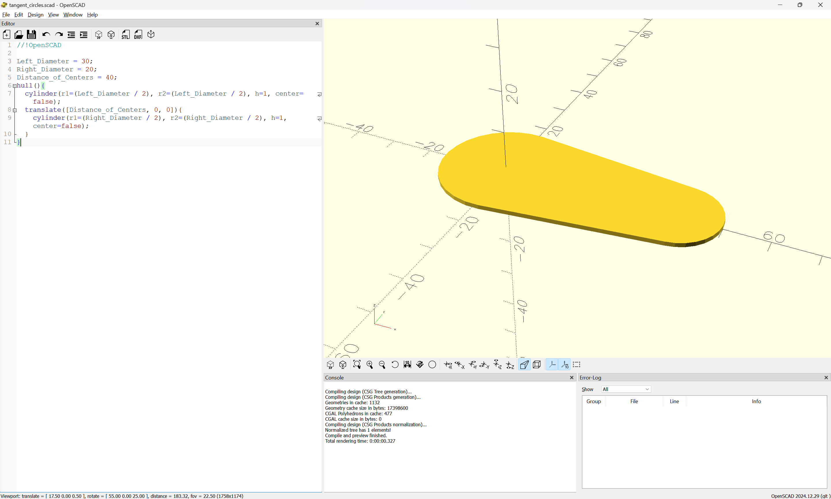
If you wanted an exact tangent, then my or Will’s solution would be more accurate.

1 Like

Not sure what you mean by exact tangent?

If the circles are the right size, and the correct distance apart, would this not create the part needed and serve the same outcome?

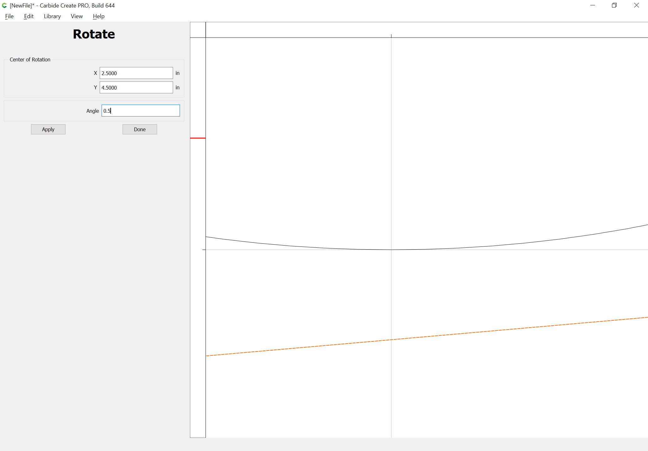
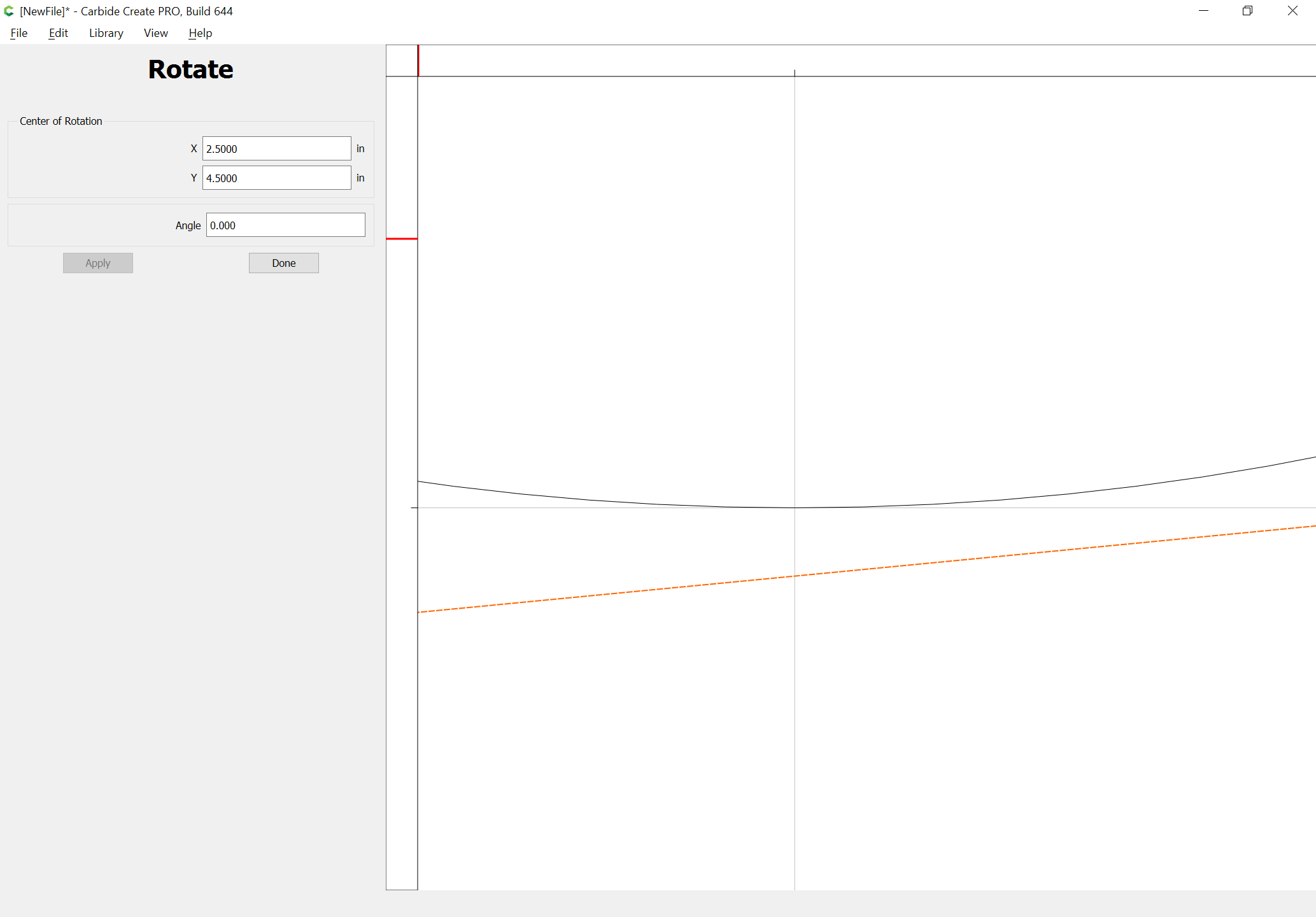
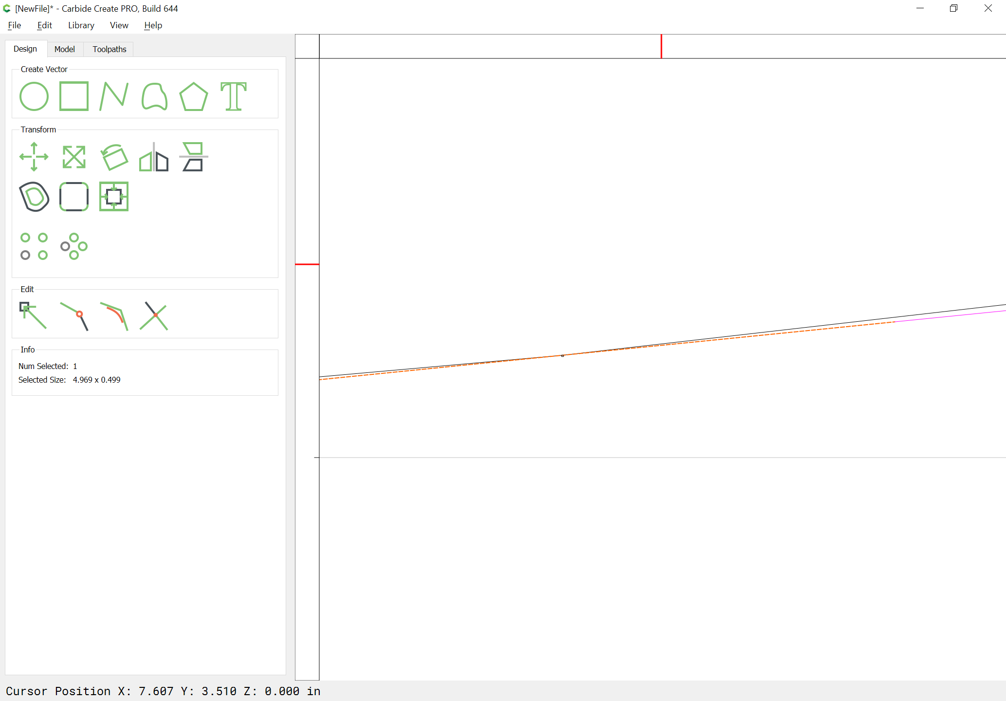
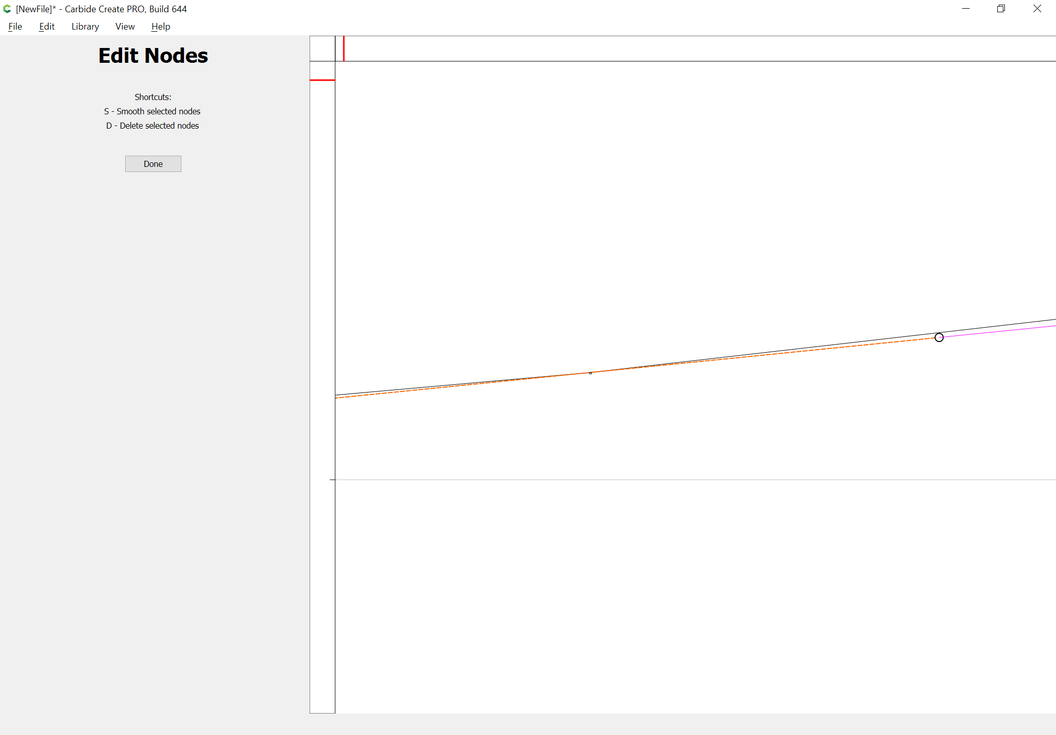
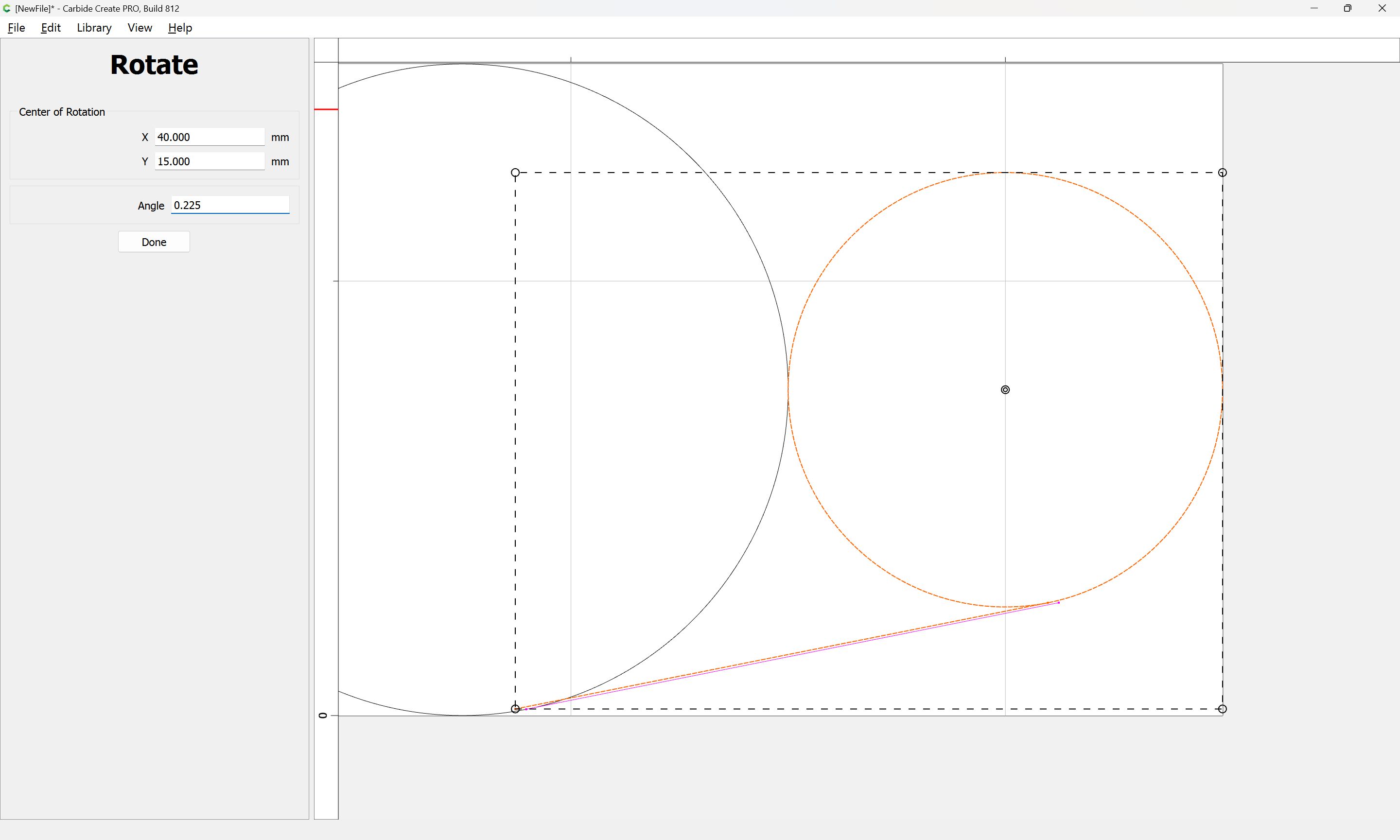
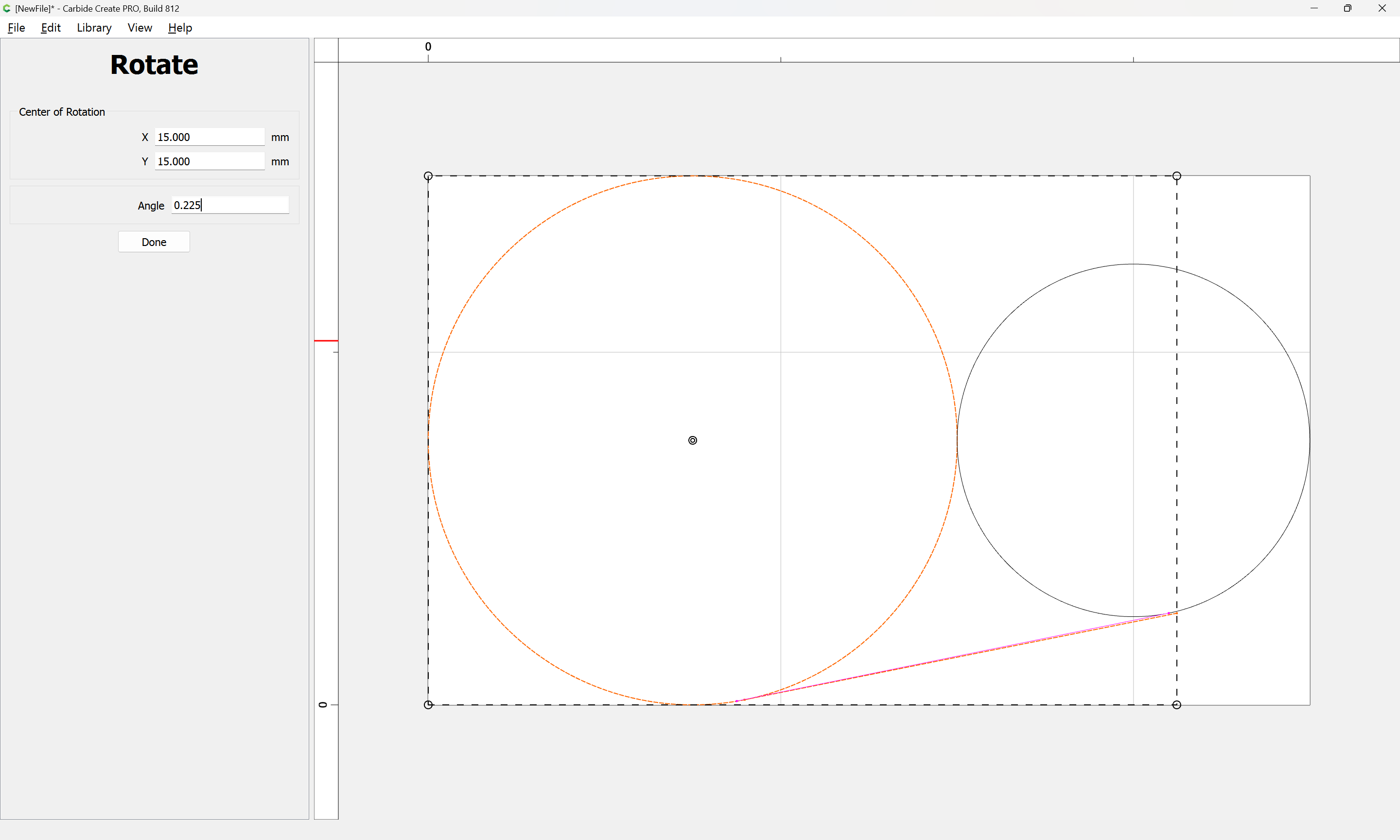
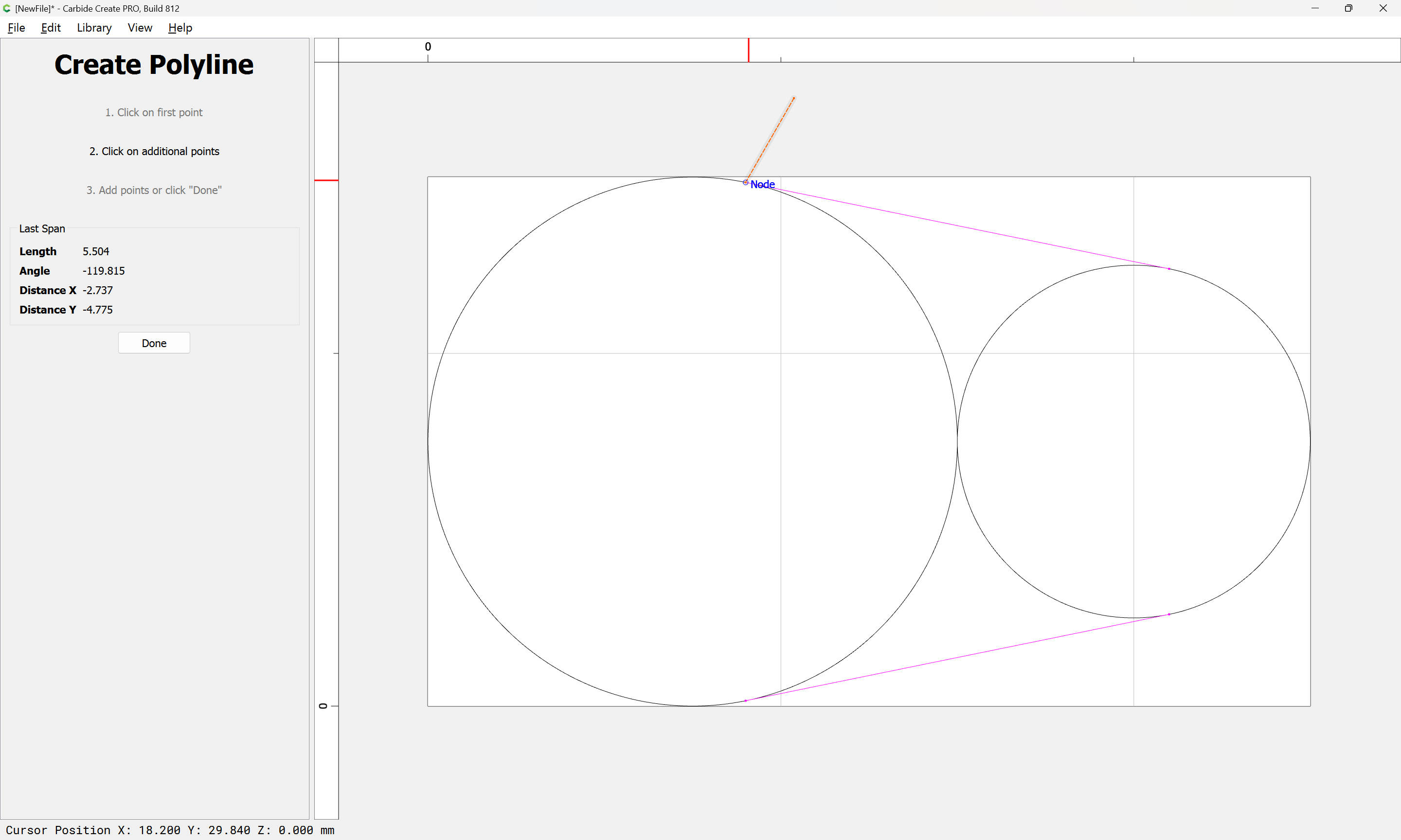
You have to zoom in, a lot to get things lined up perfectly, and once you do one end, you need to go back to the other and adjust it again, and repeat.

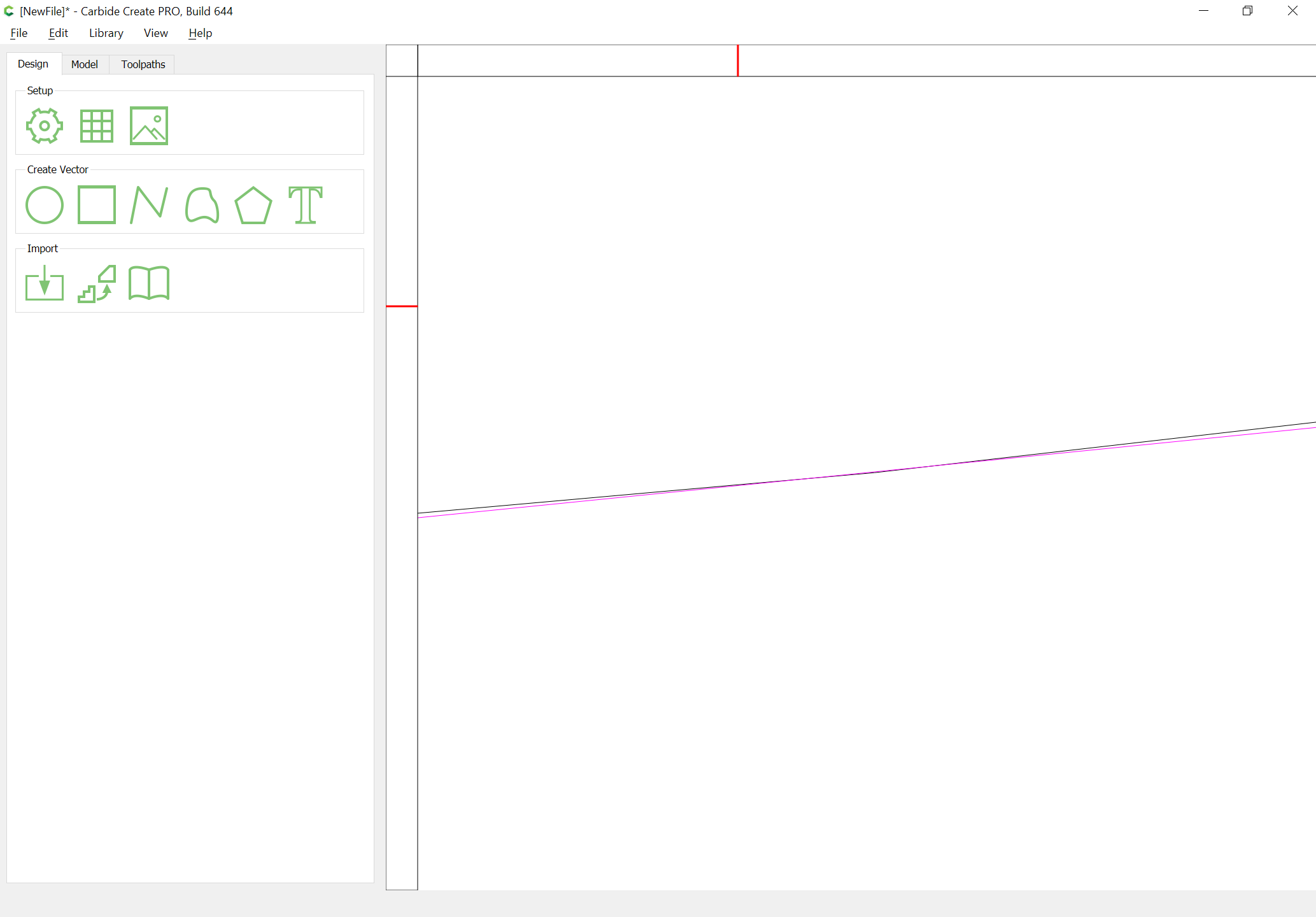
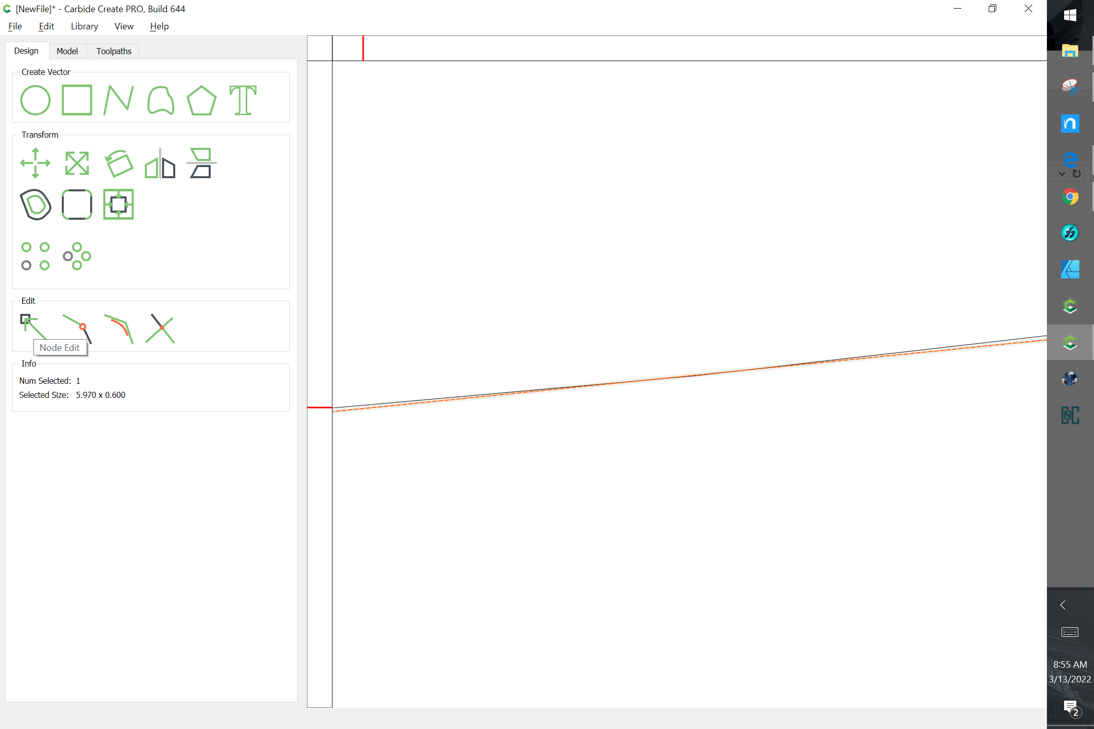
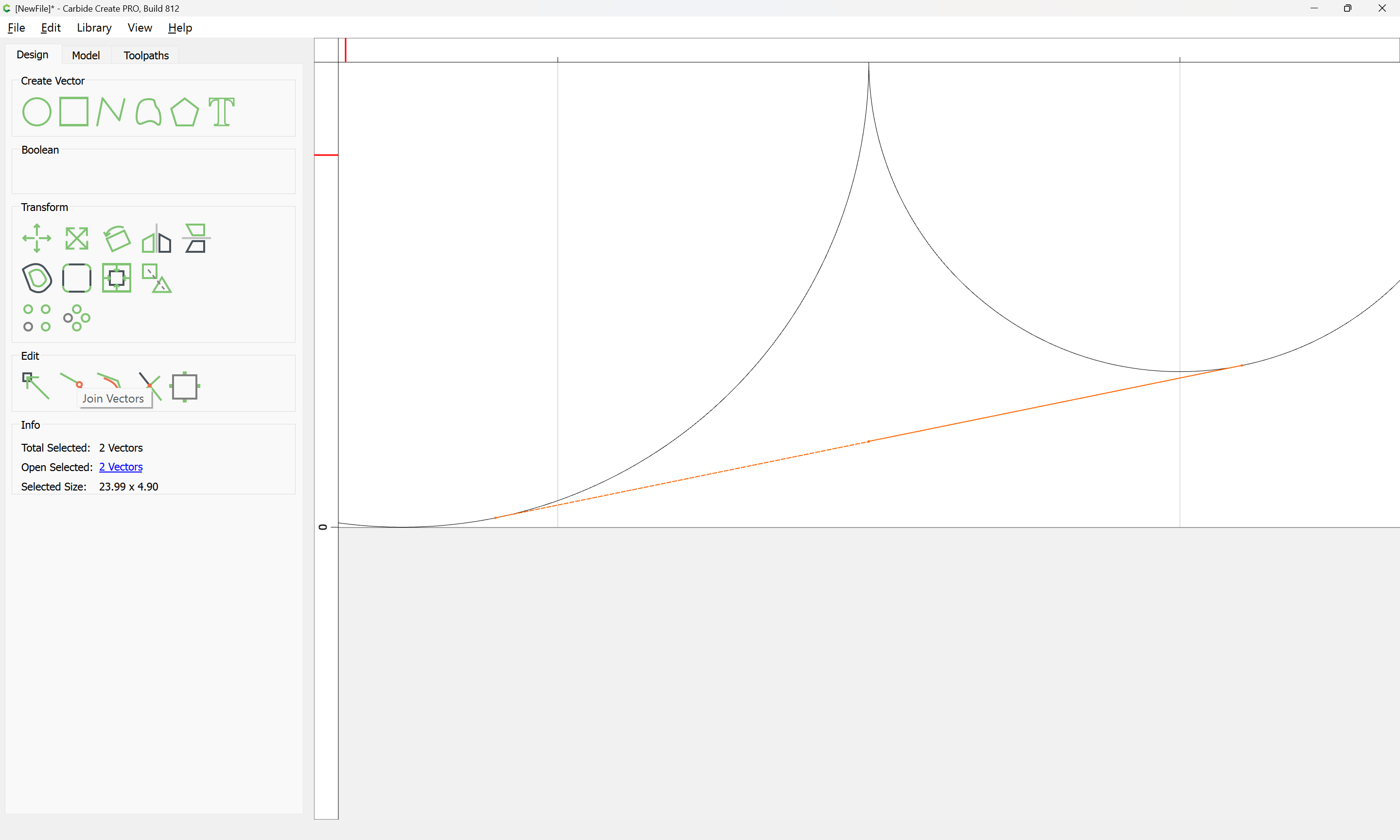
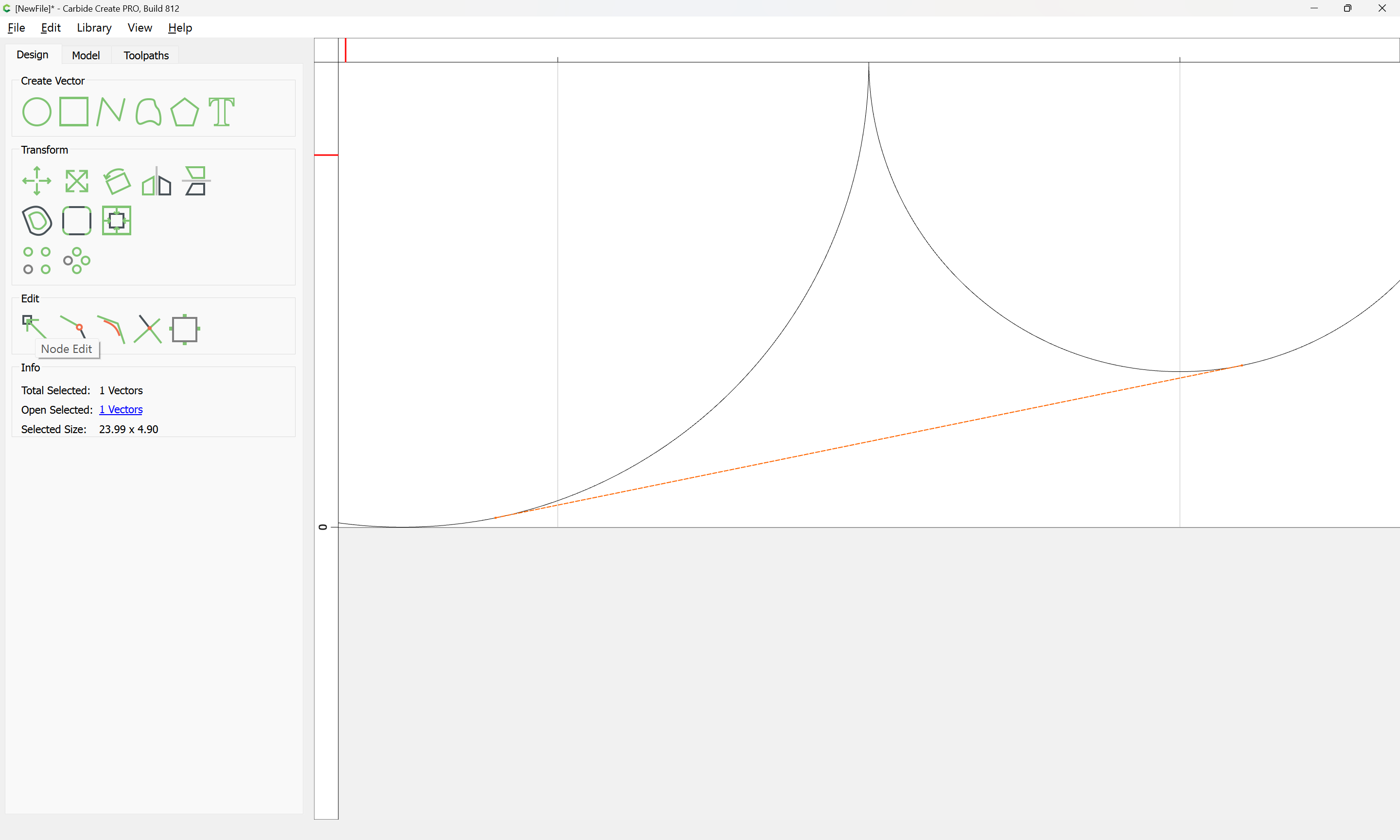
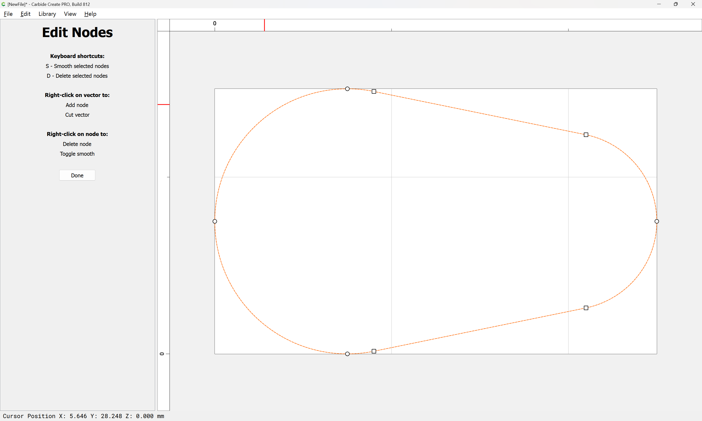
To actually do this by hand so that things line up:

Draw two circles which are positioned as desired:

Draw a line which connects to the larger one and extends past the smaller one:

Duplicate the larger circle, drag the duplicate into position w/ the original and then make it larger than the original:

Select that circle and the line and rotate them:

zooming in and adjusting the rotation until things are positioned as exactly as one wishes:

Done

click to deselect

then click on the line to select it:

go into Node Edit mode:

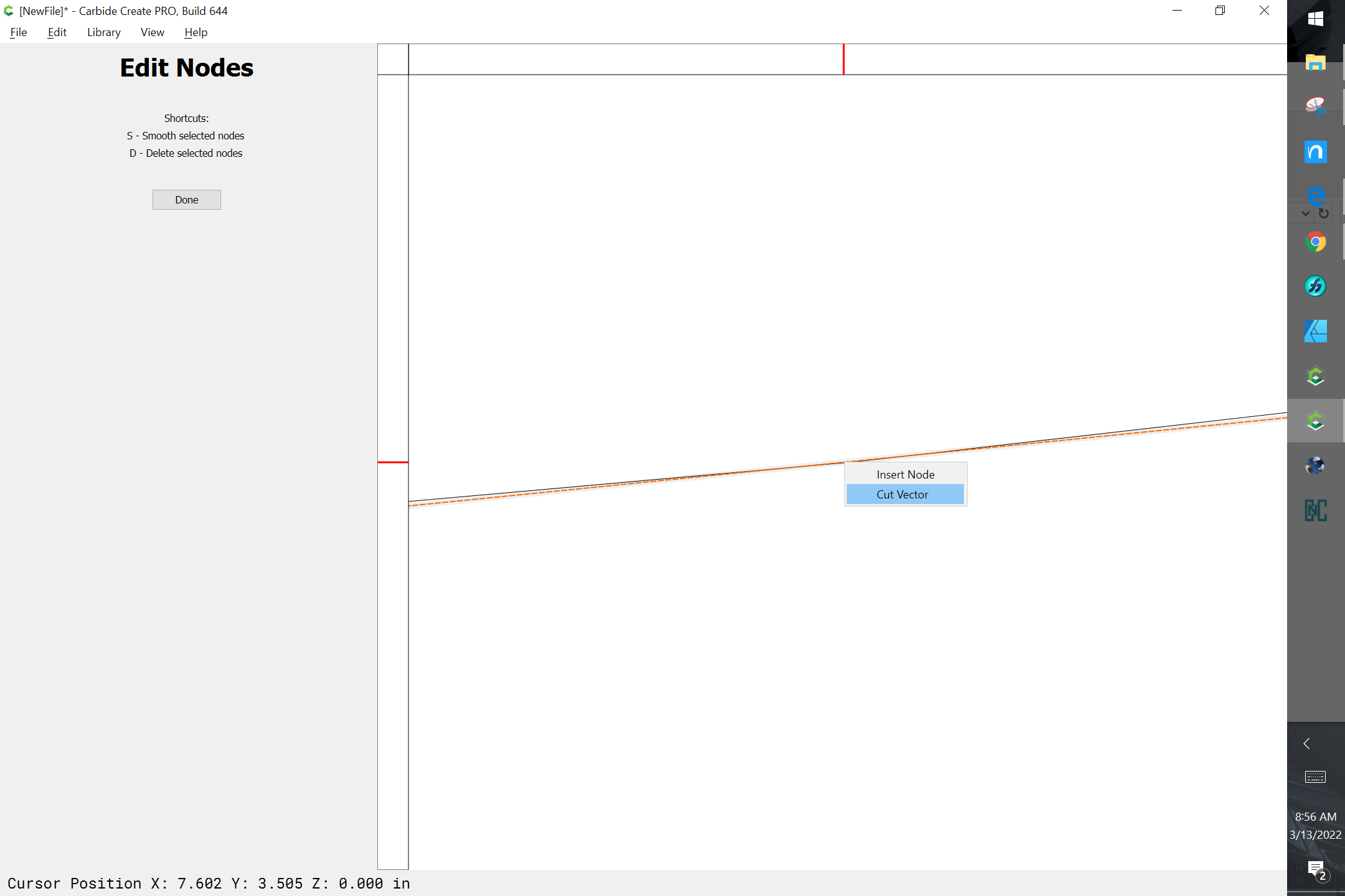
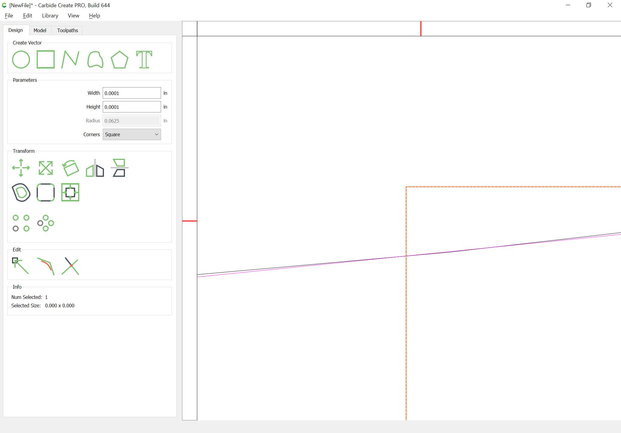
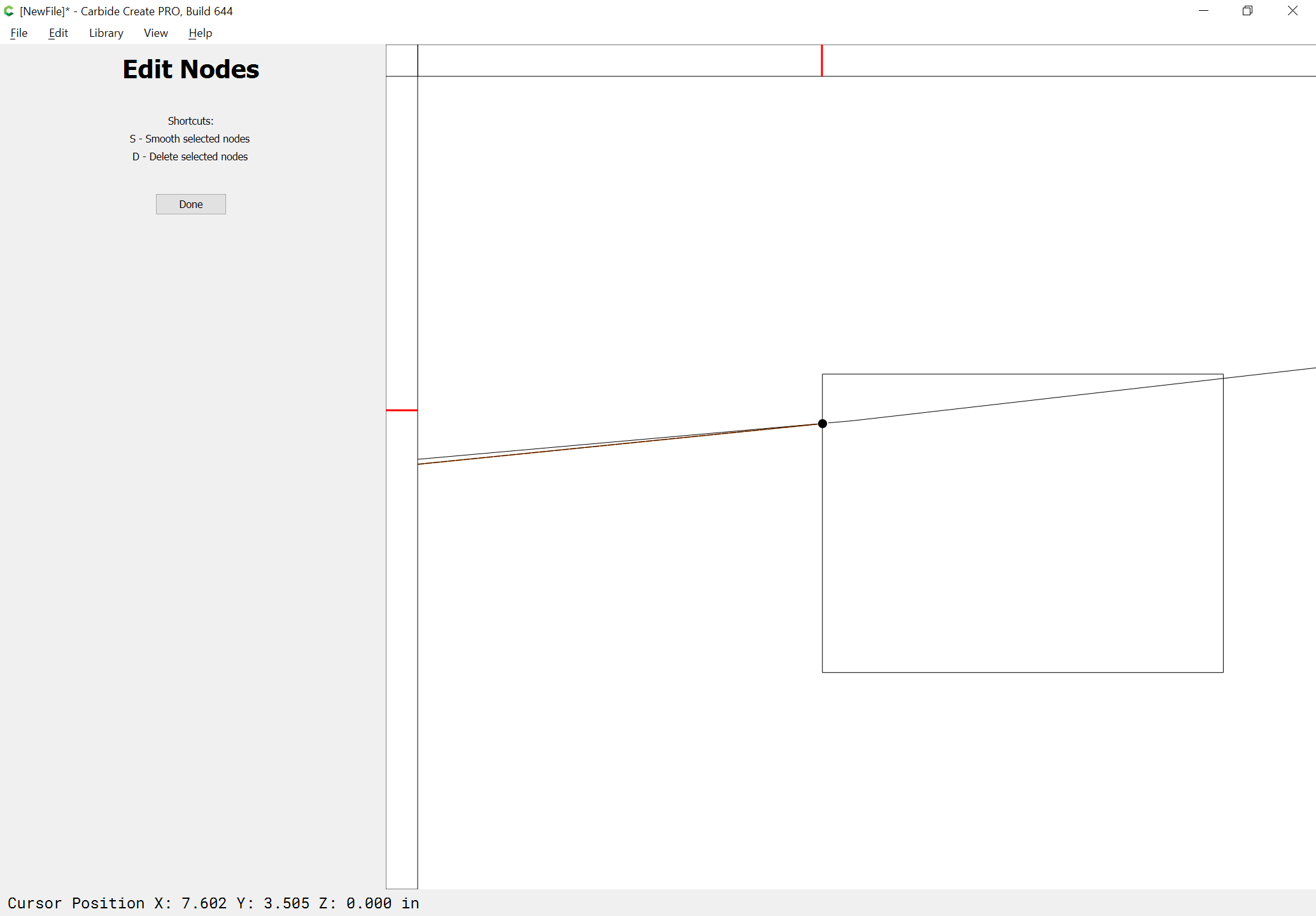
and right-click and choose “Cut Vector” — if you’ve zoomed in so much that the position of the cut vector isn’t visible, draw in some geometry which defines the intersection:

and zoom out a bit after clicking away to deselect and clicking again to select only the one line until one sees the end:

Go back into Node Edit:

drag the end of the cut line into position:

Done

delete the marker graphic and zoom out:

Select and then delete the excess line:

Select everything but the smaller circle:

duplicate and drag the duplicate into alignment w/ the original:

Vertically mirror the duplicate:

draw in lines which connect to the rotated lines and then join the lines, or draw a polyline which snaps to all 4 points:

Select the original circles and the polyline and Boolean Union them:

and delete everything else to arrive at:

Eric, your method & Will’s 2nd method are approximations, eye-balling it. I suspect in many cases this is going to be close enough. But Jim didn’t specify how accurate it needed to be, or what type of job it was.

In other software that calculates the tangent, the result would be “exact” mathematical tangent, within the resolution of the data. NX uses 16 decimal places, I’m not sure what resolution CC uses.

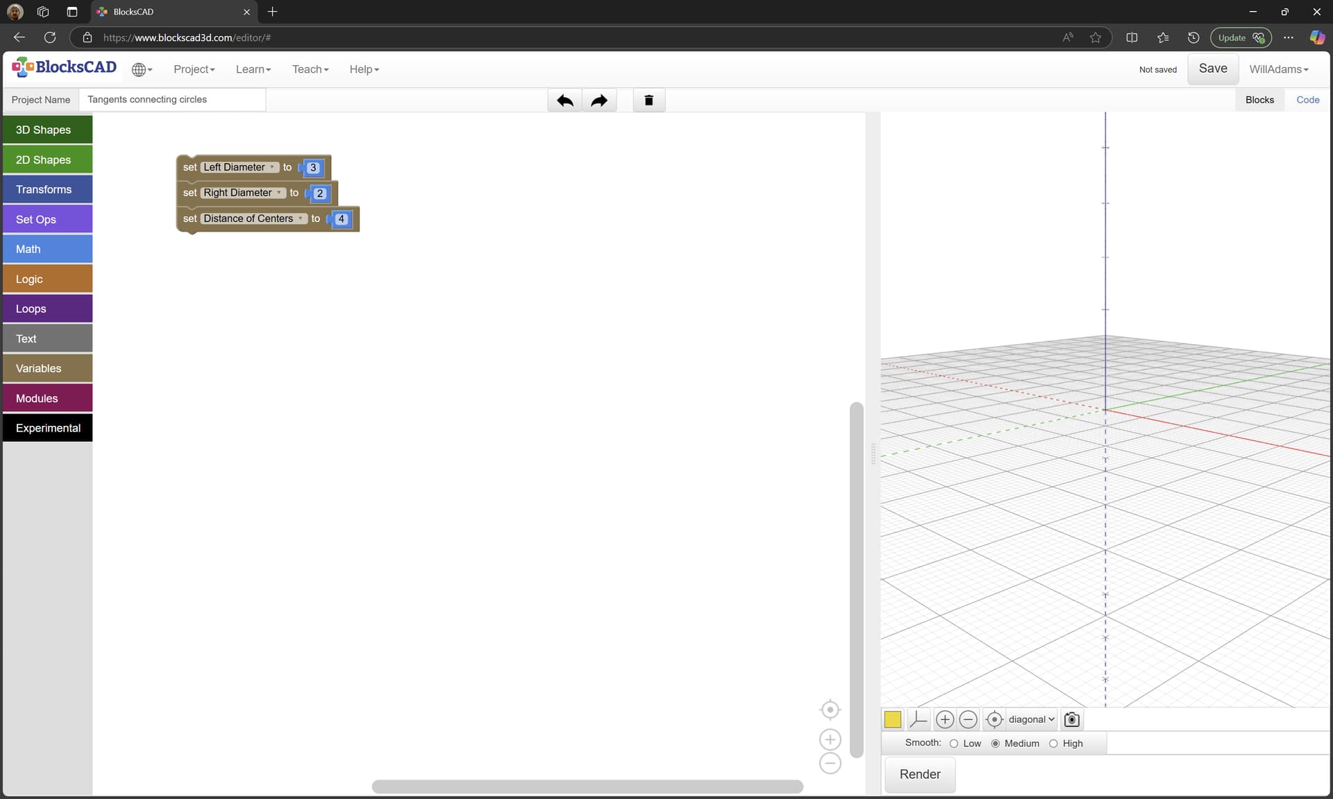
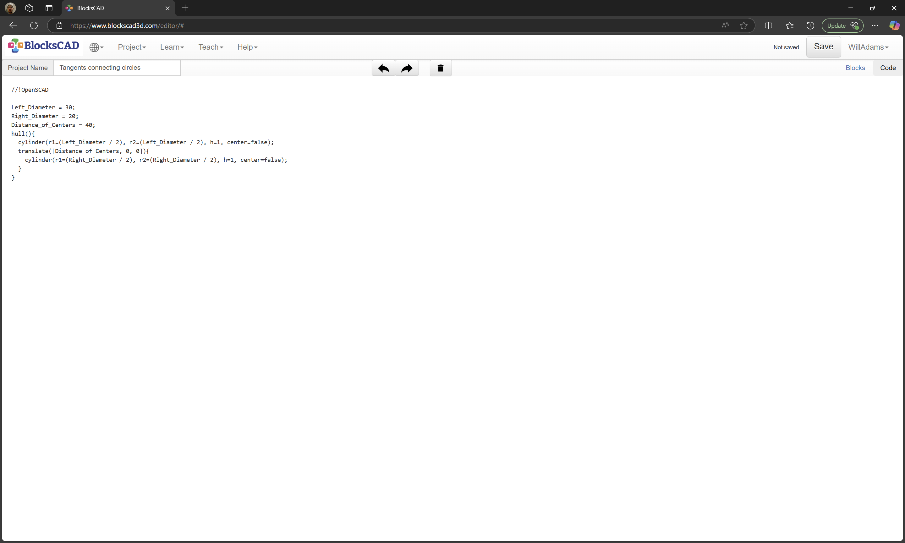
My method & Will’s 1st method will get you as close as you can possibly get with the software.

2 Likes

First, I want to say thanks to Todd for his reply.

Kind of off topic but still related.
Taking the poly line aspect and maybe adding a feature tool, if possible, to take a shape such as what follows.

Maybe have a certain mode to be able to take the short side and using the upper corner node selection then be able to shorten or lengthen the line by moving it up or down, left or right depending on which line you want to change without moving the whole image, this could be a useful feature/tool.

One term for such a command which would work based on drawing two circles is Minkowski or Hull command:

https://wiki.freecadweb.org/OpenSCAD_Minkowski/pl

I don’t believe Minkowski as such would be an option (it’s already covered by the existing behaviour of the Offset command), but a Hull command would be a nice match to “Fillet All”, &c. — put in a feature request, we’ll have to see what folks think.

I probably should have specified further. I was hoping that CC had some sort of tangent function. For my purposes it was more than sufficient to zoom in and approximate the positions of the lines. It only took a few minutes to do and the part came out great.

Excellent! That’s the important bit. :slight_smile:

And the next person that searches for “tangent” has several options to choose from :wink:

This topic was automatically closed after 30 days. New replies are no longer allowed.

Alternately, one can just use BlockSCAD for this directly:

First, create some variables:

and fill in some values:

Then create the first circle (after adjusting the values):

and use a translate command to position the second:

Then use a Hull() command to connect things:

Available at:

https://www.blockscad3d.com/community/projects/1884530

The code may then be copied:

(note that this code has been modified as described below)

//!OpenSCAD

Left_Diameter = 30;
Right_Diameter = 20;
Distance_of_Centers = 40;
$fn = 360;

projection()
{
hull(){
  cylinder(r1=(Left_Diameter / 2), r2=(Left_Diameter / 2), h=1, center=false);
  translate([Distance_of_Centers, 0, 0]){
    cylinder(r1=(Right_Diameter / 2), r2=(Right_Diameter / 2), h=1, center=false);
  }
}
}

and pasted into OpenSCAD:

Adding a variable to improve the quality of the curves/arcs gives us a chance to show the Customizer:

which allows adjusting the values:

Since OpenSCAD is a 3D program, the design may be exported as an STL, or an additional command may be added to flatten it:

which allows exporting as a DXF:

tangent_circles.dxf (10.9 KB)

which may then be imported into Carbide Create:

Alternately, the new Measurement tool in Carbide Create makes this a bit easier:

Measure from Node-to-Node:

Note the angle (11.311) and draw a line:

Select the larger circle and the line:

Rotate

Done

Group

Align Vectors

(twice)

Note that due to the different sizes of the circles things do not line up as one might expect.

Repeat this for the other circle — probably easiest to align the smaller circle at the bottom:

then draw the line:

Then group and re-align:

Rotate the group the same angle:

(note that filling in the center of the circle as the point of rotation will eliminate the need for later re-alignment)

Done

Repeat the rotation for each assembly, filling in the circle center each time with smaller values until the two lines line up:

Done

Done

Ungroup Vectors

While it would be idea if one could just select the two lines and use Trim Vectors, the very shallow angles preclude this, so instead, group them:

Draw a vertical line:

shift-click on the grouped lines to make them the key object:

Align Vectors:

Aligning to the Center:

Ungroup select one of the original lines at a time, and use Trim Vectors to delete the ends which don’t line up:

Ok

Repeat:

OK

Remove the dividing line:

Select the two remaining lines:

Join Vectors:

Node Edit:

Select and delete the central node:

Done

Duplicate the object in place:

Select it and the larger circle:

Mirror Vertical:

Draw in lines which will divide the circles where they meet the tangent lines:

Using the nodes to ensure things line up

Shift-click on the two circles to add them to the selection:

Trim Vectors

Click to remove what is not wanted:

OK

Delete the no longer necessary geometry:

Select everything:

Join Vectors:

Lastly, the question is, why do it thus?

Efficiency of geometry:

If one imports the DXF:

It is made up of many straight lines:

If one zooms in:

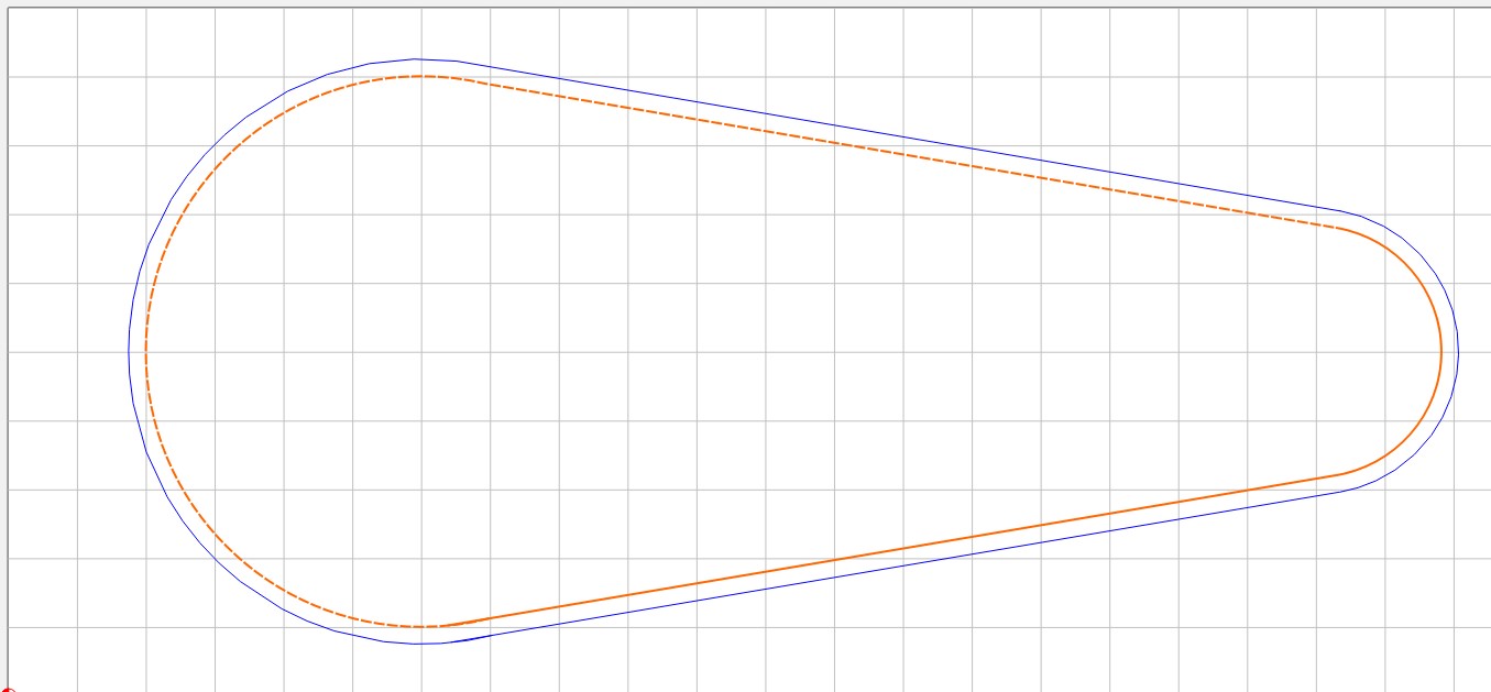
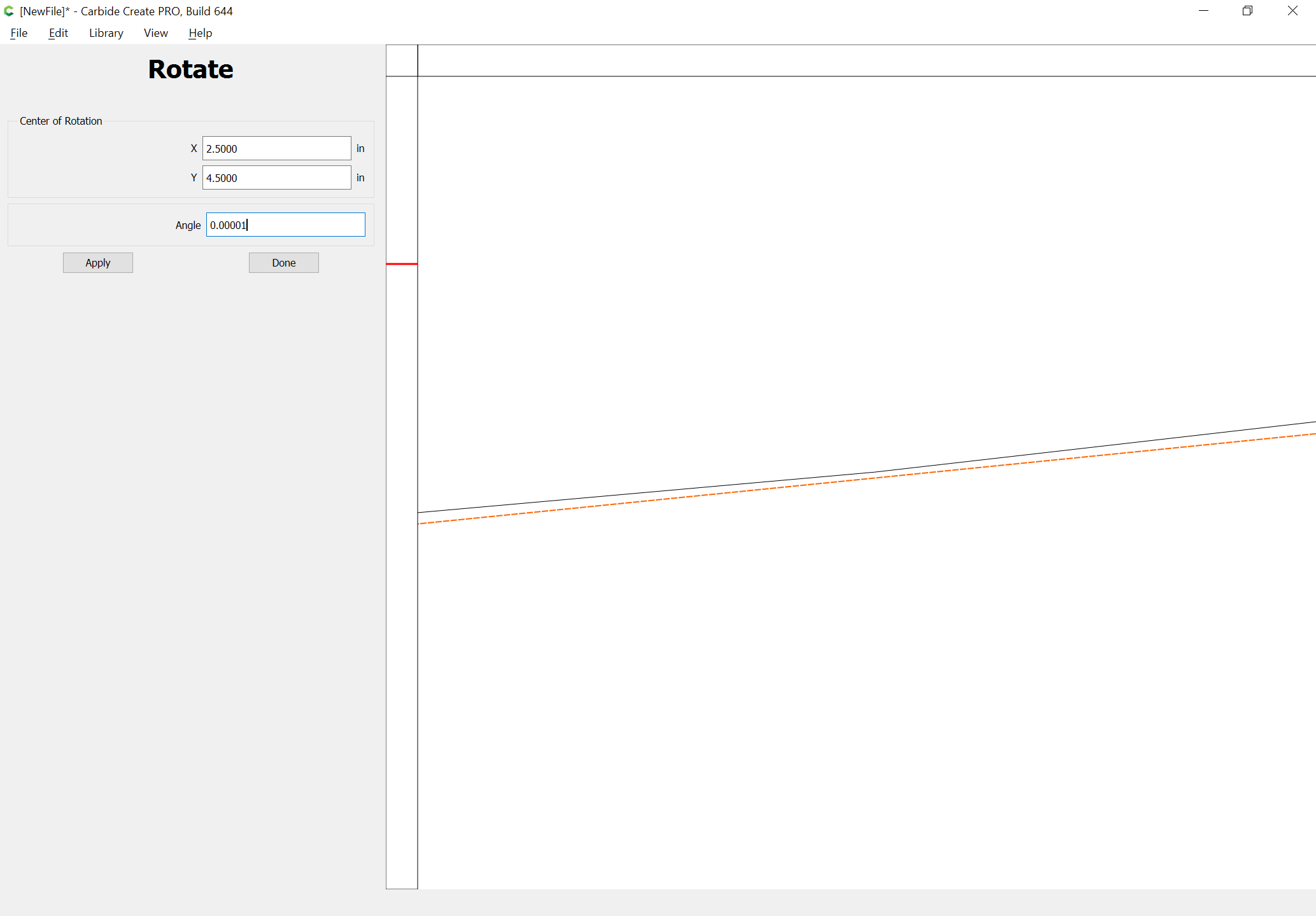
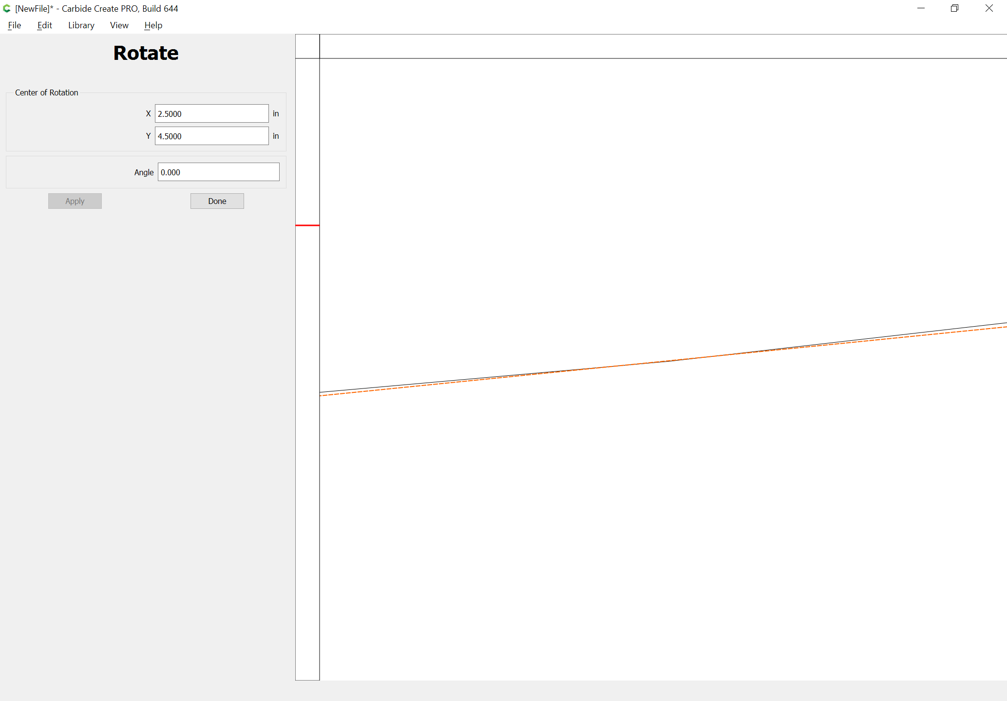
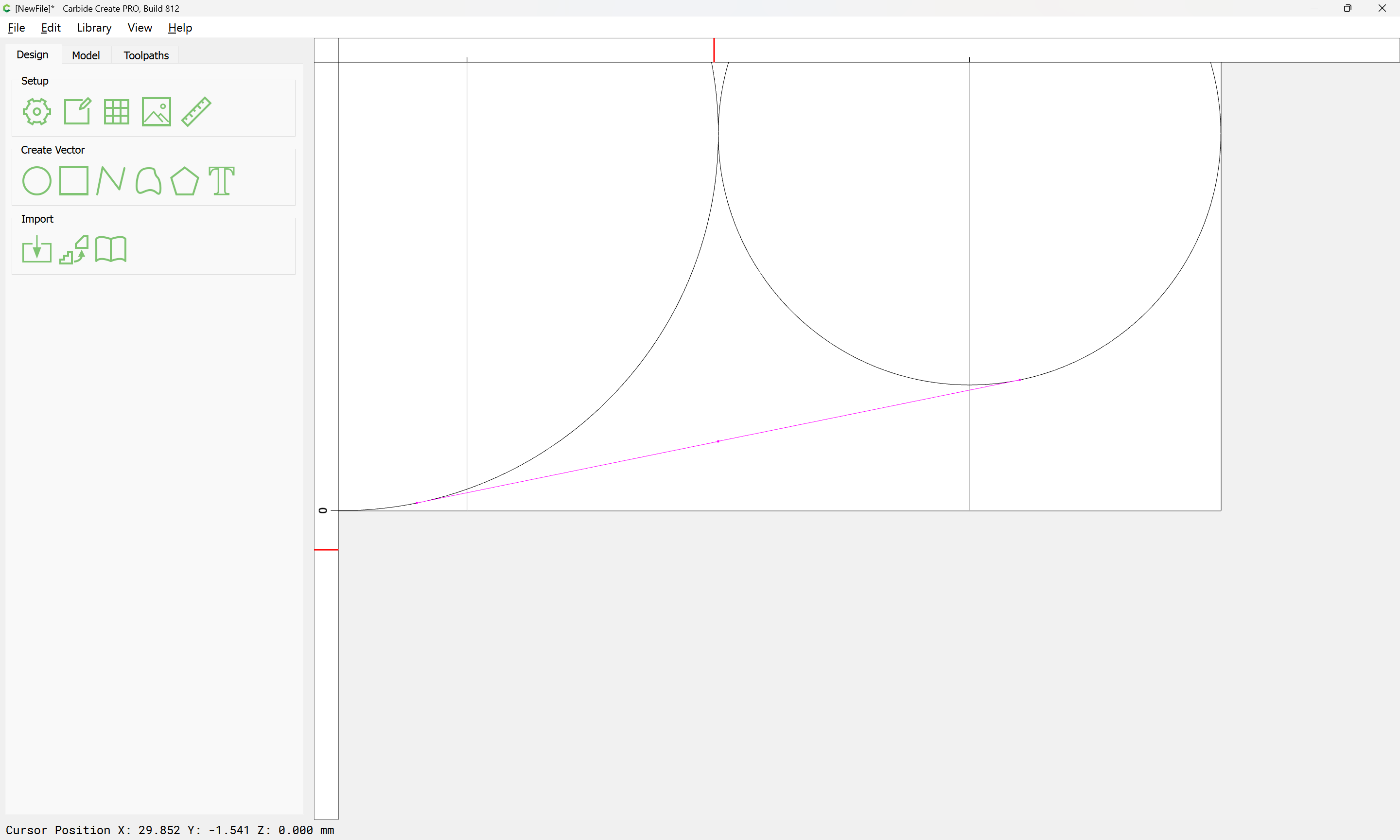
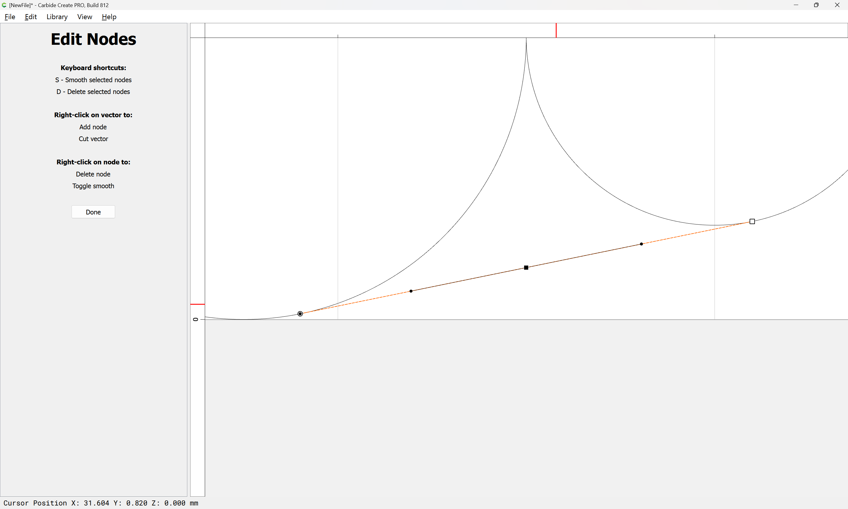
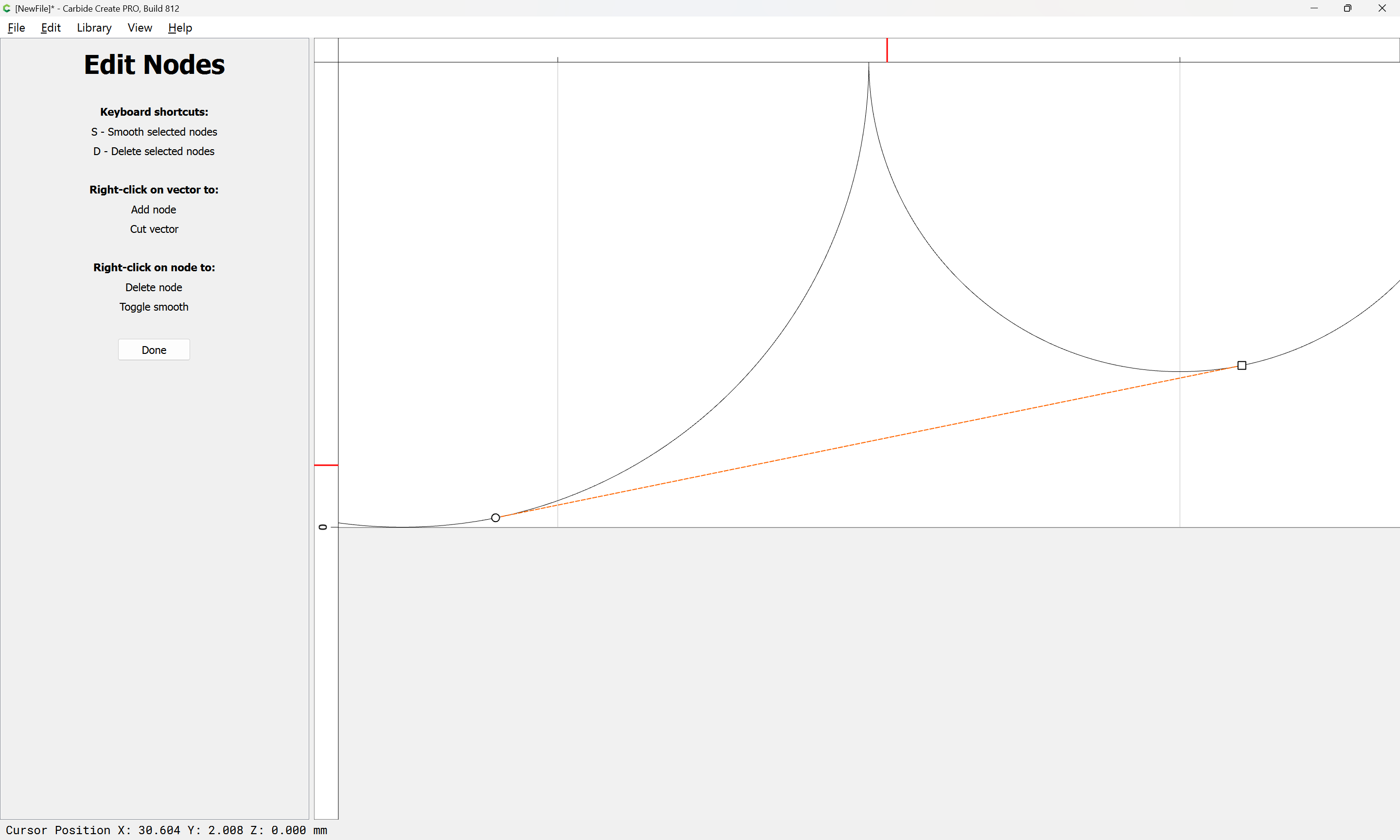
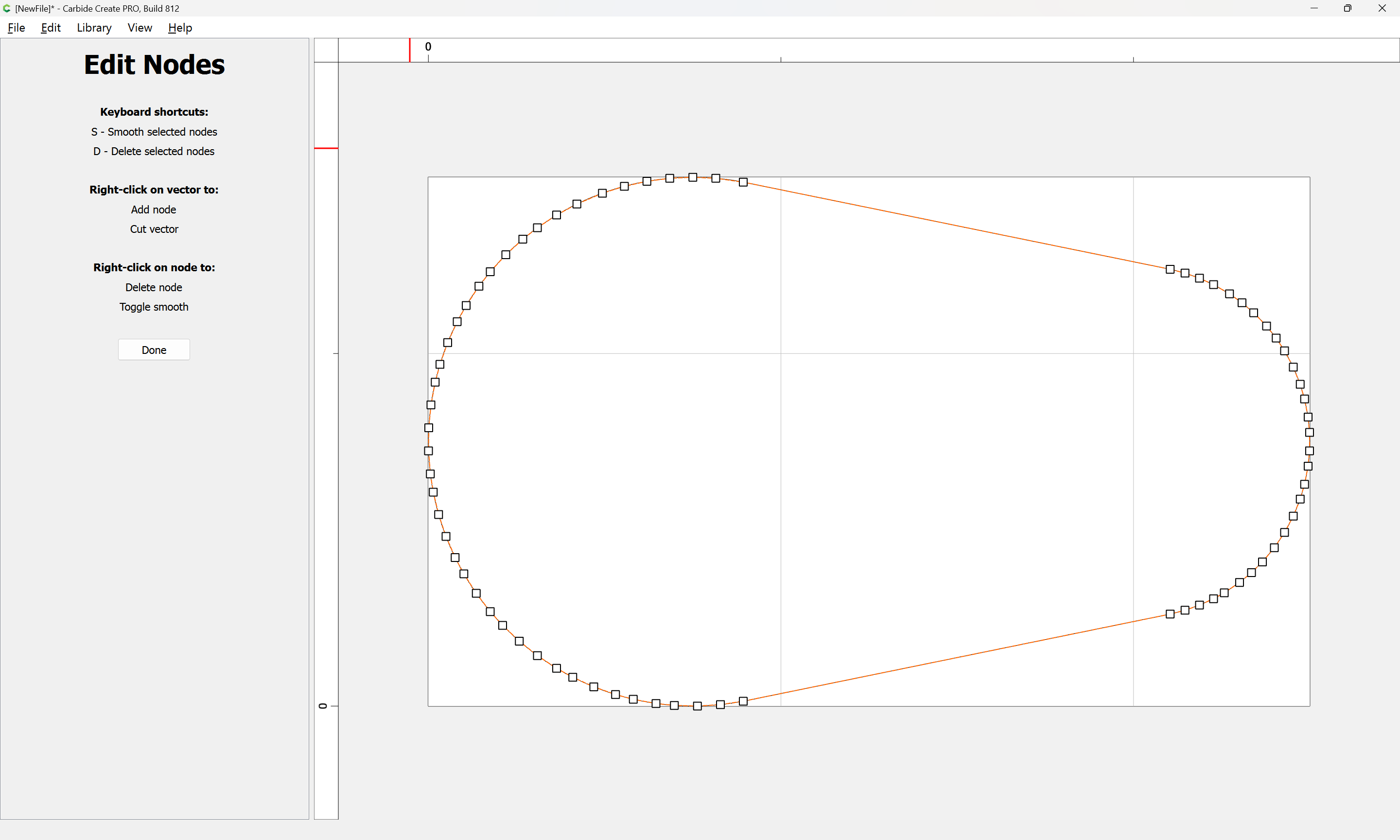
It becomes obvious that the Bézier curve approximation is better than the polyline. Determining how this differs from the actual idealized arc is left as an exercise for the reader.

1 Like