How to do this secret box on a CNC?

Drawing up the design in Carbide Create is pretty workable:

Draw a square for the outline of the box:

Rotate 45 degreees:

Draw up the dovetail tool in profile:

and draw in a rectangle to measure the width of the dovetail slot:

Draw in a square to get the size:

scale by 0.5 to get half:

and reposition:

Select the rectangle for the pocket and align it:

Then increase the size as necessary to cut away completely:

and draw in a straight line along the center:

copy-paste the line and the rectangle into place so as to duplicate them:

Then select the rotated rectangle and flip horizontally:

Draw in the dovetail tool to verify that it will clear:

and if it doesn’t, increase lengths so that it does:

Rotate everything back:

and assign toolpaths:

As noted, you won’t get a correct preview:

You’ll also want to draw in a pocket so that it will serve as a box rather than a puzzle, and add either a ball-catch or magnet.

An elongated pocket increases the storage volume:

Duplicate the file and adjust as necessary to cut the negative of the dovetails so as to make the lid.

1 Like

This topic was automatically closed 30 days after the last reply. New replies are no longer allowed.

Re-worked the BlockSCAD file for this:

https://www.blockscad3d.com/community/projects/1721632

For folks who don’t have OpenSCAD installed it is available at:

https://seasick.github.io/openscad-web-gui/?https://raw.githubusercontent.com/WillAdams/Design_Into_3D/master/openscadwebgui/Impossible_Dovetail_Box.scad

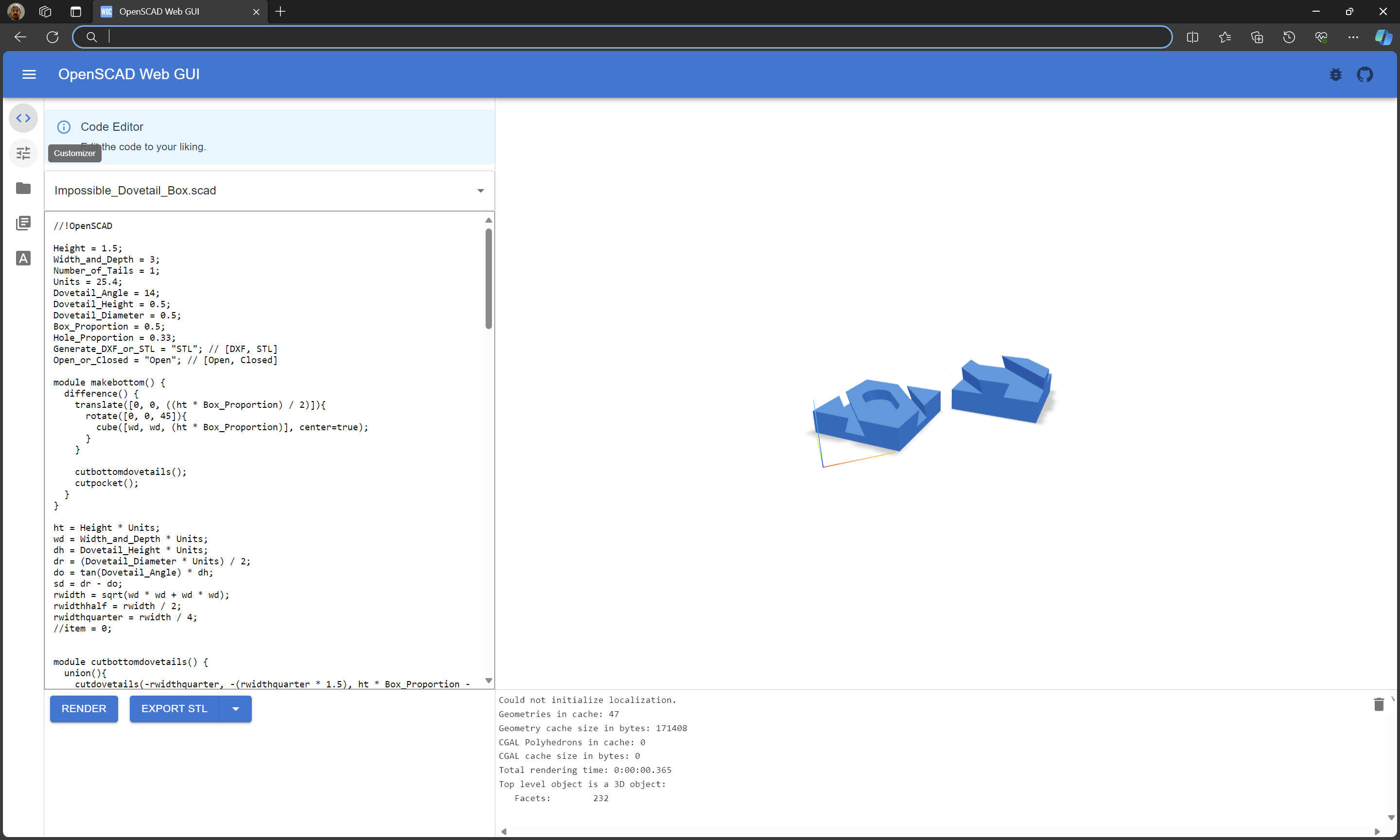
Click on the icon for “Customizer”

to adjust things and choose “DXF” rather than STL to be able to export a DXF or SVG:

EDIT: Note that the image below shows an incorrect construction caused by an error (since corrected) in the OpenSCAD code — adjusting for that error (and finding it in a check of the files) is shown below.

Impossible_Dovetail_Box

which may then be loaded into Carbide Create:

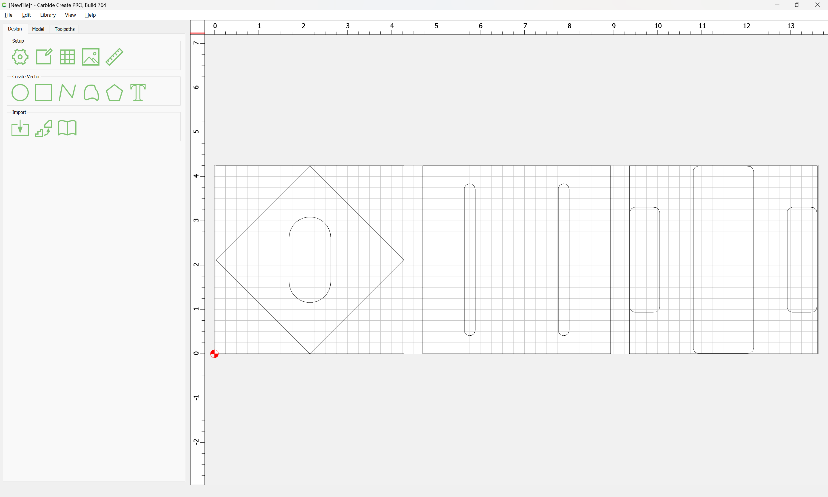
to have toolpaths created.

The geometry will be used as guidelines in creating the geometry and toolpaths needed to actually cut out the design.

The actual box outline will be rotated 45 degrees:

to make it easier to arrange the stock on the machine to cut — the other elements will be brought into alignment with it.

Done

Since Carbide Create cannot show undercuts in the 3D preview, we will draw up the Dovetail tool in profile, and use a proxy circle for it to check at need.

The basics of the box are quite straightforward:

as per usual we offset to the outside by tool diameter plus 10%:

and cut that and the pocket to suitable depths:

Next we need geometry and toolpaths for cutting the dovetail slots for the bottom:

We draw a circle the same diameter as the geometry for the dovetail slots:

and duplicate it and align a copy at each end of a slot:

and draw a line from center-to-center:

duplicate it in place, and select it and the outline and use Mirror Horizontal to move the copy to the other side:

Check that the lines are far enough from the box outline by dragging the drawing of the dovetail tool over:

Then assign a pair of toolpaths, one to clear the slots w/ a suitable square endmill, the other to cut the dovetails with the dovetail cutter:

Next duplicate the circles and the lines drawn for the dovetail tool and adapt them to cut out the dovetails for the top:

Offset the outline of the outline of the top:

and then select it and the pockets:

and use the Trim Vectors tool to create optimal geometry for removing the bulk of the material for the top:

arriving at:

OK

OK

which may then be joined together:

Yes

Additionally all of the circles for the entry/exit points for the Dovetail tool should be instantiated at that tool’s diameter:

and unioned with the pocket toolpaths so that as much material as is possible will be removed before the Dovetail tool cuts:

It is then possible to rotate the Dovetail slots for the bottom and move them into register with the pockets for the bottom:

and to repeat the process for the top:

at which point the file may be saved and the duplicated to make separate files w/ appropriate thickness for top/bottom.

Thinking on this overnight, a better thought than using the No-offset contour w/ the open geometry would be to just put in circles at the origin:

and then use those with a Keyhole toolpath with the appropriate settings:

It is just necessary to work out the requisite length (and angle).

I think I would start with a straight end mill no wider than the narrow end of the dovetail bit to remove as much material as possible in less than full depth passes.

1 Like

Yes, that is mentioned above (but apparently not made very clear).

Reworking the design to take the use of the Keyhole toolpath into consideration we have:

One further improvement will be to chamfer the corners (we will also do this to the top/bottom after machining).

Lastly we will save in two separate files, for the bottom and lid, and adjust the thickness for the latter.

Sorry, I missed that. I should read more carefully.

1 Like

Before committing to separating the top and bottom as two discrete files, we verify the design by working out what the cut will look like in profile:

Increase the size of the surrounding geometry so that it projects beyond the other outlines:

Rotate each -45 degrees:

Done

Remove the unneeded outlines:

Shift things up a bit to make room for the profiles:

and draw in rectangles:

Align an outline of the dovetail tool with the profile:

Select the feature which it will be matched with and use Align:

to move it into position.

Repeat for the others:

Boolean subtract each (or use Trim Vectors):

Draw in geometry to match the pockets which will be cut to either side of the dovetails on the lid:

and align it with the bottom of the dovetail cut:

Boolean subtract it as well:

Repeat until one arrives at:

Duplicate the lid, rotate it 180 degrees and check the fit/match:

and apparently the dovetail toolpaths need to be shifted a bit…

This much:

hang on while some adjustments are made…

Eventually we arrive at:

which passes muster and is okay to go on with separating into two files (once we chamfer the corners)

1 Like

To keep this simple, we’ll do one piece of stock and centered as shown above:

First step is preparing the stock — the piece I have in mind is rough-cut, so there will be a bit of prep-work, probably a separate post.

Or, maybe it’s easier to match the stock as clamped in place:

One other touch is pockets for magnets:

Hopefully final version:

Take 2

Impossible_Dovetail_Box_v7.c2d (132 KB)

Note on tooling — the last toolpath in the above uses a #102, but this needs to be a long reach tool, in this case a Garr Tool Series 620MEDP#41030 1/8"x3x1"

https://www.garrtool.com/product-details/?EDP=41030

The dovetail tool used is apparently discontinued, but was still available on Amazon:

https://www.amazon.com/Freud-Dia-Dovetail-Shank-22-104/dp/B00002241Z

Note on workholding — belt and suspenders will be needed here — you’ll want an adhesive workholding system holding the parts in place, or you’ll need to add tabs, or you’ll have to do as I did, and halt the cut short of the bottom and cut the parts free by hand.

And success

Note that with an onion-skin, one can hold things up to a light (or use a lightbox) to determine where to cut:

except for a bit of post-processing and installing magnets and finishing:

A couple of minute’s work w/ a file and plane:

7 Likes

and a bit of sanding and gluing magnets and we have a product which just wants a finish (probably just oil and beeswax)

8 Likes

Project post-mortem:

There was some tearout (as can be seen in the photos), and some uneven tool alignment — leave a roughing clearance for final passes — recommended tooling for final passes:

  • the dovetail tool — add additional passes w/ it using the keyhole tool so that it cuts the bottom of the entirety of the underside of the lid
  • a sharper tool for the sides — need to find a long-reach 1/8" downcut

Another possibility is just cutting it to final dimensions after putting in the magnets, cutting it to final dimensions/shape on my Jointmaker Pro:

3 Likes