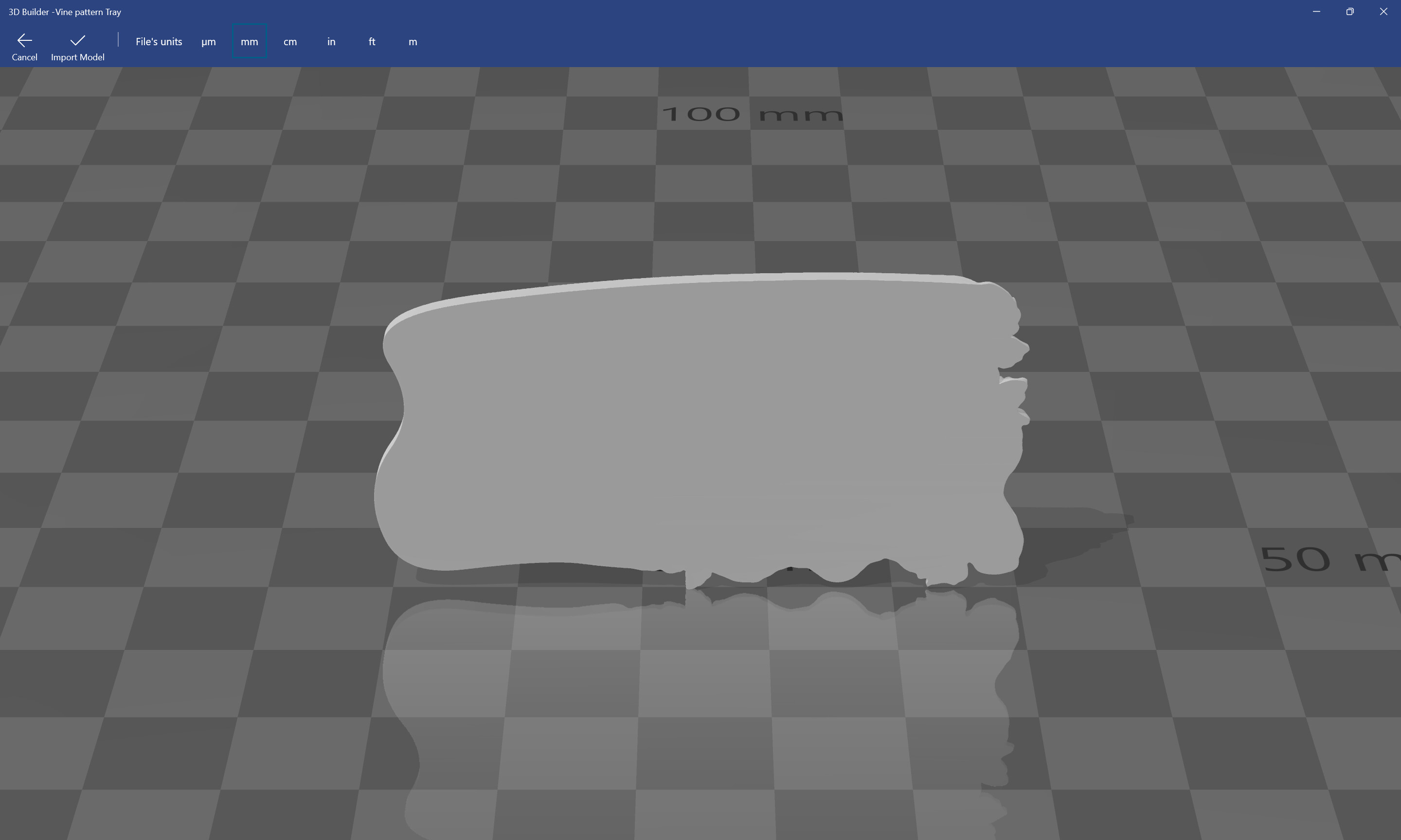
Will, can you measure the STL in 3D builder? I open all my STLs in NX & add a “Bounding Box” which tells me the overall dimensions. Then I find the lowest spot on the contoured portion & measure the depth from the top, so I know how much base height is already built into the STL.
If I don’t want that much base height in my project, I set the stock size in CC to something larger, subtracting the difference from my actual stock.
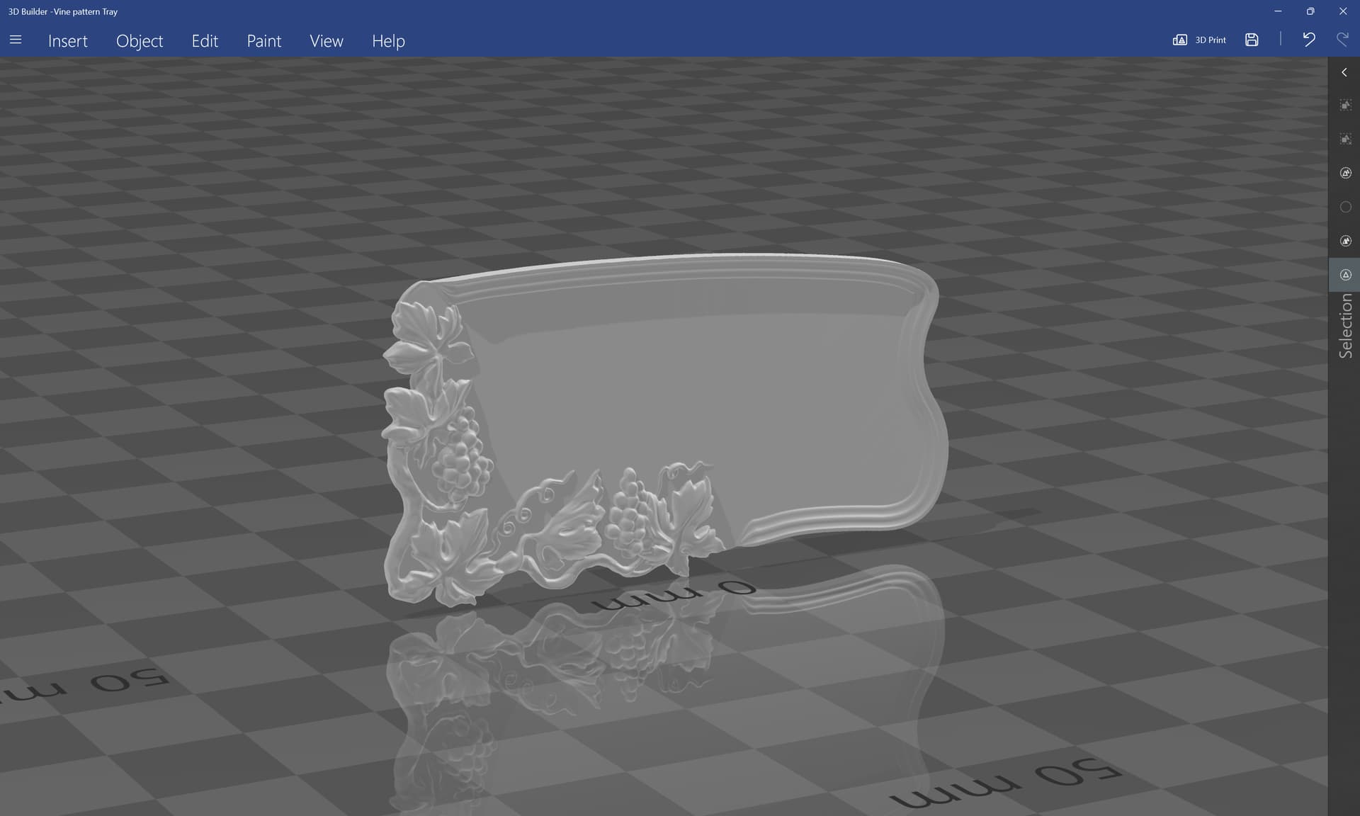
That model looks to be about 1/2" tall, with a 1/4" base. So only the top 1/2" is the contoured detail.
To carve this into a 3/8" board, I would set the stock height to 1/2". Then when I carve 1/4" deep it leaves 1/8" as my base on the actual job.
Probably there’s a measurement tool as well, but they changed the UI from the initial quite nice, consistent and intuitive one, so I don’t use beyond opening, repairing and so forth.
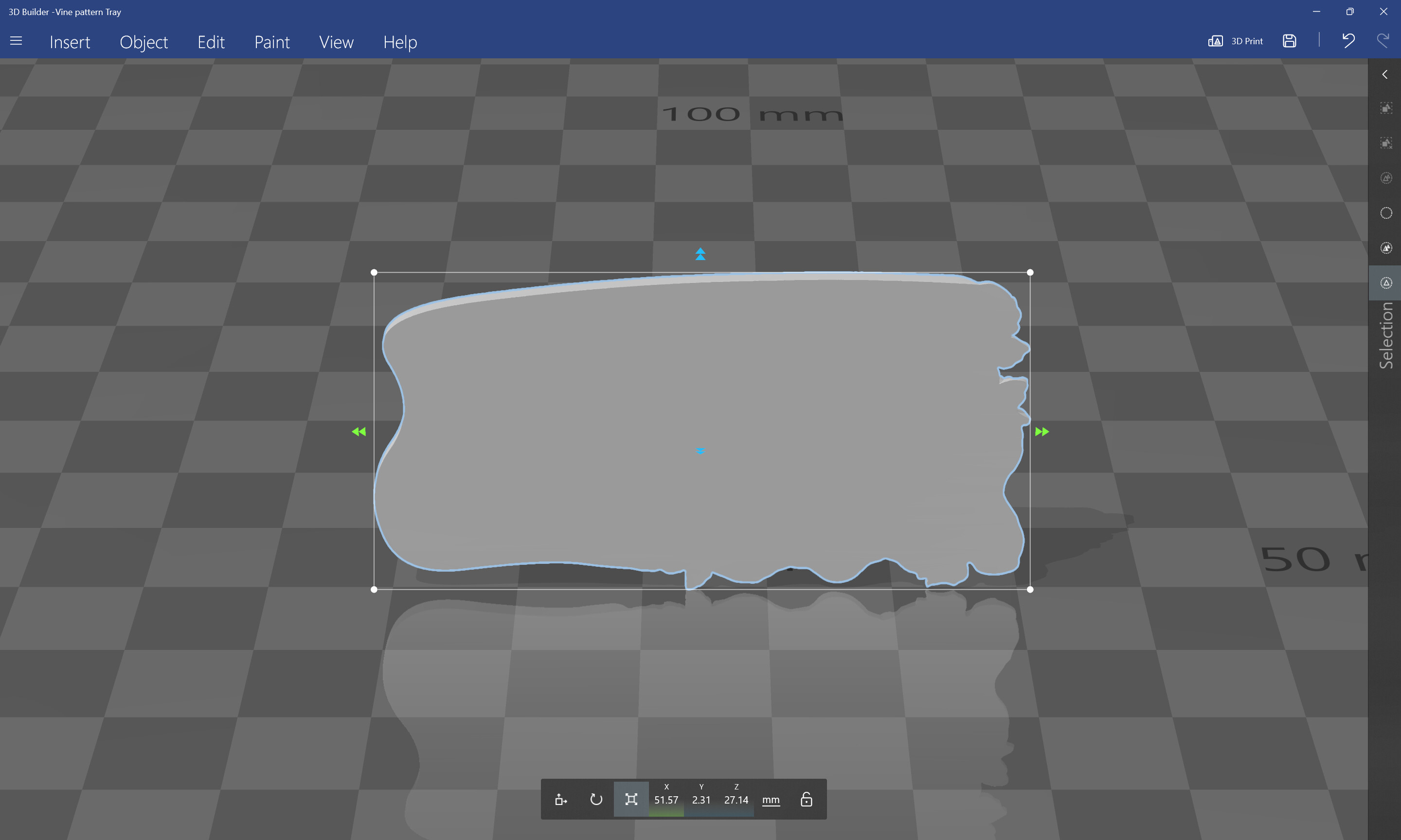
Ah, OK. So 2.31 mm is 0.090". And about half of that is base, with the detail being the top 0.045. (maybe 0.040??)
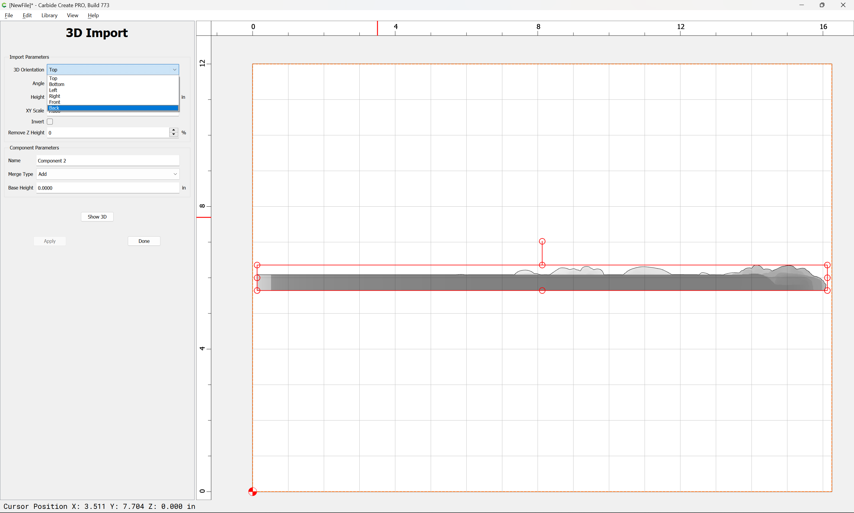
So to carve the detail 0.650 deep on a 1.125 stock, He would want to set his stock height in CC at 1.3", and import the STL at 1.3" height.
It would be a good idea to create a flat component larger than the part at 0.175 thick to prevent the cutter from rolling off the edge of the model & cutting 1.3" deep, and into the table since the actual stock is only 1.125. (3D paths don’t have a Max Depth)