nonon
August 25, 2023, 12:18pm
1
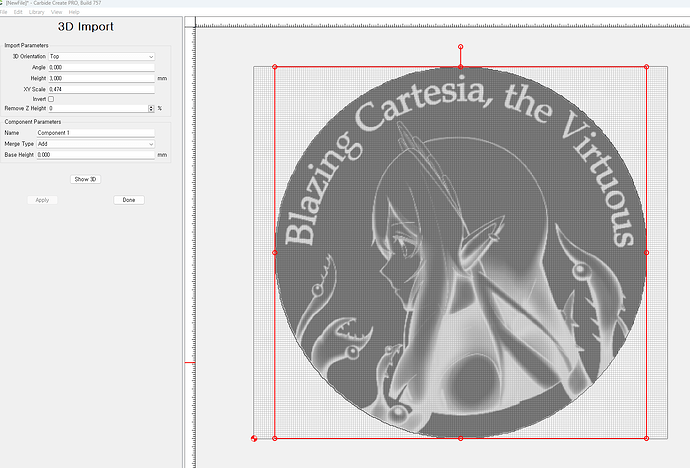
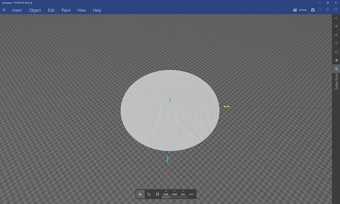
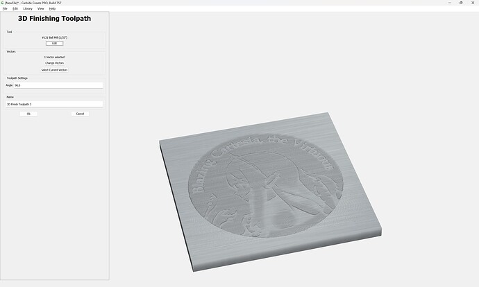
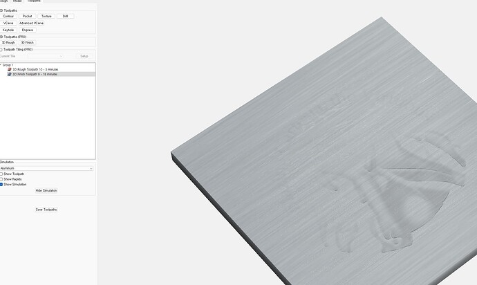
first, i imprt my 3d stl file.
i thought that looks cool.
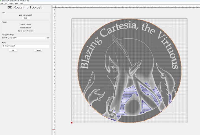
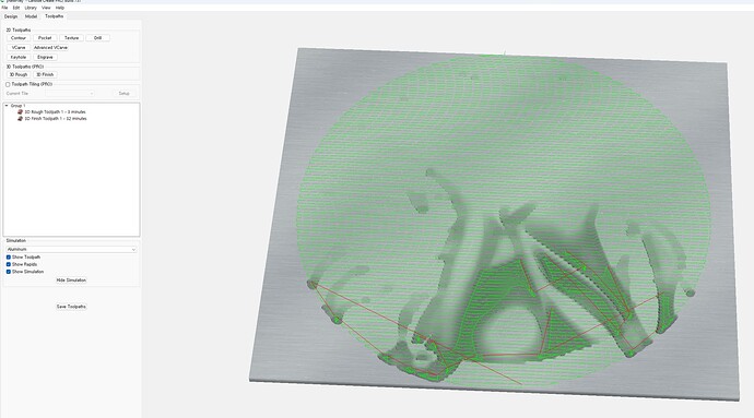
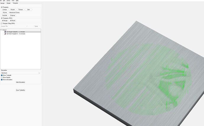
i try rough 3d and
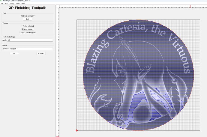
did finish 3d.
but expect result is very bad.
It’s a completely different result compared to when I saw the imported image in advance.
Is there a tutorial or video that I can get help with on this? I’m at a loss.
WillAdams
August 25, 2023, 12:49pm
2
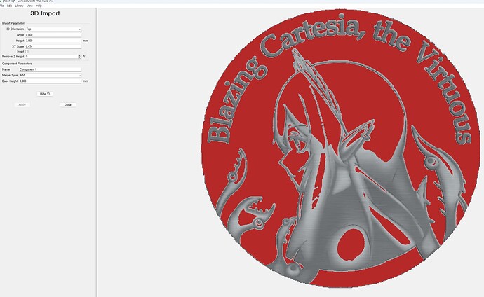
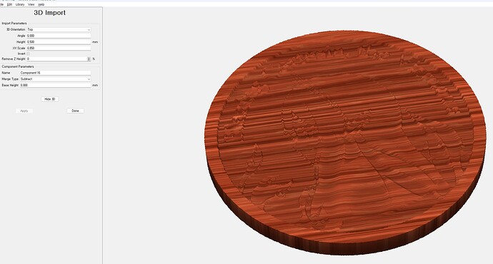
The red indicates that you are raising the model up above the Stock thickness.
I suspect you may want to invert the image.
Could you post your files? Both .c2d and .stl? (send them to projects@carbide3d.com if not suited for sharing)
nonon
August 25, 2023, 1:03pm
3
I invert it, but the result was not much different. i sent stl file to ur email. thx for taking time for me
Let us know how this turns out, looks really interesting
1 Like
WillAdams
August 25, 2023, 10:27pm
5
The file seems quite physically small, and does not seem to have much in the way of Z variation:
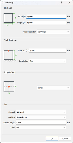
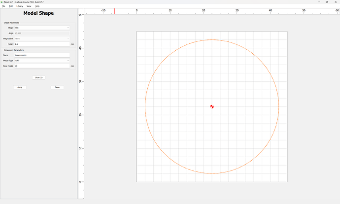
Checking on Amazon most coin blanks seem to be 40mm in diameter and 2.5mm thick, so we set up the file for that:
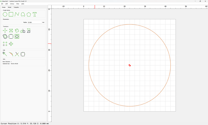
We then draw in a circle for the blank:
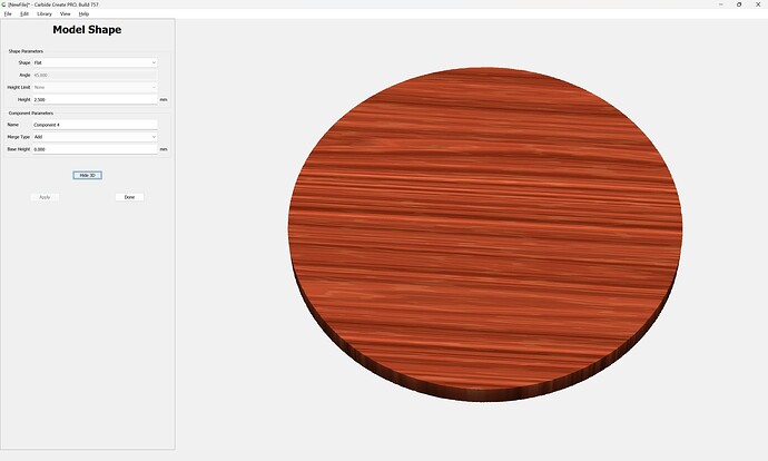
Model the stock:
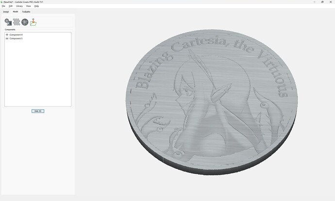
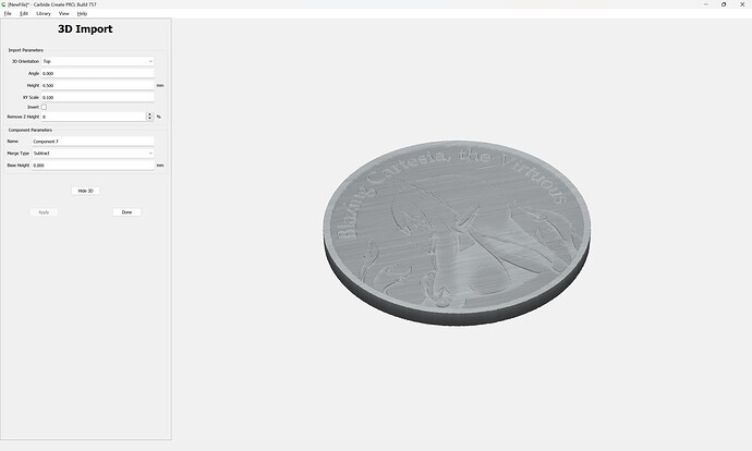
and import the STL:
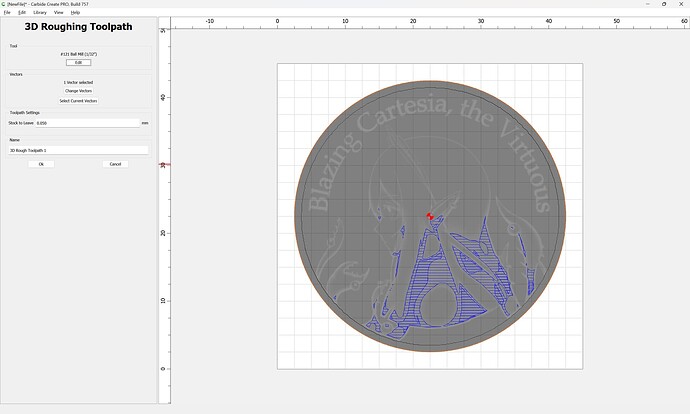
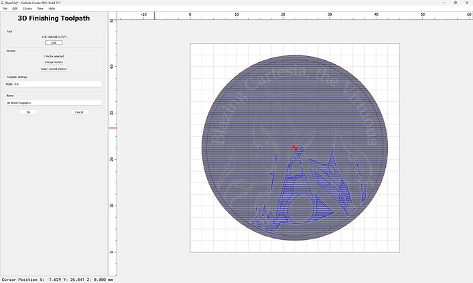
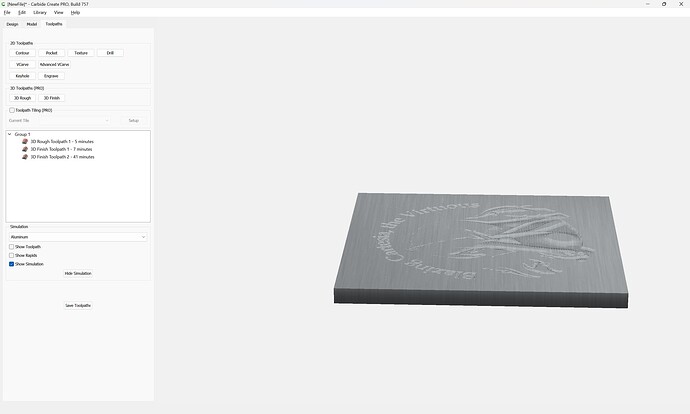
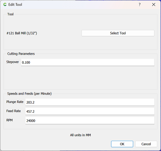
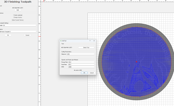
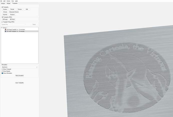
We then apply 3D roughing and finishing toolpaths using suitable small tools:
If you create an impossibly small tool you can get:
Subtracting the STL we instead get:
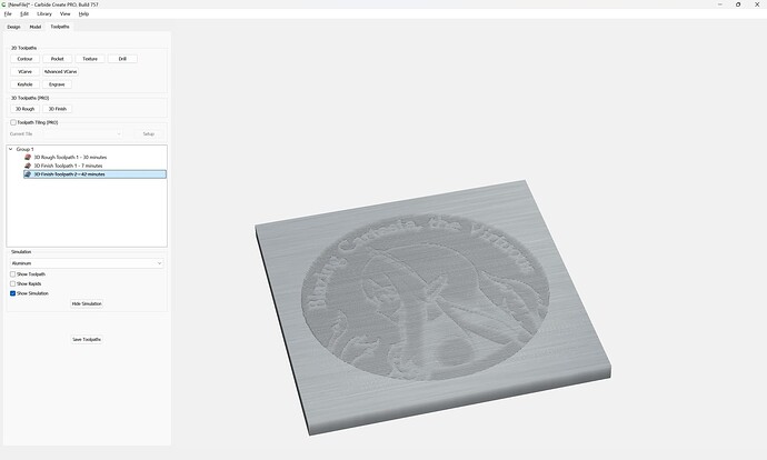
which previews as:
Adding more 3D Finishing toolpaths and increasing stepover gets us to:
nonon
August 25, 2023, 10:38pm
6
Thanks to you, I understood more about how to apply the stl file. Very kind and detailed! thx a lot. I’ll update you when the results come out
nonon
August 26, 2023, 9:54am
7
hi! i did modeling with ur screen shot. but simulated result is very different. can i know the problem? // i find ur third toolpath. what is that?
WillAdams
August 26, 2023, 1:05pm
8
I posted the screen grabs above with my specific settings — please try those.
The disabled toolpath was a test w/ an impossibly small tool to see how the initial 3D model would cut.
nonon
August 26, 2023, 2:10pm
9
where can i saw ur post? I did it the same as the setting you sent me above. I sent you a video of my process by email. Could you check it out?
WillAdams
August 26, 2023, 2:30pm
10
As noted above, the stepover was adjusted.
nonon
August 26, 2023, 2:35pm
11
the result has slight changed. but still bad .
WillAdams
August 26, 2023, 2:36pm
12
I believe I had better luck subtracting the STL from the design — see the screen grabs in my post above.
nonon
August 27, 2023, 7:18am
13
I made a simulation with subtracting. It’s better than before, but it’s not clear, what do you think
WillAdams
August 27, 2023, 2:11pm
14
This may become clearer with smaller tooling which can cut better details.
Or, perhaps you could get, or make a better 3D model.
Or, perhaps you could re-draw some of the design in Carbide Create so as to better cut the details.
nonon
August 27, 2023, 2:23pm
15
i see. but i use same tool #121 and same design file. but simulated result is quite different. i don’t know what is different
WillAdams
August 27, 2023, 2:30pm
16
Cutting a design into a surface (incised) and cutting a design away from a surface (bas relief) are quite different things, and the same tool used for each may have different results depending on the specifics of the details.
nonon
August 27, 2023, 2:42pm
17
Can I follow ur detailed settings? I copied the images you sent me, but there must be something else. I’m sorry I took up too much of your time.
WillAdams
August 27, 2023, 2:48pm
18
Yes, I posted screen grabs of every step I went through in making the file which I sent to you — one thing which I would suggest is to copy into the component name all of the settings used for a given component — that should allow experimentation, and evaluation of how one setting differs from another.
I wrote a little bit about Carbide Create Pro’s 3D modeling at:
which will hopefully be helpful.
And there are of course the videos at:
https://my.carbide3d.com/#Carbide_Create_Pro
If you need more, I would suggest signing up for a training class:
Whether you're a beginner or an experienced craftsman, this personalized training experience will accelerate your skills and understanding of your Nomad or Shapeoko and its associated software. Dive into the world of Carbide Create design software,...
Price: USD 30.00
1 Like
system
September 24, 2023, 12:18pm
20
This topic was automatically closed after 30 days. New replies are no longer allowed.
