If one wants to make drawers which are:
21.846" wide, 18" deep, 10" high
out of:
1/2" Baltic Birch
using a:
1/4 compression bit
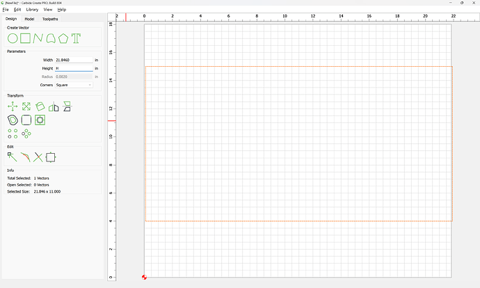
One approach would be:
which gives us the overall dimensions along X and Y.
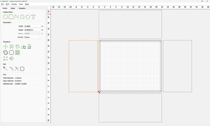
We then draw in the sides, front, and back as seen from overhead:
and then select the original geometry:
and subtract the Stock Thickness from the Width and Height:
which gives us the dimensions of the bottom.
Then, draw in the profiles of the sides, front, and back:
and draw in a vertical view of the joinery:
and adjust the size of the sides to match that size:
Dupe the sides and re-size them to match the extent of the material left behind by the rabbet:
and draw in the geometry for the rabbets:
Since the tool being used is the same dimension as the desired rabbet, draw in lines:
and position them at the center of each rectangle which demarcates the rabbet:
using Align:
It will also be necessary to draw in geometry which defines the grooves for the bottom:
Note that there are two ways to handle this — just cut the groove as a pocket, or use it to delineate two separate islands which will be left proud — we will do the latter:
OK
Done
Next, arrange all the parts on a sheet:
delete the unneeded geometry:
and re-arrange parts for a reasonably efficient usage of the sheet, being careful to position the pieces separated by at least endmill diameter plus 10%.
(if desired, flip parts for a consistent placement which will make workholding easier and may make cutting more efficient)
Select all the geometry which defines the parts:
and offset by endmill diameter plus 10%:
Apply
At this point, toolpaths may be applied:
Select the open geometry:
and apply a No Offset Contour toolpath to half the thickness:
Then select all the geometry which defines the interior surfaces of the drawer as well as the surrounding offset geometry:
and assign a Pocket toolpath to half the depth:
Then select the geometry which defines the perimeter of all the parts and the surrounding offset geometry:
and assign a pocket toolpath which starts at the bottom of the previous pocket and cuts down to tab height:
Go back to the Design tab, and remove the outer offset geometry from the selection:
and edit tabs:
adding a reasonable number of tabs, being careful to align them where necessary so that opposing parts will have tabs in the same location:
Note that it will be necessary to zoom in to place the second of a pair of tabs:
Assign an Outside Contour toolpath which starts at the bottom of the previous pocket:
Verifying the 3D preview:
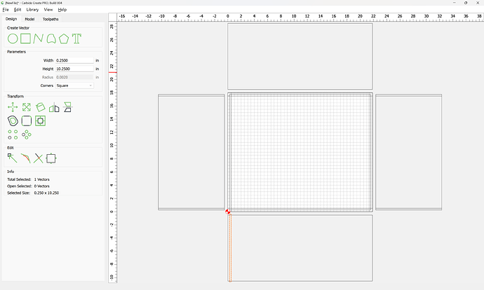
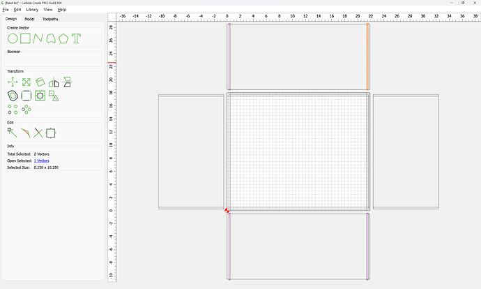
we do see one point of improvement — the groove unnecessarily shows at the sides, so we draw in 1/4" wide rectangles:
and Boolean Union them with the geometry for the front/back interior features:
OK
OK
If need be, adjust to ensure that the updated geometry is associated with the toolpaths.
Attached as a v8 file:
drawer_21_846x18x10_v8.c2d (84 KB)
Note that the above dimensions and toolpaths should be tested in a piece of scrap, and adjusted for fit, runout, &c. and may require calibration on a belt-drive machine.


