Hi there, I’m fairly new to Carbide Create but seem to have the basics figured out. I’m wanting to model a switch plate for a project that I’m working on, and know the basics like my stock dimensions and thickness and dimensions of the plate itself. I need a circle and rectangle cut out of the plate to allow for a charging port and power switch, and know the dimensions of those, but how can I specify how far down from the top of the plate the circle will be placed and how far down from that the rectangle will be placed? The charging port and switch are in a fixed location in the project and can’t be moved or separated, and I need to make sure that my cutouts line up with the port and switch. From the top of the plate the charging port is 20.5mm down, and is a 21m diameter circle. The switch is an additional 12.5mm down from the bottom edge of the circle and is 16.80mm x 29.25mm. Is there any way to specify these measurements?
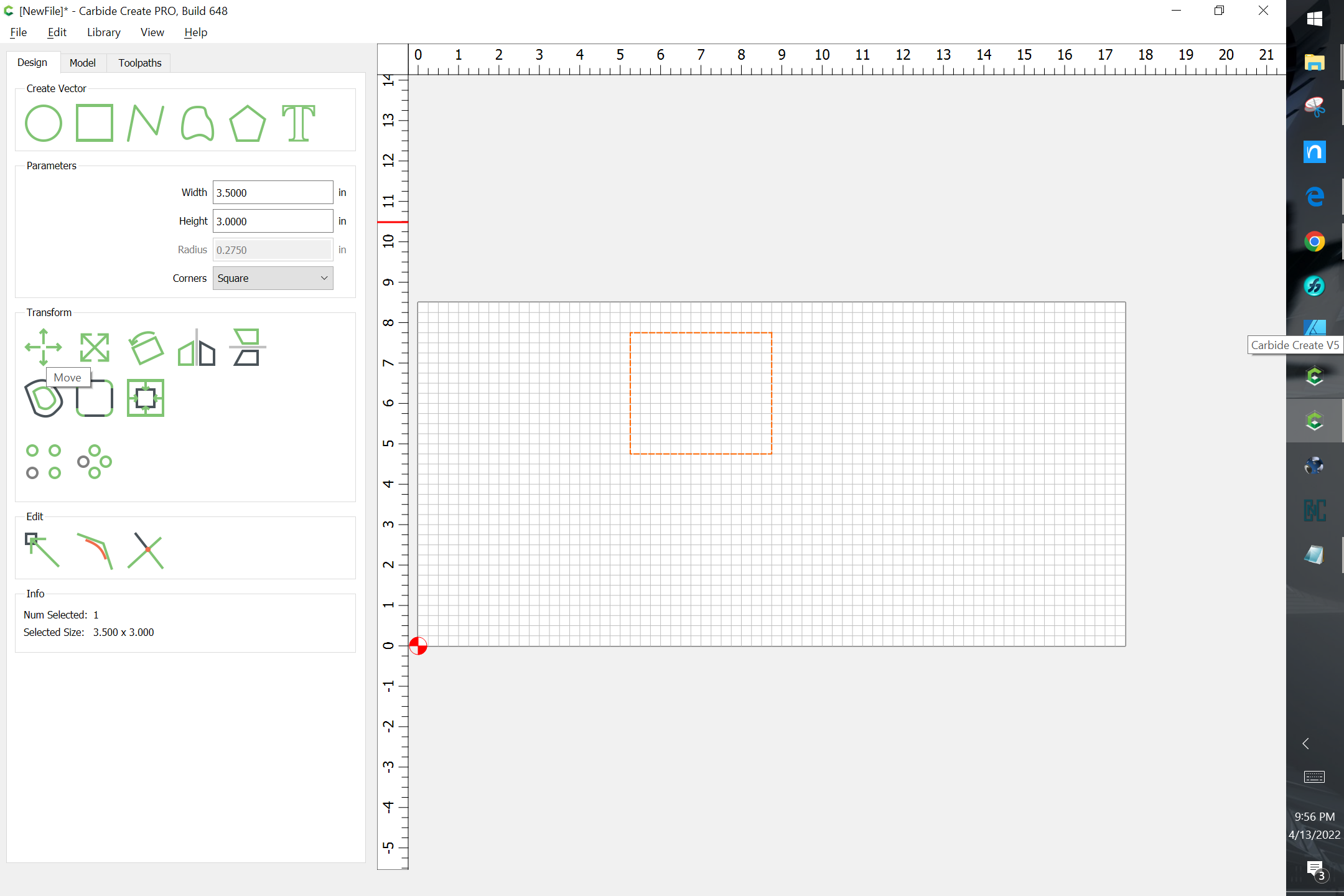
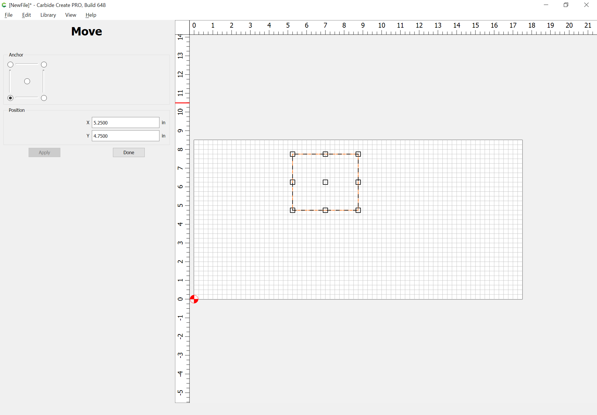
If you select an object, you can move it numerically:
Or, draw in rectangles to define the dimensions.
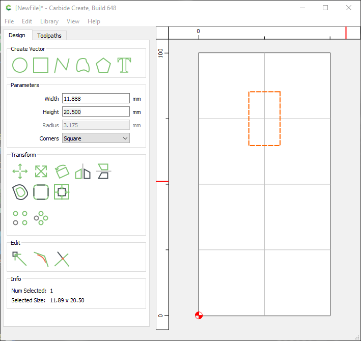
The easiest way is to draw extra geometry and use that for alignment. Once you have created a rectangle, you can click on it to change its properties and set its dimensions exactly.
test.c2d (14.9 KB)
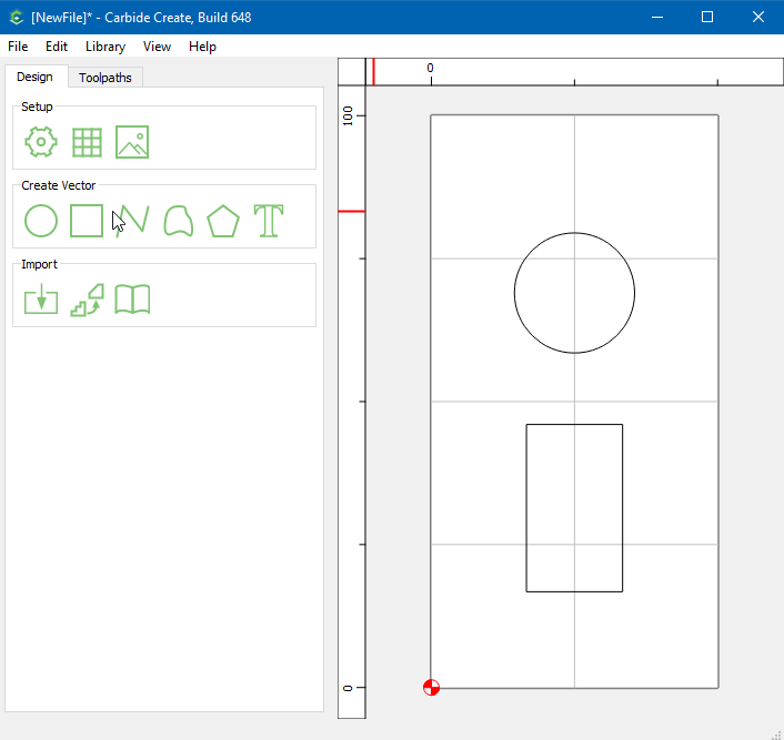
OK, so you have this:
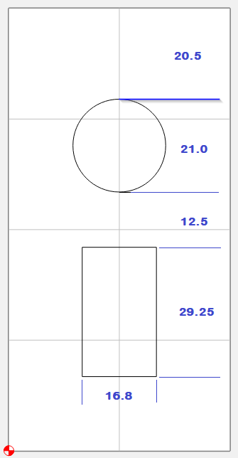
I didn’t know the plate dimensions, so went with a nice even 50 x 100. Set my grid to 25
Make a rectangle for the first dimension. Enter the height of 20.5
A cool thing about rectangles & circles is they have 4 nodes & 4 midpoints
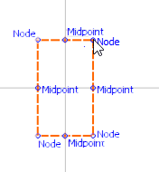
Grab the top midpoint, and drag the rectangle to the top-center of the grid

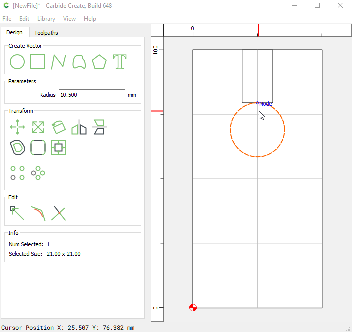
Now make your circle, adjust the radius to 10.5, and drag beneath the rectangle
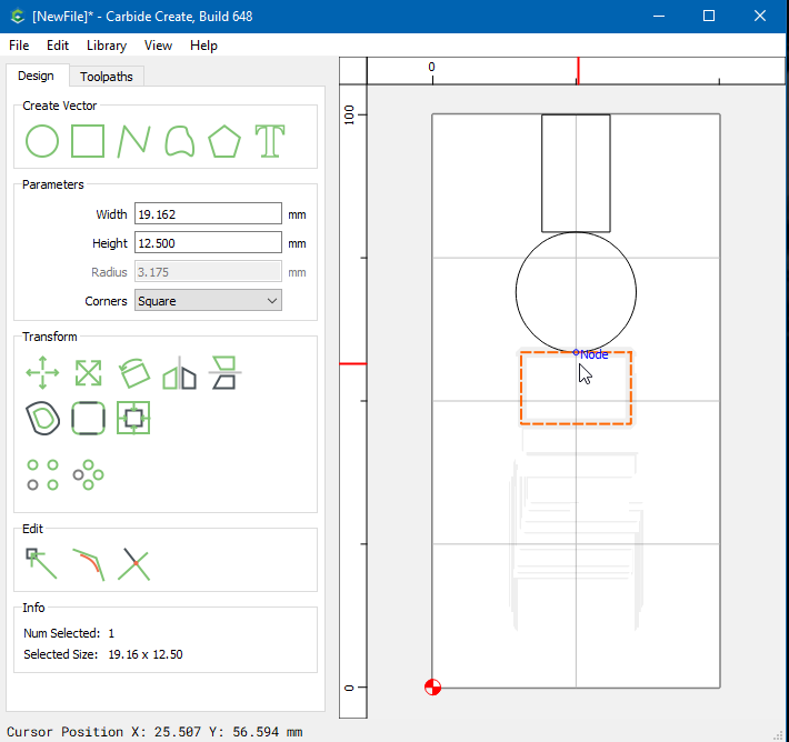
Make another rectangle, adjust the height to 12.5mm, and align with the circle
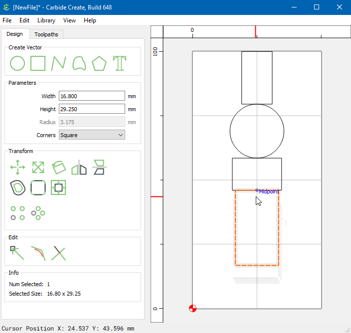
Make your last rectangle, adjust the size to 16.80mm x 29.25mm, and align with the last rectangle
Delete the 1st & 3rd rectangles
Viola! ![]()
@Tod1d
Great suggestion
What about this also?
-
Set your Stock Dimensions (X, Y & Z)
-
Base your grid-spacing off the distance youd like for all objects to be spaced apart from eachother. For example… if the plate has 3 items in it and youd like them all to be .25" apart from eachother then set your grid at that measurement.
-
With the “Snap-to-Grid” feature OFF, Draw in your Shapes. Then turn it back ON and space your shapes accordingly (allowing the grid to do the spacing for you)
-
Click on a shape to highlight it, then click the "Center-L&R button to instantly center it Left & Right on the stock. (Do this for each shape)
-
Once finished, Left-Click & hold it… while holding L-Click, draw a square around all the shapes to highlight them. Once highlighted, pin them all together.
-
Once pinned, use the Center to Stock button to get them all perfectly centered on the stock.
I think this is what you were asking. If so, I hope this helps.
If not, my apologies for misunderstanding.
- Yes. All his dimensions, except the 16.8 were divisible by 0.25, so that grid spacing would work.
- I don’t understand the “R-Click”. That pans the view. I think you mean Left-Click?? (unless you’re left handed.)
4,6. Left to right (horizontal) center would be useful with an odd width dimension. Top-Bottom (vertical) centering may or may not help. He had specific dimensions measured from the top. We don’t know the plate size, so no idea if it’s supposed to be vertically centered.
I tried to solve it using minimal math, with the information given. ![]()
OH SO SORRY…lol I meant L click…
I’ve corrected the error…lol
@MazdaSpeed1994
So what is the plate size and are you trying to center your work?
This topic was automatically closed after 30 days. New replies are no longer allowed.