I love designing objects in Fusion 360.
I hate manufacturing objects in Fusion 360.
I’ve been banging my head against the Manufacture tab in F360 for weeks now. I have what is a relatively simple object, a miter bar for a tablsaw, but I can’t figure out which toolpaths on my Shapeoko Pro will machine it accurately, where accurately is to within 0.1mm.
Help me, please.
Here’s the object:

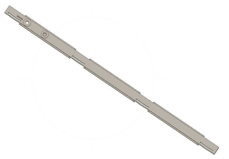
and the underside:
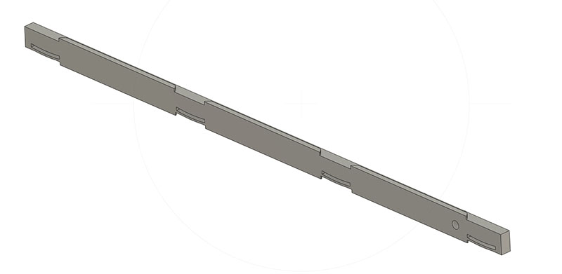
It’s about 594mm long, 26.5mm wide, and 10.3mm thick in the body.
The top width of the bar is sized to be slightly smaller than the miter slot. There are 4 “springs” milled into one side that protrude a tad and compress just slightly (like .45 mm) when slid into the slot - this stops the bar from wiggling even if the slot is worn and not a uniform width. It has two built-in washers with holes for attaching the gauge/fence unit. There are 3 “wings” in the lower portion of the bar that fit into the T-slot of the table to keep the bar from being lifted up while in use.
My main problem is that I can’t get the critical width of the bar to be accurate. I want it to be 19.9mm, have it specified as 19.65mm, but it comes out over 20mm, like 20.4mm, depending on what toolpaths I use.
Here’s my current toolpath setup:
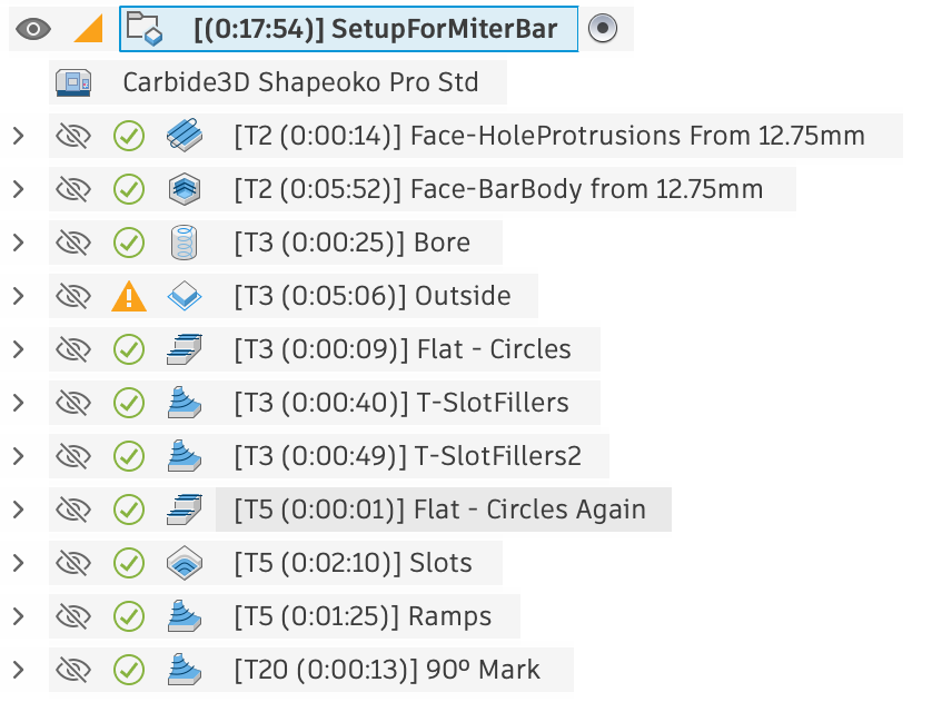
- Face the stock so that the thickness at the built-in washers and 90º mark is correct (about 11.8mm). This is OK.
- Face the stock so that the bar body thickness is 10.3mm. This is OK.
Switch to a ¼" end mill. - Bore the 2 holes. This is OK.
- 2D Contour the outside shape. Since this is 2D, not 3D, I key off the bottom. It cuts the wings well enough, but the curved spring portion is a bit wider than I’d expect. I’ve compensated for that with parameters, maybe I shouldn’t have.
- Flat the top built-in washers to get the areas missed by the larger diameter facing bit.
- 3D Contour the bar body width above the T-slot wings. This is where I’m having the most trouble. In my last attempt, the bar comes out too wide - consistent along the bar’s length. Here, I’m leaving 0.5mm of stock.
- 3D Contour the “Stock to Leave” portion. We’ll see if this helps, but I’d be surprised.
- Flat the top built-in washers again. Ugh, yet another issue, but this isn’t as bad to worry about just yet.
Switch to a ⅛" end mill - 2D Pocket the 5 curved slots. This works super-well, amazingly enough.
- 3D Contour the ends of the wings to have a ramp. This leaves a somewhat ragged ramp, but I’m not worried about that now.
Switch to a 60º Vee bit - 3D Contour a elogated pyramid to act as a line for the miter gauge. I’ve had some issues here getting the ¼" and ⅛" end mills to clear enough but not too much around this, but I’ll deal with that later.
I believe my machine is setup very well. I’ve bored holes spaced across an 18" square board and with pegs in the holes, they are very accurately located across the board. Due to the bar being longer than the X or Y of my standard size Pro, I have the bar at an angle. Maybe that’s causing some issue, but again, my machine appears to be accurately setup.
If you’re willing to look at my file, here it is:
MiterBar V12.f3d.zip (421.4 KB)
I’ve machined this in both phenolic and wood, btw. Unfortunately, I’m not even sure if the material I’m cutting affects the final results.
Maybe it’s my selection of toolpaths, it seems that I have a lot of them for a relatively simple shape. I couldn’t for instance, figure out a single 3D contour that would cut out the whole exterior shape, which is why I have the 2D contour for the bottom half and the 3D contour for the top half. That just seems wrong.
Help me, please!